
Image not available
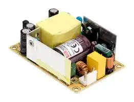
Illustrative purposes only

RPS-45-3.3
AC/DC Open Frame Power Supply (PSU), Medical, 1 Output, 26.4 W, 80V AC to 264V AC
⚠️ Reference pricing provided. In case of supply shortages, we will connect you with our trusted procurement partners to ensure your project's continuity.
- Manufacturer: MEAN WELL
- Product type: AC / DC Open Frame Power Supplies
- No. of Outputs:1 Output; Power Rating (Covection Cooling):26.4W; Power Rating (Forced Cooling):-; Input Voltage VAC:80V AC to 264V AC; Power Sup; Available until stocks are exhausted
- SVHC: No SVHC (12-Jan-2017)
- Product Range: RPS-45 Series
- No. of Outputs: 1 Output
- Output Power Max: 26.4W
- Input Voltage VAC: 80V AC to 264V AC
- Input Voltage AC Max: 264V
- Input Voltage AC Min: 80V
- Power Supply Output Type: Adjustable, Fixed
- Output Current - Output 1: 8A
- Output Current - Output 2: -
- Output Current - Output 3: -
- Output Current - Output 4: -
- Output Voltage - Output 1: 3.3VDC
- Output Voltage - Output 2: -
- Output Voltage - Output 3: -
- Output Voltage - Output 4: -
- Power Supply Applications: Medical
- Power Rating (Forced Cooling): -
- Power Rating (Convection Cooling): 26.4W
| Delivery and price | |
|---|---|
| Units per pack | 10 |
| Price | 8.4 € |
| Current stock | 10+ |
| Lead time | 30 days |
Datasheet

**RPS-45 series**

45W  Reliable Green Medical Power Supply

**User’s Manual**

## + + Os)Qs ~~=~~

## ■

## ■

Suitable for BF application with appropriate system consideration Cooling by free air convection

EMI class B for class Ⅱ configuration No load power consumption<0.1W Extremely low leakage current Protections: Short circuit / Overload / Over voltage Lifetime > 50 K hours

> ■ GTIN CODE MW Search: https://www.meanwell.com/serviceGTIN.aspx ~~a~~

## **Description**

RPS-45 is a 45W highly reliable green PCB type medical power supply with a high power density on the 3” by 2” footprint. It accepts 80~264VAC input and offers various output voltages between 3.3V and 48V. The working efficiency is up to 91% and the extremely low no load power consumption is down below 0.1W. RPS-45 is able to be used for ClassⅡ(no FG) system design. The extremely low leakage current is less than 100 μ A. In addition, it conforms to international medical regulations (2*MOPP) and EMC BS EN/EN55011, perfectly fitting all kinds of BF rated “patient contact” medical system equipment.

_File Name:R_ PS-45 _-SPEC 2022-09-20_

**RPS-45 series**

## 45W  Reliable Green Medical Power Supply

## **SPECIFICATION**

|**SPECIFICATION**|**SPECIFICATION**|**SPECIFICATION**||||
|---|---|---|---|---|---|
|**VOLTAGE TOLERANCE Note.4**<br>I/P-O/P: 4KVAC<br>**VOLTAGE ADJ.RANGE**<br>3.8~5V<br>5.7~6.8V<br>8.6~11.3V<br>13.8~16.2V<br>17.2~20.3V<br>28.4~32.4V<br>55.2~64.8V<br>**ORDER NO.**<br>**DC VOLTAGE**<br>**RATED CURRENT**<br>**CURRENT RANGE**<br>**RATED POWER**<br>**RIPPLE & NOISE (max.) Note.3**<br>**OUTPUT**<br>**VOLTAGE RANGE**<br>**Note.5**<br>**FREQUENCY RANGE**<br>**EFFICIENCY (Typ.)**<br>**AC CURRENT (Typ.)**<br>**INPUT**<br>**ENVIRONMENT**<br>**INRUSH CURRENT (Typ.)**<br>**LEAKAGE CURRENT(max.) Note.6**<br>**SAFETY STANDARDS**<br>**SAFETY &**<br>**EMC**<br>**(Note. 8)**<br>**WORKING TEMP.**<br>**WORKING HUMIDITY**<br>**STORAGE TEMP., HUMIDITY**<br>**TEMP. COEFFICIENT**<br>**VIBRATION**<br>**MTBF**<br>**DIMENSION   (L*W*H)**<br>**OTHERS**<br>**NOTE**<br>**PACKING**<br>**PROTECTION**<br>**RPS 45 3 3**<br>-<br>- .<br>3.3V<br>60mVp-p<br>**LINE REGULATION**<br>**LOAD REGULATION**<br>±0.5%<br>±2.0%<br>80 ~ 264VAC<br>47 ~ 63Hz<br>80 5%<br>.<br>1.2A / 115VAC          1A / 230VAC<br>**WITHSTAND VOLTAGE**<br>**ISOLATION RESISTANCE**<br>I/P-O/P:100M Ohms / 500VDC / 25<br>/ 70% RH<br>℃<br>-30 ~ +70<br>(Refer to "Derating Curve")<br>℃<br>20% ~ 90% RH non-condensing<br>-40 ~ +85<br>, 10 ~ 95% RHnon-condensing<br>℃<br>10 ~ 500Hz, 2G 10min./1cycle, period for 60min. each along X, Y, Z axes<br>76.2*50.8*24mm or  3" * 2" *0.945" inch<br>0.11Kg; 120pcs/14.2Kg/0.94CUFT<br>**OVERLOAD**<br>**OVER VOLTAGE**<br>115 ~ 150%  rated output power<br>Protection type : Hiccup mode, recovers automatically after fault condition is removed<br>8A<br>0 ~ 8 8A<br>.<br>26.4W<br>Protection type :Shut down o/p voltage, re-power on to recover<br>**SETUP, RISE TIME**<br>**HOLD UP TIME (Typ.)**<br>500ms, 30ms / 230VAC          500ms, 30ms / 115VAC  at full load<br>30ms / 230VAC          16ms / 115VAC  at full load<br>±0.03%  /<br>(0 ~ 50<br>)<br>℃<br>℃<br>**ISOLATION LEVEL**<br>Primary-Secondary: 2xMOPP<br>1. All parameters NOT specially mentioned are measured at 230VAC input, rated load and 25<br>of ambient temperature.<br>℃<br>2. 33% Duty cycle maximum within every 30 seconds. Average output power should not exceed the rated power.<br>3. Ripple & noise are measured at 20MHz of bandwidth by using a 12" twisted pair-wire terminated with a 0.1  f & 47  f parallel capacitor.<br>4. Tolerance : includes set up tolerance, line regulation and load regulation.<br>5. Derating may be needed under low input voltages. Please check the derating curve for more details.<br>6. Touch current was measured from primary input to DC output.<br>����������������������������������<br>�����������������������������<br>���������������������������������������������������������������<br>℃<br>℃<br>7.<br>8. The power supply is considered a component which will be installed into a final equipment. "All the EMC tests are been executed by mounting<br>the unit on a 360mm*360mm metal plate with 1mm of thickness." The final equipment must be re-confirmed that it still meets EMC directives.<br>For guidance on how to perform these EMC tests, please refer to “EMI testing of component power supplies.”<br>(as available on http://www.meanwell.com)<br>https://www.meanwell.com/serviceDisclaimer.aspx<br>※��������������������������<br>������������������������������������<br>:<br>**PEAK LOAD(10sec.)**<br>**Note.2** 29W<br>3.1~3.6V<br>±2.0%<br>Touch current< 100 A/264VAC<br>**RPS 45**<br>-<br>-**5**<br>5V<br>60mVp-p<br>±0.5%<br>±2.0%<br>83%<br>8A<br>0 ~ 8 8A<br>.<br>40W<br>44W<br>4 7 5 5<br>. ~ . V<br>±2.0%<br>**RPS 45**<br>-<br>- .**7 5**<br>7.5V<br>80mVp-p<br>±0.5%<br>±2.0%<br>85%<br>0 ~ 5.95A<br>40.5W<br>44.6W<br>7.12~8.3V<br>±2.0%<br>**RPS 45**<br>-<br>-**12**<br>12V<br>100mVp-p<br>±0.5%<br>±2.0%<br>88%<br>5.4A<br>0 ~ 4.18A<br>11.4~13.2V<br>±2.0%<br>**RPS 45**<br>-<br>-**15**<br>15V<br>100mVp-p<br>±0.5%<br>±1.0%<br>89%<br>3.8A<br>0 ~ 3 3A<br>.<br>13.5~16.5V<br>±1.0%<br>**RPS 45**<br>-<br>-**24**<br>24V<br>120mVp-p<br>±0.5%<br>±1.0%<br>90%<br>1.9A<br>0 ~ 2.1A<br>22.8~27.6V<br>±1.0%<br>**RPS 45**<br>-<br>-**48**<br>48V<br>120mVp-p<br>±0.5%<br>±1.0%<br>91%<br>0.94A<br>0 ~ 1.03A<br>45.6~52.8V<br>±1.0%<br>3A<br>45.6W<br>50.2W<br>45W<br>49.5W<br>45.6W<br>50.2W<br>45.1W<br>49.4W<br>СOLD STAR  30A/115VAC    60A/230VAC<br>**OPERATING ALTITUDE Note.7** 4000 meters<br>**Parameter**<br>**Parameter**<br>ESD<br>**Standard**<br>**Standard**<br>BS EN/EN55011 (CISPR11)<br>BS EN/EN55011 (CISPR11)<br>BS EN/EN61000-3-2<br>BS EN/EN61000-3-3<br>BS EN/EN61000-4-2<br>BS EN/EN61000-4-3<br>BS EN/EN61000-4-4<br>BS EN/EN61000-4-5<br>BS EN/EN61000-4-6<br>BS EN/EN61000-4-8<br>BS EN/EN61000-4-11<br>**Test Level / Note**<br>**Test Level / Note**<br>Class B<br>Class B<br>Class A<br>-----<br>**EMC IMMUNITY**<br>**EMC EMISSION**<br>BS EN/EN55035, BS EN/EN60601-1-2<br>100% dip 1 periods, 30% dip 25 periods,<br>100% interruptions 250 periods<br>IEC60601-1, TUV BS EN/EN60601-1,<br>,UL ANSI / AAMI  ES60601-1 (3.1 version),<br>EAC TP TC 004<br>CAN/CSA-C22.2 No. 60601-1:14 - Edition 3  approved;Design refer to BS EN/EN60335 1-<br>μ<br>μ<br>μ<br>RF field susceptibility<br>EFT bursts<br>Surge susceptibility<br>Conducted susceptibility<br>Magnetic field immunity<br>Voltage dip, interruption<br>Conducted emission<br>Radiated emission<br>Harmonic current<br>Voltage flicker<br>Level 4, 15KV air ; Level 4, 8KV contact<br>Level 4, 2KV/Line-Line<br>Level 4, 30A/m<br>Level 3, 10V<br>Level 3, 2KV<br>Level 3, 10V/m( 80MHz~2.7GHz )<br>Table 9, 9~28V/m( 385MHz~5.78GHz )<br>3334.3K hrs min.<br>Telcordia SR-332 (Bellcore) ; 726.2K hrs min.      MIL-HDBK-217F (25<br>)<br>℃||||||
||**VOLTAGE TOLERANCE Note.4**<br>I/P-O/P: 4KVAC<br>**VOLTAGE ADJ.RANGE**<br>3.8~5V<br>5.7~6.8V<br>8.6~11.3V<br>13.8~16.2V<br>17.2~20.3V<br>28.4~32.4V<br>55.2~64.8V<br>**ORDER NO.**<br>**DC VOLTAGE**<br>**RATED CURRENT**<br>**CURRENT RANGE**<br>**RATED POWER**<br>**RIPPLE & NOISE (max.) Note.3**<br>**OUTPUT**<br>**VOLTAGE RANGE**<br>**Note.5**<br>**FREQUENCY RANGE**<br>**EFFICIENCY (Typ.)**<br>**AC CURRENT (Typ.)**<br>**INPUT**<br>**ENVIRONMENT**<br>**INRUSH CURRENT (Typ.)**<br>**LEAKAGE CURRENT(max.) Note.6**<br>**SAFETY STANDARDS**<br>**SAFETY &**<br>**EMC**<br>**(Note. 8)**<br>**WORKING TEMP.**<br>**WORKING HUMIDITY**<br>**STORAGE TEMP., HUMIDITY**<br>**TEMP. COEFFICIENT**<br>**VIBRATION**<br>**MTBF**<br>**DIMENSION   (L*W*H)**<br>**OTHERS**<br>**PACKING**<br>**PROTECTION**<br>**RPS 45 3 3**<br>-<br>- .<br>3.3V<br>60mVp-p<br>**LINE REGULATION**<br>**LOAD REGULATION**<br>±0.5%<br>±2.0%<br>80 ~ 264VAC<br>47 ~ 63Hz<br>80 5%<br>.<br>1.2A / 115VAC          1A / 230VAC<br>**WITHSTAND VOLTAGE**<br>**ISOLATION RESISTANCE**<br>I/P-O/P:100M Ohms / 500VDC / 25<br>/ 70% RH<br>℃<br>-30 ~ +70<br>(Refer to "Derating Curve")<br>℃<br>20% ~ 90% RH non-condensing<br>-40 ~ +85<br>, 10 ~ 95% RHnon-condensing<br>℃<br>10 ~ 500Hz, 2G 10min./1cycle, period for 60min. each along X, Y, Z axes<br>76.2*50.8*24mm or  3" * 2" *0.945" inch<br>0.11Kg; 120pcs/14.2Kg/0.94CUFT<br>**OVERLOAD**<br>**OVER VOLTAGE**<br>115 ~ 150%  rated output power<br>Protection type : Hiccup mode, recovers automatically after fault condition is removed<br>8A<br>0 ~ 8 8A<br>.<br>26.4W<br>Protection type :Shut down o/p voltage, re-power on to recover<br>**SETUP, RISE TIME**<br>**HOLD UP TIME (Typ.)**<br>500ms, 30ms / 230VAC          500ms, 30ms / 115VAC  at full load<br>30ms / 230VAC          16ms / 115VAC  at full load<br>±0.03%  /<br>(0 ~ 50<br>)<br>℃<br>℃<br>**ISOLATION LEVEL**<br>Primary-Secondary: 2xMOPP<br>1. All parameters NOT specially mentioned are measured at 230VAC input, rated load and 25<br>of ambient temperature.<br>℃<br>2. 33% Duty cycle maximum within every 30 seconds. Average output power should not exceed the rated power.<br>3. Ripple & noise are measured at 20MHz of bandwidth by using a 12" twisted pair-wire terminated with a 0.1  f & 47  f parallel capacitor.<br>4. Tolerance : includes set up tolerance, line regulation and load regulation.<br>**PEAK LOAD(10sec.)**<br>**Note.2** 29W<br>3.1~3.6V<br>±2.0%<br>Touch current< 100 A/264VAC<br>**RPS 45**<br>-<br>-**5**<br>5V<br>60mVp-p<br>±0.5%<br>±2.0%<br>83%<br>8A<br>0 ~ 8 8A<br>.<br>40W<br>44W<br>4 7 5 5<br>. ~ . V<br>±2.0%<br>**RPS 45**<br>-<br>- .**7 5**<br>7.5V<br>80mVp-p<br>±0.5%<br>±2.0%<br>85%<br>0 ~ 5.95A<br>40.5W<br>44.6W<br>7.12~8.3V<br>±2.0%<br>**RPS 45**<br>-<br>-**12**<br>12V<br>100mVp-p<br>±0.5%<br>±2.0%<br>88%<br>5.4A<br>0 ~ 4.18A<br>11.4~13.2V<br>±2.0%<br>**RPS 45**<br>-<br>-**15**<br>15V<br>100mVp-p<br>±0.5%<br>±1.0%<br>89%<br>3.8A<br>0 ~ 3 3A<br>.<br>13.5~16.5V<br>±1.0%<br>**RPS 45**<br>-<br>-**24**<br>24V<br>120mVp-p<br>±0.5%<br>±1.0%<br>90%<br>1.9A<br>0 ~ 2.1A<br>22.8~27.6V<br>±1.0%<br>**RPS 45**<br>-<br>-**48**<br>48V<br>120mVp-p<br>±0.5%<br>±1.0%<br>91%<br>0.94A<br>0 ~ 1.03A<br>45.6~52.8V<br>±1.0%<br>3A<br>45.6W<br>50.2W<br>45W<br>49.5W<br>45.6W<br>50.2W<br>45.1W<br>49.4W<br>СOLD STAR  30A/115VAC    60A/230VAC<br>**OPERATING ALTITUDE Note.7** 4000 meters<br>**Parameter**<br>**Parameter**<br>ESD<br>**Standard**<br>**Standard**<br>BS EN/EN55011 (CISPR11)<br>BS EN/EN55011 (CISPR11)<br>BS EN/EN61000-3-2<br>BS EN/EN61000-3-3<br>BS EN/EN61000-4-2<br>BS EN/EN61000-4-3<br>BS EN/EN61000-4-4<br>BS EN/EN61000-4-5<br>BS EN/EN61000-4-6<br>BS EN/EN61000-4-8<br>BS EN/EN61000-4-11<br>**Test Level / Note**<br>**Test Level / Note**<br>Class B<br>Class B<br>Class A<br>-----<br>**EMC IMMUNITY**<br>**EMC EMISSION**<br>BS EN/EN55035, BS EN/EN60601-1-2<br>100% dip 1 periods, 30% dip 25 periods,<br>100% interruptions 250 periods<br>IEC60601-1, TUV BS EN/EN60601-1,<br>,UL ANSI / AAMI  ES60601-1 (3.1 version),<br>EAC TP TC 004<br>CAN/CSA-C22.2 No. 60601-1:14 - Edition 3  approved;Design refer to BS EN/EN60335 1-<br>μ<br>μ<br>μ<br>RF field susceptibility<br>EFT bursts<br>Surge susceptibility<br>Conducted susceptibility<br>Magnetic field immunity<br>Voltage dip, interruption<br>Conducted emission<br>Radiated emission<br>Harmonic current<br>Voltage flicker<br>Level 4, 15KV air ; Level 4, 8KV contact<br>Level 4, 2KV/Line-Line<br>Level 4, 30A/m<br>Level 3, 10V<br>Level 3, 2KV<br>Level 3, 10V/m( 80MHz~2.7GHz )<br>Table 9, 9~28V/m( 385MHz~5.78GHz )<br>3334.3K hrs min.<br>Telcordia SR-332 (Bellcore) ; 726.2K hrs min.      MIL-HDBK-217F (25<br>)<br>℃||**RPS 45 3 3**<br>-<br>- .<br>**RPS 45**<br>-<br>-**5**<br>**RPS 45**<br>-<br>- .**7 5**<br>**RPS 45**<br>-<br>-**12**<br>**RPS 45**<br>-<br>-**15**<br>**RPS 45**<br>-<br>-**24**<br>**RPS 45**<br>-<br>-**48**|||
|||**DC VOLTAGE**|3.3V<br>5V<br>7.5V<br>12V<br>15V<br>24V<br>48V|||
|||**RATED CURRENT**|8A<br>8A<br>5.4A<br>3.8A<br>1.9A<br>0.94A<br>3A|||
|||**CURRENT RANGE**|0 ~ 8 8A<br>.<br>0 ~ 8 8A<br>.<br>0 ~ 5.95A<br>0 ~ 4.18A<br>0 ~ 3 3A<br>.<br>0 ~ 2.1A<br>0 ~ 1.03A|||
|||**RATED POWER**|26.4W<br>40W<br>40.5W<br>45.6W<br>45W<br>45.6W<br>45.1W|||
|||**PEAK LOAD(10sec.)**<br>**Note.2**|29W<br>44W<br>44.6W<br>50.2W<br>49.5W<br>50.2W<br>49.4W|||
|||**RIPPLE & NOISE (max.) Note.3**|60mVp-p<br>60mVp-p<br>80mVp-p<br>100mVp-p<br>100mVp-p<br>120mVp-p<br>120mVp-p|||
|||**VOLTAGE ADJ.RANGE**|3.1~3.6V<br>4 7 5 5<br>. ~ . V<br>7.12~8.3V<br>11.4~13.2V<br>13.5~16.5V<br>22.8~27.6V<br>45.6~52.8V|||
|||**VOLTAGE TOLERANCE Note.4**|±2.0%<br>±2.0%<br>±2.0%<br>±2.0%<br>±1.0%<br>±1.0%<br>±1.0%|||
|||**LINE REGULATION**|±0.5%<br>±0.5%<br>±0.5%<br>±0.5%<br>±0.5%<br>±0.5%<br>±0.5%|||
|||**LOAD REGULATION**|±2.0%<br>±2.0%<br>±2.0%<br>±2.0%<br>±1.0%<br>±1.0%<br>±1.0%|||
|||**SETUP, RISE TIME**|500ms, 30ms / 230VAC          500ms, 30ms / 115VAC  at full load|||
|||**HOLD UP TIME (Typ.)**|30ms / 230VAC          16ms / 115VAC  at full load|||
|||**VOLTAGE RANGE**<br>**Note.5**|80 ~ 264VAC|||
|||**FREQUENCY RANGE**|47 ~ 63Hz|||
|||**EFFICIENCY (Typ.)**|80 5%<br>.<br>83%<br>85%<br>88%<br>89%<br>90%<br>91%|||
|||**AC CURRENT (Typ.)**|1.2A / 115VAC          1A / 230VAC|||
|||**INRUSH CURRENT (Typ.)**|СOLD STAR  30A/115VAC    60A/230VAC|||
|||**LEAKAGE CURRENT(max.) Note.6**|Touch current< 100 A/264VAC<br>μ|||
|||**OVERLOAD**|115 ~ 150%  rated output power<br>Protection type : Hiccup mode, recovers automatically after fault condition is removed|||
|||**OVER VOLTAGE**|3.8~5V<br>5.7~6.8V<br>8.6~11.3V<br>13.8~16.2V<br>17.2~20.3V<br>28.4~32.4V<br>55.2~64.8V<br>Protection type :Shut down o/p voltage, re-power on to recover|||
|||**WORKING TEMP.**|-30 ~ +70<br>(Refer to "Derating Curve")<br>℃|||
|||**WORKING HUMIDITY**|20% ~ 90% RH non-condensing|||
|||**STORAGE TEMP., HUMIDITY**|-40 ~ +85<br>, 10 ~ 95% RHnon-condensing<br>℃|||
|||**TEMP. COEFFICIENT**|±0.03%  /<br>(0 ~ 50<br>)<br>℃<br>℃|||
|||**VIBRATION**|10 ~ 500Hz, 2G 10min./1cycle, period for 60min. each along X, Y, Z axes<br> <br>|||
|||**SAFETY STANDARDS**<br>**OPERATING ALTITUDE Note.7**|4000 meters<br>IEC60601-1, TUV BS EN/EN60601-1,<br>,UL ANSI / AAMI  ES60601-1 (3.1 version),<br>EAC TP TC 004<br>CAN/CSA-C22.2 No. 60601-1:14 - Edition 3  approved;Design refer to BS EN/EN60335 1-|||
|||**ISOLATION LEVEL**|Primary-Secondary: 2xMOPP|||
|||**WITHSTAND VOLTAGE**|I/P-O/P: 4KVAC|||
|||**ISOLATION RESISTANCE**|I/P-O/P:100M Ohms / 500VDC / 25<br>/ 70% RH<br>℃|||
|||**MTBF**<br>**EMC IMMUNITY**<br>**EMC EMISSION**|**Parameter**|**Standard**|**Test Level / Note**|
||||Conducted emission|BS EN/EN55011 (CISPR11)|Class B|
||||Radiated emission|BS EN/EN55011 (CISPR11)|Class B|
||||Harmonic current|BS EN/EN61000-3-2|Class A|
||||Voltage flicker|BS EN/EN61000-3-3|-----|
||||BS EN/EN55035, BS EN/EN60601-1-2|||
||||**Parameter**|**Standard**|**Test Level / Note**|
||||ESD|BS EN/EN61000-4-2|Level 4, 15KV air ; Level 4, 8KV contact|
||||RF field susceptibility|BS EN/EN61000-4-3|Level 3, 10V/m( 80MHz~2.7GHz )<br>Table 9, 9~28V/m( 385MHz~5.78GHz )|
||||EFT bursts|BS EN/EN61000-4-4|Level 3, 2KV|
||||Surge susceptibility|BS EN/EN61000-4-5|Level 4, 2KV/Line-Line|
||||Conducted susceptibility|BS EN/EN61000-4-6|Level 3, 10V|
||||Magnetic field immunity|BS EN/EN61000-4-8|Level 4, 30A/m|
||||Voltage dip, interruption|BS EN/EN61000-4-11|100% dip 1 periods, 30% dip 25 periods,<br>100% interruptions 250 periods|
||||3334.3K hrs min.<br>Telcordia SR-332 (Bellcore) ; 726.2K hrs min.      MIL-HDBK-217F (25<br>)<br>℃|||
|||**DIMENSION   (L*W*H)**|76.2*50.8*24mm or  3" * 2" *0.945" inch|||
|||**PACKING**<br>0.11Kg; 120pcs/14.2Kg/0.94CUFT<br>1. All parameters NOT specially mentioned are measured at 230VAC input, rated load and 25<br>of ambient temperature.<br>℃<br>2. 33% Duty cycle maximum within every 30 seconds. Average output power should not exceed the rated power.<br>3. Ripple & noise are measured at 20MHz of bandwidth by using a 12" twisted pair-wire terminated with a 0.1  f & 47  f parallel capacitor.<br>4. Tolerance : includes set up tolerance, line regulation and load regulation.<br>μ<br>μ||||
|||5. Derating may be needed under low input voltages. Please check the derating curve for more details.<br>6. Touch current was measured from primary input to DC output.<br>����������������������������������<br>�����������������������������<br>���������������������������������������������������������������<br>℃<br>℃<br>7.<br>8. The power supply is considered a component which will be installed into a final equipment. "All the EMC tests are been executed by mounting<br>the unit on a 360mm*360mm metal plate with 1mm of thickness." The final equipment must be re-confirmed that it still meets EMC directives.<br>For guidance on how to perform these EMC tests, please refer to “EMI testing of component power supplies.”<br>(as available on http://www.meanwell.com)<br>https://www.meanwell.com/serviceDisclaimer.aspx<br>※��������������������������<br>������������������������������������<br>:||||


5. Derating may be needed under low input voltages. Please check the derating curve for more details.

**NOTE** 6. Touch current was measured from primary input to DC output. 7. ���������������������������������������℃�����������������������������������℃������������������������������������������������������������������������ 8. The power supply is considered a component which will be installed into a final equipment. "All the EMC tests are been executed by mounting the unit on a 360mm*360mm metal plate with 1mm of thickness." The final equipment must be re-confirmed that it still meets EMC directives. For guidance on how to perform these EMC tests, please refer to “EMI testing of component power supplies.” (as available on http://www.meanwell.com)

※�����������������������������:����������������������������������������� https://www.meanwell.com/serviceDisclaimer.aspx

_File Name:R_ PS-45 _-SPEC 2022-09-20_

**RPS-45 series**

45W  Reliable Green Medical Power Supply

**==> picture [487 x 628] intentionally omitted <==**

**----- Start of picture text -----**<br>
Block Diagram<br>fosc : 65KHz<br>EMI  FILTER RECTIFIERS RECTIFIERS<br>POWER +V<br>I/P & & &<br>SWITCHING -V<br>RECTIFIER FILTER FILTER<br>DETECTION<br>CIRCUIT<br>O.L.P. CONTROL<br>O.V.P.<br>Derating Curve<br>100<br>80<br>60<br>50<br>40<br>20<br>-30 0 10 20 30 40 50 60 70 (HORIZONTAL)<br>AMBIENT TEMPERATURE ( ℃ )<br>Static Characteristics<br>100<br>90<br>80<br>70<br>60<br>50<br>40<br>80 100 115 120 140 160 180 200 220 240 264<br>INPUT VOLTAGE (V) 60Hz<br>LOAD (%)<br>LOAD (%)<br>**----- End of picture text -----**<br>


_File Name:R_ PS-45 _-SPEC 2022-09-20_

**RPS-45 series**

45W  Reliable Green Medical Power Supply

**==> picture [347 x 351] intentionally omitted <==**

**----- Start of picture text -----**<br>
Mechanical Specification<br>Top View<br>76.2<br>3.175<br>69.85<br>FS1 AC FUSE HS100<br>T2A/250V<br>3<br>2<br>CN2<br>1<br>1<br>CN1<br>2<br>3<br>4<br>LED<br>HS1 SVR1<br>4-ψ3.2<br>Side View<br>3 max.<br>24<br>50.8 44.45<br>3.175<br>**----- End of picture text -----**<br>


Case No.    Unit:mm

AC Input Connector (CN1) : JST B3P-VH or equivalent

|Pin No.|Assignment|Mating Housing|Terminal|
|---|---|---|---|
|1|AC/N|JST VHR<br>or equivalent|JST SVH-21T-P1.1<br>or equivalent|
|2|No Pin|||
|3|AC/L|||


DC Output Connector (CN2) : JST B4P-VH or equivalent

|Pin No.|Assignment|Mating Housing|Terminal|
|---|---|---|---|
|1|+V<br>+V<br>-V<br>-V|JST VHR<br>or equivalent|JST SVH-21T-P1.1<br>or equivalent|
|2||||
|3||||
|4||||


## **Installation Manual**

Please refer to : http://www.meanwell.com/manual.html

_File Name:R_ PS-45 _-SPEC 2022-09-20_
Updated at June 10, 2026
About Novapart
Novapart is a B2B electronic component broker specialising in stock shortages and cost reduction. We source hard-to-find parts and identify compliant alternatives across a catalogue of 410,000+ components from 500+ manufacturers.
Learn more →Stock Shortage Specialist
When a component is unavailable, discontinued or has an unacceptable lead time, we tap into our network of vetted European and Asian distributors to source what you need — without compromising on quality or traceability.
Request a quote →Compliant Alternatives
We identify pin-to-pin, electrically equivalent substitutes that meet the same certifications (RoHS, AEC-Q100, REACH) as your original specification — validated against datasheets, not just part numbers. Often at a lower cost.
BOM Analysis service →