
Image not available
Illustrative purposes only

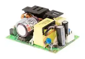
RPS-120S-27
AC/DC Open Frame Power Supply (PSU), Medical, 1 Output, 119.9 W, 80V AC to 264V AC
⚠️ Reference pricing provided. In case of supply shortages, we will connect you with our trusted procurement partners to ensure your project's continuity.
- Manufacturer: MEAN WELL
- Product type: AC / DC Open Frame Power Supplies
- SVHC: No SVHC (25-Jun-2025)
- Product Range: RPS-120S Series
- No. of Outputs: 1 Output
- Input Voltage VAC: 80V AC to 264V AC
- Power Supply Output Type: Adjustable, Fixed
- Output Current - Output 1: 4.44A
- Output Current - Output 2: -
- Output Current - Output 3: -
- Output Current - Output 4: -
- Output Voltage - Output 1: 27VDC
- Output Voltage - Output 2: -
- Output Voltage - Output 3: -
- Output Voltage - Output 4: -
- Power Supply Applications: Medical
- Power Rating (Forced Cooling): -
- Power Rating (Convection Cooling): 119.9W
| Delivery and price | |
|---|---|
| Units per pack | 100 |
| Price | 31.91 € |
| Current stock | 10+ |
| Lead time | 30 days |
Datasheet

**RPS - 120S series**

120W  3"×2" Reliable Green Medical Power Supply

## ■

## + + ■

* Suitable for BF application with appropriate system consideration * EMI for both Class Ⅰ & Class Ⅱ configuration ℃

## ■

Ⅰ (with FG) & Class Ⅱ

**==> picture [13 x 11] intentionally omitted <==**

**----- Start of picture text -----**<br>
■<br>**----- End of picture text -----**<br>


_File Name:RPS-120S-SPEC   2019-09-02_

## 120W  3"×2" Reliable Green Medical Power Supply

## **RPS-120S series**

## **SPECIFICATION**

## **MODEL**

|**MODEL**<br>**DC VOLTAGE**<br>**CURRENT**<br>**Peak(10 sec.)**<br>**Convection**<br>**Convection**<br>**RATED**<br>**POWER**<br>**OUTPUT**<br>**LINE REGULATION**<br>**VOLTAGE ADJ. RANGE**<br>**LOAD REGULATION**<br>**SETUP, RISE TIME**<br>**HOLD UP TIME (Typ.)**<br>**VOLTAGE RANGE**<br>**Note.4**<br>**FREQUENCY RANGE**<br>**EFFICIENCY (Typ.)**<br>**INPUT**<br>**INRUSH CURRENT (Typ.)**<br>**ISOLATION RESISTANCE**<br>**WORKING HUMIDITY**<br>**WORKING TEMP.**<br>**OVER TEMPERATURE**<br>**STORAGE TEMP.**<br>**TEMP. COEFFICIENT**<br>**VIBRATION**<br>**MTBF**<br>**DIMENSION  (L*W*H)**<br>**OTHERS**<br>**NOTE**<br>**PACKING**<br>**OVERLOAD**<br>**OVER VOLTAGE**<br>**AC CURRENT (Typ.)**<br>600ms, 30ms/230VAC        600ms, 30ms/115VAC at full load<br>15ms/230VAC          15ms/115VAC at full load<br>80 ~ 264VAC          113 ~ 370VDC<br>47 ~ 63Hz<br>92%<br>91%<br>93%<br>16.5 ~ 19.5V<br>94%<br>26.4 ~ 31.2V<br>93.5%<br>29.7 ~ 35V<br>52.8 ~ 62.4V<br>2.3A/115VAC          1.1A/230VAC<br>COLD START<br>30A/115VAC          60A/230VAC<br>130~160% rated output power<br>13.2 ~ 15.6V<br>Protection type : Hiccup mode, recovers automatically after fault condition is removed<br>20 ~ 90% RH non-condensing<br>-30 ~ +85<br>(Refer to "Derating Curve")<br>℃<br>-40 ~ +85℃<br>±<br>℃<br>℃<br>0.03%/<br>(0 ~ 50<br>)<br>10 ~ 500Hz, 2G 10min./1cycle, 60min. each along X, Y, Z axes<br>468Khrs min.      MIL-HDBK-217F (25<br>)<br>℃<br>76.2*50.8*28mmor 3" * 2" *1.1" inch<br>±1.0%<br>±0.5%<br>±1.0%<br>±0.5%<br>±1.0%<br>±0.5%<br>±0.5%<br>±1.0%<br>±1.0%<br>±0.5%<br>±2.0%<br>±2.0%<br>±1.0%<br>±1.0%<br>±1.0%<br>100mVp-p<br>11.4~12.6V<br>14.3~15.8V<br>22.8~25.2V<br>25.6 ~ 28.4V<br>45.6 ~50.4V<br>120mVp-p<br>150mVp-p<br>150mVp-p<br>200mVp-p<br>15V<br>24V<br>27V<br>48V<br>11.8A<br>9.5A<br>9.5A<br>7.6A<br>6.25A<br>5A<br>5.55A<br>4.44A<br>3.125A<br>2.5A<br>141.6W<br>114W<br>114W<br>142.5W<br>120W<br>150W<br>119.9W<br>149.8W<br>120W<br>150W<br>**RPS-120S-12**<br>**RPS-120S-15**<br>**RPS-120S-24**<br>**RPS-120S-27**<br>**RPS-120S-48**<br>**SAFETY STANDARDS**<br>**RIPPLE & NOISE (max.) Note.2**<br>**VOLTAGE TOLERANCE Note.3**<br>6.<br>℃<br>℃<br>**ENVIRONMENT**<br>**SAFETY &**<br>**EMC**<br>**(Note 7)**<br>**PROTECTION**<br>Primary-Secondary: 2xMOPP, Primary-Earth:1xMOPP, Secondary-Earth:1xMOPP<br>IEC60601-1, TUV EN60601-1,<br>, UL ANSI / AAMI ES60601-1 (3.1 version),<br>EAC TP TC 004<br>CAN/CSA-C22.2 No. 60601-1:14 - Edition 3  approved;Design refer to EN60335 1 (By request)<br>-<br>12V<br>**LEAKAGE CURRENT(max.) Note.5** Earth leakage current < 150 A/264VAC , touch current < 80 A/264VAC<br>**WITHSTAND VOLTAGE**<br>**ISOLATION RESISTANCE**<br>I/P-O/P:4KVAC     I/P-FG:2KVAC     O/P-FG:1.5KVAC<br>I/P-O/P, I/P-FG, O/P-FG: 100M Ohms / 500VDC / 25<br>/ 70% RH<br>℃<br>Protection type : Shut down o/p voltage, re-power on to recover<br>Protection type :S<br>o/p<br>hut down<br>voltage, recovers automatically after temperature goes down<br>**Parameter**<br>**Parameter**<br>ESD<br>**Standard**<br>**Standard**<br>EN55011 (CISPR11)<br>EN55011 (CISPR11)<br>EN61000-3-2<br>EN61000-3-3<br>EN61000-4-2<br>EN61000-4-3<br>EN61000-4-4<br>EN61000-4-5<br>EN61000-4-6<br>EN61000-4-8<br>EN61000-4-11<br>**Test Level / Note**<br>**Test Level / Note**<br>Class B<br>Class A<br>-----<br>**EMC IMMUNITY**<br>**EMC EMISSION**<br>EN60601-1-2<br>95% dip 1 periods, 30% dip 25 periods,<br>95% interruptions 250 periods<br>**OPERATING ALTITUDE Note.6** 4000 meters<br>μ<br>RF field susceptibility<br>EFT bursts<br>Surge susceptibility<br>Conducted susceptibility<br>Magnetic field immunity<br>Voltage dip, interruption<br>Conducted emission<br>Radiated emission<br>Harmonic current<br>Voltage flicker<br>Level 4, 15KV air ; Level 4, 8KV contact<br>Level 4, 30A/m<br>Level 3, 10V<br>Level 3, 2KV<br>Level 4, 4KV/Line-FG; 2KV/Line-Line<br>Level 3, 10V/m( 80MHz~2.7GHz )<br>Table 9, 9~28V/m( 385MHz~5.78GHz )<br>**Peak(10 sec.)**<br>μ<br>**POWER FACTOR**<br>PF>0.94/230VAC       PF>0.98/115VAC at full load<br>0.13Kg; 100pcs/14Kg/1.13CUFT<br>Class<br>: Class B<br>Class<br>Ⅰ<br>Ⅱ<br>, Class<br>:<br>A<br>1. All parameters NOT specially mentioned are measured at 230VAC input, rated load and 25 of ambient temperature.<br>2. Ripple & noise are measured at20MHz of bandwidth by using a 12" twisted pair-wire terminated witha0O.<br>&4 _ parallel capacitor.<br>3. Tolerance: includes set up tolerance, line regulation and load regulation.<br>4. Derating may be needed under low input voltages. Please check the derating curve for more details.<br>5. Touch current was measured from primary input to DC output.<br>The ambient temperature derating of 3.5<br>/1000m with fanless models and of<br>5<br>+ /1000m with fan models for operating altitude higher than 2000m(6500ft)<br>7. The power supply is considered a component which will be installed into a final equipment. All the EMC tests are been executed by<br>mounting the unit on<br>a 360mm*360mm metal plate with 1mm of thickness. The final equipment must be re-confirmed that it still meets<br>EMC directives. For guidance on how to perform these EMC tests, please refer to “EMI testing of component power supplies.”<br>(as available on http:/Avww.meanwell.com)|**MODEL**<br>**DC VOLTAGE**<br>**CURRENT**<br>**Peak(10 sec.)**<br>**Convection**<br>**Convection**<br>**RATED**<br>**POWER**<br>**OUTPUT**<br>**LINE REGULATION**<br>**VOLTAGE ADJ. RANGE**<br>**LOAD REGULATION**<br>**SETUP, RISE TIME**<br>**HOLD UP TIME (Typ.)**<br>**VOLTAGE RANGE**<br>**Note.4**<br>**FREQUENCY RANGE**<br>**EFFICIENCY (Typ.)**<br>**INPUT**<br>**INRUSH CURRENT (Typ.)**<br>**ISOLATION RESISTANCE**<br>**WORKING HUMIDITY**<br>**WORKING TEMP.**<br>**OVER TEMPERATURE**<br>**STORAGE TEMP.**<br>**TEMP. COEFFICIENT**<br>**VIBRATION**<br>**MTBF**<br>**DIMENSION  (L*W*H)**<br>**OTHERS**<br>**NOTE**<br>**PACKING**<br>**OVERLOAD**<br>**OVER VOLTAGE**<br>**AC CURRENT (Typ.)**<br>600ms, 30ms/230VAC        600ms, 30ms/115VAC at full load<br>15ms/230VAC          15ms/115VAC at full load<br>80 ~ 264VAC          113 ~ 370VDC<br>47 ~ 63Hz<br>92%<br>91%<br>93%<br>16.5 ~ 19.5V<br>94%<br>26.4 ~ 31.2V<br>93.5%<br>29.7 ~ 35V<br>52.8 ~ 62.4V<br>2.3A/115VAC          1.1A/230VAC<br>COLD START<br>30A/115VAC          60A/230VAC<br>130~160% rated output power<br>13.2 ~ 15.6V<br>Protection type : Hiccup mode, recovers automatically after fault condition is removed<br>20 ~ 90% RH non-condensing<br>-30 ~ +85<br>(Refer to "Derating Curve")<br>℃<br>-40 ~ +85℃<br>±<br>℃<br>℃<br>0.03%/<br>(0 ~ 50<br>)<br>10 ~ 500Hz, 2G 10min./1cycle, 60min. each along X, Y, Z axes<br>468Khrs min.      MIL-HDBK-217F (25<br>)<br>℃<br>76.2*50.8*28mmor 3" * 2" *1.1" inch<br>±1.0%<br>±0.5%<br>±1.0%<br>±0.5%<br>±1.0%<br>±0.5%<br>±0.5%<br>±1.0%<br>±1.0%<br>±0.5%<br>±2.0%<br>±2.0%<br>±1.0%<br>±1.0%<br>±1.0%<br>100mVp-p<br>11.4~12.6V<br>14.3~15.8V<br>22.8~25.2V<br>25.6 ~ 28.4V<br>45.6 ~50.4V<br>120mVp-p<br>150mVp-p<br>150mVp-p<br>200mVp-p<br>15V<br>24V<br>27V<br>48V<br>11.8A<br>9.5A<br>9.5A<br>7.6A<br>6.25A<br>5A<br>5.55A<br>4.44A<br>3.125A<br>2.5A<br>141.6W<br>114W<br>114W<br>142.5W<br>120W<br>150W<br>119.9W<br>149.8W<br>120W<br>150W<br>**RPS-120S-12**<br>**RPS-120S-15**<br>**RPS-120S-24**<br>**RPS-120S-27**<br>**RPS-120S-48**<br>**SAFETY STANDARDS**<br>**RIPPLE & NOISE (max.) Note.2**<br>**VOLTAGE TOLERANCE Note.3**<br>6.<br>℃<br>℃<br>**ENVIRONMENT**<br>**SAFETY &**<br>**EMC**<br>**(Note 7)**<br>**PROTECTION**<br>Primary-Secondary: 2xMOPP, Primary-Earth:1xMOPP, Secondary-Earth:1xMOPP<br>IEC60601-1, TUV EN60601-1,<br>, UL ANSI / AAMI ES60601-1 (3.1 version),<br>EAC TP TC 004<br>CAN/CSA-C22.2 No. 60601-1:14 - Edition 3  approved;Design refer to EN60335 1 (By request)<br>-<br>12V<br>**LEAKAGE CURRENT(max.) Note.5** Earth leakage current < 150 A/264VAC , touch current < 80 A/264VAC<br>**WITHSTAND VOLTAGE**<br>**ISOLATION RESISTANCE**<br>I/P-O/P:4KVAC     I/P-FG:2KVAC     O/P-FG:1.5KVAC<br>I/P-O/P, I/P-FG, O/P-FG: 100M Ohms / 500VDC / 25<br>/ 70% RH<br>℃<br>Protection type : Shut down o/p voltage, re-power on to recover<br>Protection type :S<br>o/p<br>hut down<br>voltage, recovers automatically after temperature goes down<br>**Parameter**<br>**Parameter**<br>ESD<br>**Standard**<br>**Standard**<br>EN55011 (CISPR11)<br>EN55011 (CISPR11)<br>EN61000-3-2<br>EN61000-3-3<br>EN61000-4-2<br>EN61000-4-3<br>EN61000-4-4<br>EN61000-4-5<br>EN61000-4-6<br>EN61000-4-8<br>EN61000-4-11<br>**Test Level / Note**<br>**Test Level / Note**<br>Class B<br>Class A<br>-----<br>**EMC IMMUNITY**<br>**EMC EMISSION**<br>EN60601-1-2<br>95% dip 1 periods, 30% dip 25 periods,<br>95% interruptions 250 periods<br>**OPERATING ALTITUDE Note.6** 4000 meters<br>μ<br>RF field susceptibility<br>EFT bursts<br>Surge susceptibility<br>Conducted susceptibility<br>Magnetic field immunity<br>Voltage dip, interruption<br>Conducted emission<br>Radiated emission<br>Harmonic current<br>Voltage flicker<br>Level 4, 15KV air ; Level 4, 8KV contact<br>Level 4, 30A/m<br>Level 3, 10V<br>Level 3, 2KV<br>Level 4, 4KV/Line-FG; 2KV/Line-Line<br>Level 3, 10V/m( 80MHz~2.7GHz )<br>Table 9, 9~28V/m( 385MHz~5.78GHz )<br>**Peak(10 sec.)**<br>μ<br>**POWER FACTOR**<br>PF>0.94/230VAC       PF>0.98/115VAC at full load<br>0.13Kg; 100pcs/14Kg/1.13CUFT<br>Class<br>: Class B<br>Class<br>Ⅰ<br>Ⅱ<br>, Class<br>:<br>A<br>1. All parameters NOT specially mentioned are measured at 230VAC input, rated load and 25 of ambient temperature.<br>2. Ripple & noise are measured at20MHz of bandwidth by using a 12" twisted pair-wire terminated witha0O.<br>&4 _ parallel capacitor.<br>3. Tolerance: includes set up tolerance, line regulation and load regulation.<br>4. Derating may be needed under low input voltages. Please check the derating curve for more details.<br>5. Touch current was measured from primary input to DC output.<br>The ambient temperature derating of 3.5<br>/1000m with fanless models and of<br>5<br>+ /1000m with fan models for operating altitude higher than 2000m(6500ft)<br>7. The power supply is considered a component which will be installed into a final equipment. All the EMC tests are been executed by<br>mounting the unit on<br>a 360mm*360mm metal plate with 1mm of thickness. The final equipment must be re-confirmed that it still meets<br>EMC directives. For guidance on how to perform these EMC tests, please refer to “EMI testing of component power supplies.”<br>(as available on http:/Avww.meanwell.com)|**MODEL**<br>**DC VOLTAGE**<br>**CURRENT**<br>**Peak(10 sec.)**<br>**Convection**<br>**Convection**<br>**RATED**<br>**POWER**<br>**OUTPUT**<br>**LINE REGULATION**<br>**VOLTAGE ADJ. RANGE**<br>**LOAD REGULATION**<br>**SETUP, RISE TIME**<br>**HOLD UP TIME (Typ.)**<br>**VOLTAGE RANGE**<br>**Note.4**<br>**FREQUENCY RANGE**<br>**EFFICIENCY (Typ.)**<br>**INPUT**<br>**INRUSH CURRENT (Typ.)**<br>**ISOLATION RESISTANCE**<br>**WORKING HUMIDITY**<br>**WORKING TEMP.**<br>**OVER TEMPERATURE**<br>**STORAGE TEMP.**<br>**TEMP. COEFFICIENT**<br>**VIBRATION**<br>**MTBF**<br>**DIMENSION  (L*W*H)**<br>**OTHERS**<br>**NOTE**<br>**PACKING**<br>**OVERLOAD**<br>**OVER VOLTAGE**<br>**AC CURRENT (Typ.)**<br>600ms, 30ms/230VAC        600ms, 30ms/115VAC at full load<br>15ms/230VAC          15ms/115VAC at full load<br>80 ~ 264VAC          113 ~ 370VDC<br>47 ~ 63Hz<br>92%<br>91%<br>93%<br>16.5 ~ 19.5V<br>94%<br>26.4 ~ 31.2V<br>93.5%<br>29.7 ~ 35V<br>52.8 ~ 62.4V<br>2.3A/115VAC          1.1A/230VAC<br>COLD START<br>30A/115VAC          60A/230VAC<br>130~160% rated output power<br>13.2 ~ 15.6V<br>Protection type : Hiccup mode, recovers automatically after fault condition is removed<br>20 ~ 90% RH non-condensing<br>-30 ~ +85<br>(Refer to "Derating Curve")<br>℃<br>-40 ~ +85℃<br>±<br>℃<br>℃<br>0.03%/<br>(0 ~ 50<br>)<br>10 ~ 500Hz, 2G 10min./1cycle, 60min. each along X, Y, Z axes<br>468Khrs min.      MIL-HDBK-217F (25<br>)<br>℃<br>76.2*50.8*28mmor 3" * 2" *1.1" inch<br>±1.0%<br>±0.5%<br>±1.0%<br>±0.5%<br>±1.0%<br>±0.5%<br>±0.5%<br>±1.0%<br>±1.0%<br>±0.5%<br>±2.0%<br>±2.0%<br>±1.0%<br>±1.0%<br>±1.0%<br>100mVp-p<br>11.4~12.6V<br>14.3~15.8V<br>22.8~25.2V<br>25.6 ~ 28.4V<br>45.6 ~50.4V<br>120mVp-p<br>150mVp-p<br>150mVp-p<br>200mVp-p<br>15V<br>24V<br>27V<br>48V<br>11.8A<br>9.5A<br>9.5A<br>7.6A<br>6.25A<br>5A<br>5.55A<br>4.44A<br>3.125A<br>2.5A<br>141.6W<br>114W<br>114W<br>142.5W<br>120W<br>150W<br>119.9W<br>149.8W<br>120W<br>150W<br>**RPS-120S-12**<br>**RPS-120S-15**<br>**RPS-120S-24**<br>**RPS-120S-27**<br>**RPS-120S-48**<br>**SAFETY STANDARDS**<br>**RIPPLE & NOISE (max.) Note.2**<br>**VOLTAGE TOLERANCE Note.3**<br>6.<br>℃<br>℃<br>**ENVIRONMENT**<br>**SAFETY &**<br>**EMC**<br>**(Note 7)**<br>**PROTECTION**<br>Primary-Secondary: 2xMOPP, Primary-Earth:1xMOPP, Secondary-Earth:1xMOPP<br>IEC60601-1, TUV EN60601-1,<br>, UL ANSI / AAMI ES60601-1 (3.1 version),<br>EAC TP TC 004<br>CAN/CSA-C22.2 No. 60601-1:14 - Edition 3  approved;Design refer to EN60335 1 (By request)<br>-<br>12V<br>**LEAKAGE CURRENT(max.) Note.5** Earth leakage current < 150 A/264VAC , touch current < 80 A/264VAC<br>**WITHSTAND VOLTAGE**<br>**ISOLATION RESISTANCE**<br>I/P-O/P:4KVAC     I/P-FG:2KVAC     O/P-FG:1.5KVAC<br>I/P-O/P, I/P-FG, O/P-FG: 100M Ohms / 500VDC / 25<br>/ 70% RH<br>℃<br>Protection type : Shut down o/p voltage, re-power on to recover<br>Protection type :S<br>o/p<br>hut down<br>voltage, recovers automatically after temperature goes down<br>**Parameter**<br>**Parameter**<br>ESD<br>**Standard**<br>**Standard**<br>EN55011 (CISPR11)<br>EN55011 (CISPR11)<br>EN61000-3-2<br>EN61000-3-3<br>EN61000-4-2<br>EN61000-4-3<br>EN61000-4-4<br>EN61000-4-5<br>EN61000-4-6<br>EN61000-4-8<br>EN61000-4-11<br>**Test Level / Note**<br>**Test Level / Note**<br>Class B<br>Class A<br>-----<br>**EMC IMMUNITY**<br>**EMC EMISSION**<br>EN60601-1-2<br>95% dip 1 periods, 30% dip 25 periods,<br>95% interruptions 250 periods<br>**OPERATING ALTITUDE Note.6** 4000 meters<br>μ<br>RF field susceptibility<br>EFT bursts<br>Surge susceptibility<br>Conducted susceptibility<br>Magnetic field immunity<br>Voltage dip, interruption<br>Conducted emission<br>Radiated emission<br>Harmonic current<br>Voltage flicker<br>Level 4, 15KV air ; Level 4, 8KV contact<br>Level 4, 30A/m<br>Level 3, 10V<br>Level 3, 2KV<br>Level 4, 4KV/Line-FG; 2KV/Line-Line<br>Level 3, 10V/m( 80MHz~2.7GHz )<br>Table 9, 9~28V/m( 385MHz~5.78GHz )<br>**Peak(10 sec.)**<br>μ<br>**POWER FACTOR**<br>PF>0.94/230VAC       PF>0.98/115VAC at full load<br>0.13Kg; 100pcs/14Kg/1.13CUFT<br>Class<br>: Class B<br>Class<br>Ⅰ<br>Ⅱ<br>, Class<br>:<br>A<br>1. All parameters NOT specially mentioned are measured at 230VAC input, rated load and 25 of ambient temperature.<br>2. Ripple & noise are measured at20MHz of bandwidth by using a 12" twisted pair-wire terminated witha0O.<br>&4 _ parallel capacitor.<br>3. Tolerance: includes set up tolerance, line regulation and load regulation.<br>4. Derating may be needed under low input voltages. Please check the derating curve for more details.<br>5. Touch current was measured from primary input to DC output.<br>The ambient temperature derating of 3.5<br>/1000m with fanless models and of<br>5<br>+ /1000m with fan models for operating altitude higher than 2000m(6500ft)<br>7. The power supply is considered a component which will be installed into a final equipment. All the EMC tests are been executed by<br>mounting the unit on<br>a 360mm*360mm metal plate with 1mm of thickness. The final equipment must be re-confirmed that it still meets<br>EMC directives. For guidance on how to perform these EMC tests, please refer to “EMI testing of component power supplies.”<br>(as available on http:/Avww.meanwell.com)|**RPS-120S-12**|**RPS-120S-15**|**RPS-120S-15**|**RPS-120S-24**|**RPS-120S-27**|**RPS-120S-27**|**RPS-120S-48**|
|---|---|---|---|---|---|---|---|---|---|
||**DC VOLTAGE**||12V|15V||24V|27V||48V|
||**CURRENT**<br>**Peak(10 sec.)**<br>**Convection**<br>**Convection**<br>**RATED**<br>**POWER**<br>**RIPPLE & NOISE (max.) Note.2**<br>**Peak(10 sec.)**|**Peak(10 sec.)**|11.8A|9.5A||6.25A|5.55A||3.125A|
|||**Convection**|9.5A|7.6A||5A|4.44A||2.5A|
|||**Peak(10 sec.)**|141.6W|142.5W||150W|149.8W||150W|
|||**Convection**|114W|114W||120W|119.9W||120W|
||||100mVp-p|120mVp-p||150mVp-p|150mVp-p||200mVp-p|
||**VOLTAGE ADJ. RANGE**||11.4~12.6V|14.3~15.8V||22.8~25.2V|25.6 ~ 28.4V||45.6 ~50.4V|
||**VOLTAGE TOLERANCE Note.3**||±2.0%|±2.0%||±1.0%|±1.0%||±1.0%|
||**LINE REGULATION**||±0.5%|±0.5%||±0.5%|±0.5%||±0.5%|
||**LOAD REGULATION**||±1.0%|±1.0%||±1.0%|±1.0%||±1.0%|
||**SETUP, RISE TIME**||600ms, 30ms/230VAC        600ms, 30ms/115VAC at full load|||||||
||**HOLD UP TIME (Typ.)**||15ms/230VAC          15ms/115VAC at full load|||||||
||**VOLTAGE RANGE**<br>**Note.4**||80 ~ 264VAC          113 ~ 370VDC|||||||
||**FREQUENCY RANGE**||47 ~ 63Hz|||||||
||**POWER FACTOR**||PF>0.94/230VAC       PF>0.98/115VAC at full load|||||||
||**EFFICIENCY (Typ.)**||91%|92%||93%|94%||93.5%|
||**AC CURRENT (Typ.)**||2.3A/115VAC          1.1A/230VAC|||||||
||**INRUSH CURRENT (Typ.)**||COLD START<br>30A/115VAC          60A/230VAC|||||||
||**LEAKAGE CURRENT(max.) Note.5**||Earth leakage current < 150 A/264VAC , touch current < 80 A/264VAC<br>μ<br>μ|||||||
||**OVERLOAD**||130~160% rated output power<br>Protection type : Hiccup mode, recovers automatically after fault condition is removed|||||||
||**OVER VOLTAGE**||16.5 ~ 19.5V<br>26.4 ~ 31.2V<br>29.7 ~ 35V<br>52.8 ~ 62.4V<br>13.2 ~ 15.6V<br>Protection type : Shut down o/p voltage, re-power on to recover|||||||
||**OVER TEMPERATURE**||Protection type :S<br>o/p<br>hut down<br>voltage, recovers automatically after temperature goes down|||||||
||**WORKING TEMP.**||-30 ~ +85<br>(Refer to "Derating Curve")<br>℃|||||||
||**WORKING HUMIDITY**||20 ~ 90% RH non-condensing|||||||
||**STORAGE TEMP.**||-40 ~ +85℃|||||||
||**TEMP. COEFFICIENT**||±<br>℃<br>℃<br>0.03%/<br>(0 ~ 50<br>)|||||||
||**VIBRATION**||10 ~ 500Hz, 2G 10min./1cycle, 60min. each along X, Y, Z axes|||||||
||**OPERATING ALTITUDE Note.6**||4000 meters|||||||
||**SAFETY STANDARDS**||IEC60601-1, TUV EN60601-1,<br>, UL ANSI / AAMI ES60601-1 (3.1 version),<br>EAC TP TC 004<br>CAN/CSA-C22.2 No. 60601-1:14 - Edition 3  approved;Design refer to EN60335 1 (By request)<br>-|||||||
||**ISOLATION RESISTANCE**||Primary-Secondary: 2xMOPP, Primary-Earth:1xMOPP, Secondary-Earth:1xMOPP|||||||
||**WITHSTAND VOLTAGE**||I/P-O/P:4KVAC     I/P-FG:2KVAC     O/P-FG:1.5KVAC|||||||
||**MTBF**<br>**ISOLATION RESISTANCE**<br>**EMC IMMUNITY**<br>**EMC EMISSION**||I/P-O/P, I/P-FG, O/P-FG: 100M Ohms / 500VDC / 25<br>/ 70% RH<br>℃<br>**Parameter**<br>**Standard**<br>**Test Level / Note**|||||||
||||Conducted emission||EN55011 (CISPR11)|||Class B||
||||Radiated emission||EN55011 (CISPR11)|||Class<br>: Class B<br>Class<br>Ⅰ<br>Ⅱ<br>, Class<br>:<br>A||
||||Harmonic current||EN61000-3-2|||Class A||
||||Voltage flicker||EN61000-3-3|||-----||
||||EN60601-1-2|||||||
||||**Parameter**||**Standard**|||**Test Level / Note**||
||||ESD||EN61000-4-2|||Level 4, 15KV air ; Level 4, 8KV contact||
||||RF field susceptibility||EN61000-4-3|||Level 3, 10V/m( 80MHz~2.7GHz )<br>Table 9, 9~28V/m( 385MHz~5.78GHz )||
||||EFT bursts||EN61000-4-4|||Level 3, 2KV<br>Table 9, 9~28V/m( 385MHz~5.78GHz )||
||||Surge susceptibility||EN61000-4-5|||Level 4, 4KV/Line-FG; 2KV/Line-Line||
||||Conducted susceptibility||EN61000-4-6|||Level 3, 10V||
||||Magnetic field immunity||EN61000-4-8|||Level 4, 30A/m||
||||Voltage dip, interruption||EN61000-4-11|||95% dip 1 periods, 30% dip 25 periods,<br>95% interruptions 250 periods||
||||468Khrs min.      MIL-HDBK-217F (25<br>)<br>℃|||||||
||**DIMENSION  (L*W*H)**||76.2*50.8*28mmor 3" * 2" *1.1" inch|||||||
||**PACKING**<br>6.<br>℃<br>℃<br>0.13Kg; 100pcs/14Kg/1.13CUFT<br>1. All parameters NOT specially mentioned are measured at 230VAC input, rated load and 25 of ambient temperature.<br>2. Ripple & noise are measured at20MHz of bandwidth by using a 12" twisted pair-wire terminated witha0O.<br>&4 _ parallel capacitor.<br>3. Tolerance: includes set up tolerance, line regulation and load regulation.<br>4. Derating may be needed under low input voltages. Please check the derating curve for more details.<br>5. Touch current was measured from primary input to DC output.<br>The ambient temperature derating of 3.5<br>/1000m with fanless models and of<br>5<br>+ /1000m with fan models for operating altitude higher than 2000m(6500ft)<br>7. The power supply is considered a component which will be installed into a final equipment. All the EMC tests are been executed by<br>mounting the unit on<br>a 360mm*360mm metal plate with 1mm of thickness. The final equipment must be re-confirmed that it still meets<br>EMC directives. For guidance on how to perform these EMC tests, please refer to “EMI testing of component power supplies.”<br>(as available on http:/Avww.meanwell.com)|||||||||


_File Name:RPS-120S-SPEC   2019-09-02_

**RPS-120S series**

## 120W  3"×2" Reliable Green Medical Power Supply

**==> picture [78 x 12] intentionally omitted <==**

**----- Start of picture text -----**<br>
Block Diagram<br>**----- End of picture text -----**<br>


**==> picture [471 x 596] intentionally omitted <==**

**----- Start of picture text -----**<br>
fosc : 85KHz<br>EMI RECTIFIERS POWER RECTIFIERS +V<br>I/P FILTER PFC& SWITCHING FILTER& -V<br>FG<br>DETECTION<br>CIRCUIT<br>O.T.P. O.L.P. CONTROL<br>O.V.P.<br>Derating Curve<br>Convection<br>100<br>80<br>70<br>60<br>50<br>30<br>-30 0 10 20 30 40 50 70 85 (HORIZONTAL)<br>AMBIENT TEMPERATURE ( ℃ )<br>Output Derating VS Input Voltage<br>(for 24V/27V/48V)<br>120W<br>114W<br>(for 12V/15V)<br>100W<br>80W<br>80 90 110 120 130 140 160 180 200 220 240 264<br>INPUT VOLTAGE (VAC) 60Hz<br>LOAD (%)<br>LOAD (W)<br>**----- End of picture text -----**<br>


_File Name:RPS-120S-SPEC   2019-09-02_

## 120W  3"×2" Reliable Green Medical Power Supply

## **RPS-120S series**

## **Mechanical Specification**

**==> picture [351 x 303] intentionally omitted <==**

**----- Start of picture text -----**<br>
Unit:mm<br>SVR1<br>C100<br>HS1<br>1<br>2<br>3<br>FS1 T1 CN100<br>C5 4<br>3<br>2<br>1<br>C105<br>C1<br>FS2 T3.15A C119<br>/250V<br>3.175 69.9<br>76.2<br>4-<br>ψ<br>3.3<br>50.8<br>28<br>T3.15A/250V<br>CN1<br>3.175<br>44.45<br>3 max.<br>**----- End of picture text -----**<br>


|AC Input Connector (CN1) : JST B3P-VH or equivalent<br>Pin No.<br>1<br>2<br>3<br>Assignment<br>AC/L<br>No Pin<br>AC/N<br>Mating Housing<br>JST VHR<br>JST SVH-21T-P1.1<br>or equivalent<br>or equivalent<br>Terminal|AC Input Connector (CN1) : JST B3P-VH or equivalent<br>Pin No.<br>1<br>2<br>3<br>Assignment<br>AC/L<br>No Pin<br>AC/N<br>Mating Housing<br>JST VHR<br>JST SVH-21T-P1.1<br>or equivalent<br>or equivalent<br>Terminal|AC Input Connector (CN1) : JST B3P-VH or equivalent<br>Pin No.<br>1<br>2<br>3<br>Assignment<br>AC/L<br>No Pin<br>AC/N<br>Mating Housing<br>JST VHR<br>JST SVH-21T-P1.1<br>or equivalent<br>or equivalent<br>Terminal|AC Input Connector (CN1) : JST B3P-VH or equivalent<br>Pin No.<br>1<br>2<br>3<br>Assignment<br>AC/L<br>No Pin<br>AC/N<br>Mating Housing<br>JST VHR<br>JST SVH-21T-P1.1<br>or equivalent<br>or equivalent<br>Terminal|DC Output Connector (CN2) : JST B4P-VH or equivalent<br>Pin No.<br>1,2<br>3,4<br>Assignment<br>-V<br>+V<br>Mating Housing<br>JST VHR<br>or equivalent<br>Terminal<br>JST SVH-21T-P1.1<br>or equivalent|
|---|---|---|---|---|
|Pin No.|Assignment|Mating Housing|Terminal||
|1|AC/L|JST VHR<br>or equivalent|JST SVH-21T-P1.1<br>or equivalent||
|2|No Pin||||
|3|AC/N||||


1.HS1 must have safety isolation distance with system case.

※Note :

1.RPS-120S  model delivers EMI Class B for both conducted emission and radiated emission for the power supply, when configured into Class Ⅰ(with FG) system. 2.RPS-120S  model delivers EMI Class B conducted emission and Class A radiated emission with King Core K5B RC (12*15*7) in output cable for the power supply when configured into Class Ⅱ (no FG) system.

## **Installation Manual**

Please refer to : http://www.meanwell.com/manual.html

_File Name:RPS-120S-SPEC   2019-09-02_
Updated at June 10, 2026
About Novapart
Novapart is a B2B electronic component broker specialising in stock shortages and cost reduction. We source hard-to-find parts and identify compliant alternatives across a catalogue of 410,000+ components from 500+ manufacturers.
Learn more →Stock Shortage Specialist
When a component is unavailable, discontinued or has an unacceptable lead time, we tap into our network of vetted European and Asian distributors to source what you need — without compromising on quality or traceability.
Request a quote →Compliant Alternatives
We identify pin-to-pin, electrically equivalent substitutes that meet the same certifications (RoHS, AEC-Q100, REACH) as your original specification — validated against datasheets, not just part numbers. Often at a lower cost.
BOM Analysis service →