
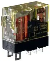


RJ22S-CL-A120
RELAY, DPDT, 250VAC, 30VDC, 8A
- Manufacturer: IDEC
- Product type: Power Relays
- Coil Type: Non Latching
- Coil Voltage: 120VAC
- Product Range: RJ Series
- Relay Mounting: Socket
- Coil Resistance: 6.4kohm
- Contact Current: 8A
- Relay Terminals: Quick Connect
- Contact Material: Silver Nickel
- Contact Voltage VAC: 250VAC
- Contact Voltage VDC: 30VDC
- Contact Configuration: DPDT
| Delivery and price | |
|---|---|
| Units per pack | 10 |
| Price | 11.61 € |
| Current stock | 10+ |
| Lead time | 7 days |
## RJ Series

## Slim Power Relays (Bifurcated Contacts)

**==> picture [397 x 430] intentionally omitted <==**

**----- Start of picture text -----**<br>
• RJ22S Plug-in Terminal • RJ22V PC Board Terminal<br>SS<br>When mounted in a socket<br>High contact reliability<br>with bifurcated contacts CO) 2-pole SJ sockets<br>Standard Screw Terminals Finger-safe Screw PC Board Terminals<br>Terminals (IP20)<br>15.5mm 15.5mm<br>71mm 71mm<br>55.7mm 55.7mm<br>**----- End of picture text -----**<br>


(110620)

RJ Series Slim Power Relay Plug-in Terminal (bifurcated contacts)

## **High contact reliability with bifurcated contacts (minimum applicable load: 1V DC, 100µA)**

- The smallest width for 2-pole/bifurcated contacts relay (based on IDEC research as of April 2011)

- Non-polarized green LED indicator available (except for simple type)

- IDEC’s unique light-guide structure enables an RJ relay to be identified by the illuminating LED.

- Diode, reverse polarity diode, and RC circuits are available.

-

-

- Peak inverse voltage is 1000V.

- UL recognized, CSA certified, VDE approved, EN compliant.

**Applicable Standards** Standards Mark File No. or Organization ~~a ee ee~~ UL508 UL Recognized File No. E55996 CSA CSA C22.2 No.14 File No. LR35144 VDE No. 40015055 EN61810-1 EU Low Voltage Directive ~~| ee~~

**==> picture [221 x 105] intentionally omitted <==**

**----- Start of picture text -----**<br>
• IDEC's unique light-guide structure<br>Light -<br>guide<br>=P Green LED indicator compliant a<br>with IEC requirements.<br>**----- End of picture text -----**<br>


## **Relays**

## **Bifurcated Contacts**

|Type|2-pole(bifurcated contacts DPDT)|2-pole(bifurcated contacts DPDT)|
|---|---|---|
||Part No.<br>(OrderingPart No.)|Coil Voltage Code|
|Standard<br>(with LED indicator)|RJ22S-CL-∗|A12, A24, A110, A115, A120,<br>A220, A230, A240, D5, D6, D12,<br>D24, D48, D100|
|Simple(without LED indicator)|RJ22S-C-∗||
|With diode(with LED indicator)|RJ22S-CLD-∗|D5, D6, D12, D24, D48, D100|
|With diode<br>(without LED indicator)|RJ22S-CD-∗||
|With diode<br>Reverse polarity<br>(with LED indicator)|RJ22S-CLD1-∗||
|With diode<br>Reverse polarity<br>(without LED indicator)|RJ22S-CD1-∗||
|With RC circuit(with LED indicator)|RJ22S-CLR-∗|A12, A24, A110, A115, A120, A220,<br>A230, A240|
|With RC circuit(without LED indicator)|RJ22S-CR-∗||


## **Coil Voltage Code**

|Code|Voltage|
|---|---|
|A12|12V AC|
|A24|24V AC|
|A110|110V AC|
|A115|115V AC|
|A120|120V AC|
|A220|220V AC|
|A230|230V AC|
|A240|240V AC|
|D5|5V DC|
|D6|6V DC|
|D12|12V DC|
|D24|24V DC|
|D48|48V DC|
|D100|100-110V DC|


## **Contact Ratings**

|Allowable Contact Power|Allowable Contact Power|Rated Load|Rated Load|Rated Load|Allowable<br>Switching<br>Current|Allowable<br>Switching<br>Voltage|Minimum<br>Applicable Load<br>(Note)|
|---|---|---|---|---|---|---|---|
|Resistive<br>Load|Inductive<br>Load|Voltage|Resistive<br>Load|Inductive Load<br>cosø=0.4 L/R=7ms||||
|250VA AC<br>30W DC|100VA AC<br>15W DC|250V AC|1A|0.4A|1A|250V AC<br>125V DC|1V DC<br>100µA<br>(reference value)|
|||30V DC|1A|0.5A||||


Note: Measured at operating frequency of 120 operations per minute (failure rate level P, reference value)

(110620)

2

RJ Series Slim Power Relay Plug-in Terminal (bifurcated contacts)

## **Ratings**

|Voltage|UL Ratings|UL Ratings|UL Ratings|UL Ratings|CSA Ratings|CSA Ratings|CSA Ratings|CSA Ratings|CSA Ratings|CSA Ratings|VDE Ratings|VDE Ratings|
|---|---|---|---|---|---|---|---|---|---|---|---|---|
||Resistive||General Use||Resistive||Inductive||General Use||Resistive||
||NO|NC|NO|NC|NO|NC|NO|NC|NO|NC|NO|NC|
|250V AC|—|—|1A|1A|—|—|—|—|1A|1A|1A|1A|
|30V DC|1A|1A|—|—|1A|1A|1A|1A|—|—|1A|1A|


## **Coil Ratings**

|Rated Voltage<br>(V)|Rated Voltage<br>(V)|Coil<br>Voltage<br>Code|Without LED Indicator|Without LED Indicator|Without LED Indicator|With LED Indicator|With LED Indicator|With LED Indicator|Operating Characteristics<br>(against rated values at 20°C)|Operating Characteristics<br>(against rated values at 20°C)|Operating Characteristics<br>(against rated values at 20°C)|Power<br>Consumption|
|---|---|---|---|---|---|---|---|---|---|---|---|---|
||||Rated Current<br>(mA) ±15%<br>(at 20°C)||Coil<br>Resistance (Ω)<br>±10% (at 20°C)|Rated Current (mA)<br>±15%, (at 20°C)||Coil<br>Resistance (Ω)<br>±10% (at 20°C)|Pickup<br>Voltage<br>(initial<br>value)|Dropout<br>Voltage<br>(initial<br>value)|Maximum<br>Continuous<br>Applied<br>Voltage<br>(Note)||
||||50Hz|60Hz||50Hz|60Hz||||||
|AC<br>50/60 Hz|12V|A12|87.3|75.0|62.5|91.1|78.8|62.5|80%<br>maximum|30%<br>minimum|140%|Approx.<br>1.1VA (50Hz)<br>0.9 to 1.2VA<br>(60Hz)|
||24V|A24|43.9|37.5|243|47.5|41.1|243|||||
||110V|A110|9.6|8.2|5,270|9.5|8.1|5,270|||||
||115V|A115|9.1|7.8|6,030|9.0|7.7|6,030|||||
||120V|A120|8.8|7.5|6,400|8.7|7.4|6,400|||||
||220V|A220|4.8|4.1|21,530|4.8|4.1|21,530|||||
||230V|A230|4.6|3.9|24,100|4.6|3.9|24,100|||||
||240V|A240|4.3|3.7|25,570|4.3|3.7|25,570|||||
|DC|5V|D5|106||47.2|110||47.2|70%<br>maximum|10%<br>minimum|170%|Approx.<br>0.53 to 0.64W|
||6V|D6|88.3||67.9|92.2||67.9|||||
||12V|D12|44.2||271|48.0||271|||||
||24V|D24|22.1||1,080|25.7||1,080|||||
||48V|D48|11.0||4,340|10.7||4,340|||||
||100-110V|D100|5.3-5.8||18,870|5.2-5.7||18,870|||160%||


Note: Maximum continuous applied voltage is the maximum voltage that can be applied to relay coils.

## **Specifications**

|**Specifications**|**Specifications**||
|---|---|---|
|Relay||**RJ22S**|
|Number of Poles||2-pole|
|Contact Confguration||DPDT (bifurcated contacts)|
|Contact Material||AgNi (gold clad)|
|Degree of Protection||IP40|
|Contact Resistance<br>(initial value)||50 mΩmaximum (measured using 5V DC, 1A<br>voltage dropmethod)|
|Operating Time (at 20°C)||15 ms maximum (at the rated coil voltage,<br>excluding contact bounce time)<br>With diode or RC: 20 ms maximum|
|Release Time (at 20°C)||10 ms maximum (at the rated coil voltage,<br>excluding contact bounce time)<br>With diode or RC: 20 ms maximum|
|Impulse Withstand Voltage||10,000V AC (between contact and coil)|
|Insulation Resistance||100 MΩminimum (500V DC megger)|
|Dielectric<br>Strength|Between contact and coil|5,000V AC, 1 minute|
||Between contacts of the<br>samepole|1,000V AC, 1 minute|
||Between contacts of the<br>differentpoles|3,000V AC, 1 minute|
|Vibration<br>Resistance|OperatingExtremes|10 to 55 Hz, amplitude 0.75 mm|
||Damage Limits|10 to 55 Hz, amplitude 0.75 mm|
|Shock<br>Resistance|OperatingExtremes|NO contact: 200 m/s2, NC contact: 100 m/s2|
||Damage Limits|1,000 m/s2|
|Electrical Life||AC load: 100,000 operations minimum<br>(operating frequency 1,800 per hour)<br>DC load: 200,000 operations minimum<br>(operatingfrequency1,800per hour)|
|Mechanical Life||AC load: 10 million operations minimum<br>(operating frequency 18,000 operations per hour)<br>DC load: 20 million operations minimum<br>(operatingfrequency18,000 operationsper hour)|
|Operating Temperature<br>(100% rated voltage)||–40 to +70°C (no freezing)|
|OperatingHumidity||5 to 85%RH (no condensation)|
|Storage Temperature||–40 to +85°C (no freezing)|
|Storage Humidity||5 to 85%RH (no condensation)|
|Weight (approx.)||19g|


## **Applicable Sockets**

**==> picture [191 x 30] intentionally omitted <==**

**----- Start of picture text -----**<br>
Style Part No. OrderingPart No. PackageQuantity<br>Standard<br>SJ2S-05B SJ2S-05B 1<br>**----- End of picture text -----**<br>


||Style<br>Standard<br>|Part No.<br>SJ2S-05B|Ordering<br>Part No.<br>SJ2S-05B|Package<br>Quantity<br>1|
|---|---|---|---|---|
||Screw Terminal||||
||Finger-safe<br>Screw Terminal<br>PC Board<br>Terminal|SJ2S-07L<br>SJ2S-61<br>SJ2S-61|SJ2S-07L<br>SJ2S-61PN10<br>SJ2S-61PN50|1<br>10<br>50|


(110620)

3

RJ Series Slim Power Relay Plug-in Terminal (bifurcated contacts)

## **Dimensions**

**==> picture [276 x 195] intentionally omitted <==**

**----- Start of picture text -----**<br>
0.5 2.6<br>2.6<br>31.1<br>28.8 All dimensions in mm.<br>ø1.2 × 3 elongated hole<br>27.0<br>6.0<br>1 2 3 4<br>0.5 8 7 6 5 12.7<br>**----- End of picture text -----**<br>


## **Internal Connection (bottom view)**

## **RJ22S-CL-** ∗ **Standard (with LED indicator)**

**==> picture [229 x 195] intentionally omitted <==**

**----- Start of picture text -----**<br>
1 1<br>(A1) (A1)<br>2(12) 3(11) 4(14) 2(12) 3(11) 4(14)<br>(A2)8 7(22) 6(21) 5(24) (A2)8 7(22) 6(21) 5(24)<br>24V AC/DC or less Over 24V AC/DC<br>RJ22S-C- ∗ Simple<br>1<br>(A1)<br>2(12) 3(11) 4(14)<br>8<br>(A2) 7(22) 6(21) 5(24)<br>RJ22S-CLD- ∗ With diode (with LED indicator)<br>1 1<br>(A1) – (A1) –<br>2(12) 3(11) 4(14) 2(12) 3(11) 4(14)<br>8 + 8 +<br>(A2) 7(22) 6(21) 5(24) (A2) 7(22) 6(21) 5(24)<br>24V AC/DC or less Over 24V AC/DC<br>**----- End of picture text -----**<br>


**==> picture [101 x 8] intentionally omitted <==**

**----- Start of picture text -----**<br>
RJ22S-CD- ∗ With diode<br>**----- End of picture text -----**<br>


**==> picture [110 x 49] intentionally omitted <==**

**----- Start of picture text -----**<br>
(A1)1 –<br>2(12) 3(11) 4(14)<br>8 +<br>(A2) 7(22) 6(21) 5(24)<br>**----- End of picture text -----**<br>


**==> picture [228 x 283] intentionally omitted <==**

**----- Start of picture text -----**<br>
RJ22S-CLD1- ∗ With diode/reverse polarity<br>(with LED indicator)<br>1 1<br>(A1) + (A1) +<br>2(12) 3(11) 4(14) 2(12) 3(11) 4(14)<br>8 – 8 –<br>(A2) 7(22) 6(21) 5(24) (A2) 7(22) 6(21) 5(24)<br>24V AC/DC or less Over 24V AC/DC<br>RJ22S-CD1- ∗ With diode/reverse polarity<br>1<br>(A1) +<br>2(12) 3(11) 4(14)<br>8 –<br>(A2) 7(22) 6(21) 5(24)<br>RJ22S-CLR- ∗ With RC (with LED indicator)<br>1 1<br>(A1) (A1)<br>2(12) 3(11) 4(14) 2(12) 3(11) 4(14)<br>8 8<br>(A2) 7(22) 6(21) 5(24) (A2) 7(22) 6(21) 5(24)<br>24V AC/DC or less Over 24V AC/DC<br>RJ22S-CR- ∗ With RC<br>1<br>(A1)<br>2(12) 3(11) 4(14)<br>8<br>(A2) 7(22) 6(21) 5(24)<br>**----- End of picture text -----**<br>


## **Operating Temperature and Coil Temperature Rise**

**==> picture [465 x 125] intentionally omitted <==**

**----- Start of picture text -----**<br>
AC Coil (60 Hz) AC Coil (50 Hz) DC Coil<br>130 130 130<br>120 120 120<br>110 110 110<br>100 100 100<br>90 90 90<br>80 80 80<br>70 70 70<br>60 60 60<br>50 50 50<br>40 40 40<br>30 Load current 1A x 2 pole s 30 Load current 1A x 2 poles 30<br>20 No load current 20 No load current 20 Load current 1A x 2 poles<br>10 10 10 No load current<br>0 10 20 30 40 50 60 70 0 10 20 30 40 50 60 70 0 10 20 30 40 50 60 70<br>Ambient Temperature (°C) Ambient Temperature (°C) Ambient Temperature (°C)<br>Temperature Rise (°C) Temperature Rise (°C) Temperature Rise (°C)<br>**----- End of picture text -----**<br>


- The slanted dashed line indicates the allowable temperature rise for the coil at different ambient temperatures.

- • The above temperature rise curves show the characteristics when 100% of the rated coil voltage is applied.

(110620)

4

RJ Series Slim Power Relay PC Board Terminal (bifurcated contacts)

## **High contact reliability with bifurcated contacts (minimum applicable load: 1V DC, 100 µA)**

- DPDT, DPST-NO contacts are available.

- The smallest width for 2-pole/bifurcated contacts relay (based on IDEC research as of April 2011)

- IDEC’s unique spring return mechanism ensures long life.

- Flux-tight structure

## **Applicable Standards**

**==> picture [238 x 101] intentionally omitted <==**

**----- Start of picture text -----**<br>
Standards Mark File No. or Organization<br>UL508 UL Recognition<br>File No. E55996<br>CSA<br>CSA C22.2 No.14<br>File No. LR35144<br>ee ee<br>VDE No. 40015055<br>EN61810-1<br>EU Low Voltage Directive<br>SSce<br>**----- End of picture text -----**<br>


**==> picture [149 x 36] intentionally omitted <==**

**----- Start of picture text -----**<br>
DPST-NO contact DPDT contact<br>|<br>(bifurcated) (bifurcated)<br>**----- End of picture text -----**<br>


## **Relays**

## **Bifurcated Contacts**

|Type|Contact|2-pole(bifurcated contacts DPDT)|2-pole(bifurcated contacts DPDT)|
|---|---|---|---|
|||Part No.<br>(OrderingPart No.)|Coil Voltage Code|
|Plain|DPDT|RJ22V-C-∗|A12, A24, A110, A115, A120, A220, A230,<br>A240, D5, D6, D12, D24, D48, D100|
||DPST-NO|RJ22V-A-∗||


## **Coil Voltage Code**

|Code|Voltage|
|---|---|
|A12|12V AC|
|A24|24V AC|
|A110|110V AC|
|A115|115VAC|
|A120|120V AC|
|A220|220V AC|
|A230|230V AC|
|A240|240V AC|
|D5|5V DC|
|D6|6V DC|
|D12|12V DC|
|D24|24V DC|
|D48|48V DC|
|D100|100-110V DC|


## **Contact Ratings**

|Allowable Contact Power|Allowable Contact Power|Rated Load|Rated Load|Rated Load|Allowable<br>Switching<br>Current|Allowable<br>Switching<br>Voltage|Minimum Applicable<br>Load (Note)|
|---|---|---|---|---|---|---|---|
|Resistive<br>Load|Inductive<br>Load|Voltage|Resistive<br>Load|Inductive Load<br>cosø=0.4 L/R=7ms||||
|250VA AC<br>30W DC|100VA AC<br>15W DC|250V AC|1A|0.4A|1A|250V AC<br>125V DC|1V DC<br>100µA<br>(reference value)|
|||30V DC|1A|0.5A||||


Note: Measured at operating frequency of 120 operations per minute (failure rate level P, reference value)

## **Ratings**

UL ratings CSA Ratings VDE Ratings Voltage Resistive General Use Resistive Inductive General Use Resistive ~~a es a~~ NO NC ~~ee~~ NO ~~ss~~ NC NO NC NO NC NO NC NO NC ~~pe]~~ 250V AC — 1A 1A 1A 1A 1A 1A 30V DC 1A 1A | 1A 1A ~~=~~ 1A 1A 1A 1A ~~pO fe |e ee~~

(110620)

5

RJ Series Slim Power Relay PC Board Terminal (bifurcated contacts)

## **Coil Ratings**

**==> picture [497 x 55] intentionally omitted <==**

**----- Start of picture text -----**<br>
Rated Current (mA) ±15% Operating Characteristics<br>(at 20°C) (against rated values at 20°C)<br>Coil Coil<br>Rated Voltage(V) VoltageCode 50Hz 60Hz ±10% (at 20°C)Resistance (Ω) VoltagePickup DropoutVoltage ContinuousMaximum ConsumptionPower<br>Applied<br>(initial value) (initial value) Voltage (Note)<br>**----- End of picture text -----**<br>


|Rated Voltage<br>(V)|Rated Voltage<br>(V)|Coil<br>Voltage<br>Code|Rated Current (mA) ±15%<br>(at 20°C)|Rated Current (mA) ±15%<br>(at 20°C)|Coil<br>Resistance (Ω)<br>±10% (at 20°C)|Operating Characteristics<br>(against rated values at 20°C)|Operating Characteristics<br>(against rated values at 20°C)|Operating Characteristics<br>(against rated values at 20°C)|Power<br>Consumption|
|---|---|---|---|---|---|---|---|---|---|
||||50Hz|60Hz||Pickup<br>Voltage<br>(initial value)|Dropout<br>Voltage<br>(initial value)|Maximum<br>Continuous<br>Applied<br>Voltage(Note)||
|||||||||||
|AC<br>50/60 Hz|12V|A12|87.3|75.0|62.5|80%<br>maximum|30%<br>minimum|140%|Approx. 1.1VA (50Hz)<br>0.9 to 1.2VA (60Hz)|
||24V|A24|43.9|37.5|243|||||
||110V|A110|9.6|8.2|5,270|||||
||115V|A115|9.1|7.8|6,030|||||
||120V|A120|8.8|7.5|6,400|||||
||220V|A220|4.8|4.1|21,530|||||
||230V|A230|4.6|3.9|24,100|||||
||240V|A240|4.3|3.7|25,570|||||
|DC|5V|D5|106||47.2|70%<br>maximum|10%<br>minimum|170%|Approx.<br>0.53 to 0.64W|
||6V|D6|88.3||67.9|||||
||12V|D12|44.2||271|||||
||24V|D24|22.1||1,080|||||
||48V|D48|11.0||4,340|||||
||100-110V|D100|5.3-5.8||18,870|||160%||


Note: Maximum continuous applied voltage is the maximum voltage that can be applied to relay coils.

## **Specifications**

|**Specifications**|**Specifications**||
|---|---|---|
|Relay||**RJ22V**|
|Number of Poles||2-pole|
|Contact Confguration||DPDT(bifurcated), DPST-NO(bifurcated)|
|Contact Material||AgNi(gold clad)|
|Degree of Protection||Flux-tight structure|
|Contact Resistance (initial value)||50 mΩmaximum<br>(measured using5V DC,1A voltage dropmethod)|
|Operating Time (at 20°C)||15 ms maximum<br>(at the rated coil voltage,excludingcontact bounce time)|
|Release Time (at 20°C)||10 ms maximum<br>(at the rated coil voltage,excludingcontact bounce time)|
|Insulation Resistance||100 MΩminimum(500V DC megger)|
|Impulse Withstand Voltage||10,000V AC(between contact and coil)|
|Dielectric<br>Strength|Between contact and coil|5,000V AC, 1 minute|
||Between contacts of the samepole|1,000V AC, 1 minute|
||Between contacts of the differentpoles|3,000V AC, 1 minute|
|Vibration<br>Resistance|OperatingExtremes|10 to 55 Hz, amplitude 0.75 mm|
||Damage Limits|10 to 55 Hz, amplitude 0.75 mm|
|Shock<br>Resistance|OperatingExtremes|NO contact: 200 m/s2, NC contact: 100 m/s2|
||Damage Limits|1,000 m/s2|
|Electrical Life||AC load: 100,000 operations minimum<br>(operating frequency 1,800 per hour)<br>DC load: 200,000 operations minimum<br>(operatingfrequency1,800per hour)|
|Mechanical Life||AC load: 10 million operations minimum<br>(operating frequency 18,000 operations per hour)<br>DC load: 20 million operations minimum<br>(operatingfrequency18,000 operationsper hour)|
|Operating Temperature<br>(100% rated voltage)||–40 to +70°C (no freezing)|
|OperatingHumidity||5 to 85%RH(no condensation)|
|Storage Temperature||–40 to +85°C(no freezing)|
|Storage Humidity||5 to 85%RH(no condensation)|
|Weight(approx.)||DPDT: 17g, DPST-NO: 16g|


(110620)

6

RJ Series Slim Power Relay PC Board Terminal (bifurcated contacts)

## **Dimensions**

**RJ22V-C-** ∗

**==> picture [167 x 214] intentionally omitted <==**

**----- Start of picture text -----**<br>
0.6 0.6<br>0.4 0.6 1.1<br>29 max. 13 max.<br>(28.8) (12.7)<br>Mounting Hole Layout<br>RJ22V-C- ∗<br>5.0 5.0<br>(1.9) 20.0<br>8-ø1.3 holes<br>(25.3)<br>25.5 max.<br>0.3<br>.0<br>4<br>(2.6) 7.5<br>**----- End of picture text -----**<br>


## **Mounting Hole Layout**

## **RJ22V-C-** ∗

## **RJ22V-A-** ∗

**==> picture [191 x 226] intentionally omitted <==**

**----- Start of picture text -----**<br>
0.6<br>0.4 0.6 1.1<br>29 max. 13 max.<br>(28.8) (12.7)<br>RJ22V-A- ∗<br>(1.9) 20.0 5.0<br>All dimensions in mm.<br>6-ø1.3 holes<br>(25.3)<br>25.5 max.<br>0.3<br>.0<br>4<br>(2.6) 7.5<br>**----- End of picture text -----**<br>


## **Internal Circuit Diagram (Bottom View)**

## **RJ22V-C-** ∗

**==> picture [89 x 41] intentionally omitted <==**

**----- Start of picture text -----**<br>
1<br>(A1)<br>2(12) 3(11) 4(14)<br>8<br>(A2) 7(22) 6(21) 5(24)<br>**----- End of picture text -----**<br>


## **RJ22V-A-** ∗

**==> picture [89 x 40] intentionally omitted <==**

**----- Start of picture text -----**<br>
1<br>(A1)<br>3(11) 4(14)<br>8<br>(A2) 6(21) 5(24)<br>**----- End of picture text -----**<br>


## **Operating Temperature and Coil Temperature Rise**

**==> picture [466 x 125] intentionally omitted <==**

**----- Start of picture text -----**<br>
AC Coil (60 Hz) AC Coil (50 Hz) DC Coil<br>130 130 130<br>120 120 120<br>110 110 110<br>100 100 100<br>90 90 90<br>80 80 80<br>70 70 70<br>60 60 60<br>50 50 50<br>40 40 40<br>30 Load current 1A x 2 pole s 30 Load current 1A x 2 poles 30<br>20 No load current 20 No load current 20 Load current 1A x 2 poles<br>10 10 10 No load current<br>0 10 20 30 40 50 60 70 0 10 20 30 40 50 60 70 0 10 20 30 40 50 60 70<br>Ambient Temperature (°C) Ambient Temperature (°C) Ambient Temperature (°C)<br>Temperature Rise (°C) Temperature Rise (°C) Temperature Rise (°C)<br>**----- End of picture text -----**<br>


- The slanted dashed line indicates the allowable temperature rise for the coil at different ambient temperatures.

- The above temperature rise curves show the characteristics when 100% of the rated coil voltage is applied.

## **Safety Precautions**

- Turn off the power to the RJ relay before starting installation, removal, wiring, maintenance, and inspection. Failure to turn power off may cause electrical shock or fire hazard.

   - Use wires of the proper size to meet the voltage and current requirements.

   - Tighten terminal screws to a proper tightening torque.

- Observe the specifications and rated values, otherwise electrical shock or fire hazard may be caused.

(110620)

7

RJ Series Slim Power Relay (bifurcated contacts)

## **Instructions**

|**1. Driving Circuit for Relays**<br>1. To make sure of correct relay operation, apply<br>rated voltage to the relay coil.<br>2. Input voltage for DC coil:<br>Complete DC voltage is best for the coil power<br>to make sure of stable operation. When using<br>a power supply containing a ripple voltage,<br>suppress the ripple factor within 5%. When<br>power is supplied through a rectifcation circuit,<br>relay operating characteristics, such as pickup<br>voltage and dropout voltage, depend on the<br>ripple factor. Connect a smoothing capacitor for<br>better operating characteristics as shown below.<br>+<br>–<br>R<br>Smoothing<br>Capacitor<br>Relay<br>Pulsation<br>Emin<br>Emax<br>Emean<br>DC<br>Ripple Factor (%)<br>×100%<br>Emax – Emin<br>Emax = Maximum of pulsating current<br>Emin<br>= Minimum of pulsating current<br>Emean= DC mean value<br>Emean<br>3. Operating the relay in sync with an AC load:<br>If the relay operates in sync with AC power<br>voltage of the load, the relay life may be reduced.<br>If this is the case, select a relay in consideration<br>of the required reliability for the load. Or, make<br>the relay turn on and off irrespective of the AC<br>power phase or near the point where the AC<br>phase crosses zero voltage.<br>R<br>Vin<br>EAC<br>TE<br>Load<br>Vin<br>EAC<br>4. Leakage current while relay is off:<br>Incorrect<br>R<br>TE<br>lo<br>Correct<br>R<br>When driving an element at the same time as<br>the relay operation, special consideration is<br>needed for the circuit design. As shown in the<br>incorrect circuit below, leakage current (Io)|fows through the relay coil while the relay is off.<br>Leakage current causes coil release failure or<br>adversely affects the vibration resistance and<br>shock resistance. Design a circuit as shown in<br>the correct example.<br>5. Surge suppression for transistor driving circuits:<br>When the relay coil is turned off, a high-voltage<br>pulse is generated. Be sure to connect a diode<br>to suppress the counter electromotive force.<br>Then, the coil release time becomes slightly<br>longer. To shorten the coil release time, connect<br>a Zener diode between the collector and emitter<br>of the controlling transistor. Select a Zener<br>diode with a Zener voltage slightly higher than<br>the power voltage.<br>R<br>Counter emf<br>suppressing diode<br>Relay<br>+<br>–<br>**2. Protection for Relay Contacts**<br>1. The contact ratings show maximum values.<br>Make sure that these values are not exceeded.<br>When an inrush current fows through the load,<br>the contact may become welded. If this is the<br>case, connect a contact protection circuit, such<br>as a current limiting resistor.<br>2. Contact protection circuit:<br>When switching an inductive load, arcing<br>causes carbides to form on the contacts,<br>resulting in increased contact resistance. In<br>consideration of contact reliability, contact<br>life, and noise suppression, use of a surge<br>absorbing circuit is recommended. Note that the<br>release time of the load becomes slightly longer.<br>Check the operation using an actual load.<br>Incorrect use of a contact protection circuit will<br>adversely affect switching characteristics. Four<br>typical examples of contact protection circuits<br>are shown in the following table:<br>RC<br>Power<br>C<br>R<br>Ind. Load<br>This protection circuit can be<br>used when the load impedance<br>is smaller than the RC<br>impedance in an AC load power<br>circuit.<br>R: Resistor of approximately<br>the same resistance value as<br>the load<br>C: 0.1 to 1 µF<br>C<br>R<br>Power<br>Ind. Load<br>This protection circuit can be<br>used for both AC and DC load<br>power circuits.<br>R: Resistor of approximately<br>the same resistance value as<br>the load<br>C: 0.1 to 1 µF<br>Diode<br>+<br>–<br>D<br>Power<br>Ind. Load<br>This protection circuit can be<br>used for DC load power circuits.<br>Use a diode with the following<br>ratings.<br>Reverse withstand voltage:<br>Power voltage of the load<br>circuit × 10<br>Forward current:<br>More than the load current<br>Varistor<br>Varistor<br>Power<br>Ind. Load<br>This protection circuit can be<br>used for both AC and DC load<br>power circuits.<br>For a best result, when using<br>on a power voltage of 24 to<br>48V AC/DC, connect a varistor<br>across the load. When using<br>on a power voltage of 100 to<br>240V AC/DC, connect a varistor<br>across the contacts.|fows through the relay coil while the relay is off.<br>Leakage current causes coil release failure or<br>adversely affects the vibration resistance and<br>shock resistance. Design a circuit as shown in<br>the correct example.<br>5. Surge suppression for transistor driving circuits:<br>When the relay coil is turned off, a high-voltage<br>pulse is generated. Be sure to connect a diode<br>to suppress the counter electromotive force.<br>Then, the coil release time becomes slightly<br>longer. To shorten the coil release time, connect<br>a Zener diode between the collector and emitter<br>of the controlling transistor. Select a Zener<br>diode with a Zener voltage slightly higher than<br>the power voltage.<br>R<br>Counter emf<br>suppressing diode<br>Relay<br>+<br>–<br>**2. Protection for Relay Contacts**<br>1. The contact ratings show maximum values.<br>Make sure that these values are not exceeded.<br>When an inrush current fows through the load,<br>the contact may become welded. If this is the<br>case, connect a contact protection circuit, such<br>as a current limiting resistor.<br>2. Contact protection circuit:<br>When switching an inductive load, arcing<br>causes carbides to form on the contacts,<br>resulting in increased contact resistance. In<br>consideration of contact reliability, contact<br>life, and noise suppression, use of a surge<br>absorbing circuit is recommended. Note that the<br>release time of the load becomes slightly longer.<br>Check the operation using an actual load.<br>Incorrect use of a contact protection circuit will<br>adversely affect switching characteristics. Four<br>typical examples of contact protection circuits<br>are shown in the following table:<br>RC<br>Power<br>C<br>R<br>Ind. Load<br>This protection circuit can be<br>used when the load impedance<br>is smaller than the RC<br>impedance in an AC load power<br>circuit.<br>R: Resistor of approximately<br>the same resistance value as<br>the load<br>C: 0.1 to 1 µF<br>C<br>R<br>Power<br>Ind. Load<br>This protection circuit can be<br>used for both AC and DC load<br>power circuits.<br>R: Resistor of approximately<br>the same resistance value as<br>the load<br>C: 0.1 to 1 µF<br>Diode<br>+<br>–<br>D<br>Power<br>Ind. Load<br>This protection circuit can be<br>used for DC load power circuits.<br>Use a diode with the following<br>ratings.<br>Reverse withstand voltage:<br>Power voltage of the load<br>circuit × 10<br>Forward current:<br>More than the load current<br>Varistor<br>Varistor<br>Power<br>Ind. Load<br>This protection circuit can be<br>used for both AC and DC load<br>power circuits.<br>For a best result, when using<br>on a power voltage of 24 to<br>48V AC/DC, connect a varistor<br>across the load. When using<br>on a power voltage of 100 to<br>240V AC/DC, connect a varistor<br>across the contacts.|fows through the relay coil while the relay is off.<br>Leakage current causes coil release failure or<br>adversely affects the vibration resistance and<br>shock resistance. Design a circuit as shown in<br>the correct example.<br>5. Surge suppression for transistor driving circuits:<br>When the relay coil is turned off, a high-voltage<br>pulse is generated. Be sure to connect a diode<br>to suppress the counter electromotive force.<br>Then, the coil release time becomes slightly<br>longer. To shorten the coil release time, connect<br>a Zener diode between the collector and emitter<br>of the controlling transistor. Select a Zener<br>diode with a Zener voltage slightly higher than<br>the power voltage.<br>R<br>Counter emf<br>suppressing diode<br>Relay<br>+<br>–<br>**2. Protection for Relay Contacts**<br>1. The contact ratings show maximum values.<br>Make sure that these values are not exceeded.<br>When an inrush current fows through the load,<br>the contact may become welded. If this is the<br>case, connect a contact protection circuit, such<br>as a current limiting resistor.<br>2. Contact protection circuit:<br>When switching an inductive load, arcing<br>causes carbides to form on the contacts,<br>resulting in increased contact resistance. In<br>consideration of contact reliability, contact<br>life, and noise suppression, use of a surge<br>absorbing circuit is recommended. Note that the<br>release time of the load becomes slightly longer.<br>Check the operation using an actual load.<br>Incorrect use of a contact protection circuit will<br>adversely affect switching characteristics. Four<br>typical examples of contact protection circuits<br>are shown in the following table:<br>RC<br>Power<br>C<br>R<br>Ind. Load<br>This protection circuit can be<br>used when the load impedance<br>is smaller than the RC<br>impedance in an AC load power<br>circuit.<br>R: Resistor of approximately<br>the same resistance value as<br>the load<br>C: 0.1 to 1 µF<br>C<br>R<br>Power<br>Ind. Load<br>This protection circuit can be<br>used for both AC and DC load<br>power circuits.<br>R: Resistor of approximately<br>the same resistance value as<br>the load<br>C: 0.1 to 1 µF<br>Diode<br>+<br>–<br>D<br>Power<br>Ind. Load<br>This protection circuit can be<br>used for DC load power circuits.<br>Use a diode with the following<br>ratings.<br>Reverse withstand voltage:<br>Power voltage of the load<br>circuit × 10<br>Forward current:<br>More than the load current<br>Varistor<br>Varistor<br>Power<br>Ind. Load<br>This protection circuit can be<br>used for both AC and DC load<br>power circuits.<br>For a best result, when using<br>on a power voltage of 24 to<br>48V AC/DC, connect a varistor<br>across the load. When using<br>on a power voltage of 100 to<br>240V AC/DC, connect a varistor<br>across the contacts.|3.|Do not use a contact protection circuit as shown<br>below:|
|---|---|---|---|---|---|
||||||Power<br>C<br>Load<br>This protection circuit is very effective in arc<br>suppression when opening the contacts. But,<br>the capacitor is charged while the contacts<br>are opened. When the contacts are closed,<br>the capacitor is discharged through the<br>contacts, increasing the possibility of contact<br>welding.|
||||||C<br>Load<br>Power<br>This protection circuit is very effective in arc<br>suppression when opening the contacts.<br>But, when the contacts are closed, a current<br>fows to charge the capacitor, causing contact<br>welding.|
|||||Generally, switching a DC inductive load is more diffcult<br>than switching a DC resistive load. Using an appropriate<br>arc suppressor will improve the switching characteristics of<br>a DC inductive load.<br>**3. Notes on PC Board Mounting**<br>When mounting 2 or more relays on a PC board,<br>•<br>keep a minimum spacing of 5 mm in each<br>direction.<br>Manual soldering: Solder the terminals at 350°C<br>•<br>within 3 sec., using a soldering iron of 60W (Sn-<br>Ag-Cu type) is recommended.<br>Auto-soldering: Solder at<br>•<br>250°C within 4 to 5 sec.<br>Because the terminal part is flled with epoxy<br>•<br>resin, do not excessively solder or bend the<br>terminal. Otherwise, air tightness will degrade.<br>Avoid the soldering iron from touching the relay<br>•<br>cover or the epoxy flled terminal part.<br>Use a non-corrosive resin fux.<br>•<br>**4. Others**<br>1. General notice:<br>To maintain the initial characteristics, do not<br>•<br>drop or shock the relay.<br>The relay cover cannot be removed from the<br>•<br>base during normal operation. To maintain<br>the initial characteristics, do not remove the<br>relay cover.<br>Use the relay in environments free from dust,<br>•<br>sulfur dioxide (SO2), hydrogen sulfde (H2S),<br>or organic gases.<br>Make sure that the coil voltage does not<br>•<br>exceed the applicable coil voltage range.<br>2. Connecting outputs to electronic circuits:<br>When the output is connected to a load which<br>responds very quickly, such as an electronic<br>circuit, contact bouncing causes incorrect<br>operation of the load. Take the following<br>measures into consideration.<br>a. Connect an integration circuit.<br>b. Suppress the pulse voltage due to bouncing<br>within the noise margin of the load.<br>3. Do not use relays in the vicinity of strong<br>magnetic felds, as this may affect relay<br>operation.||
||RC|Power<br>C<br>R<br>Ind. Load|This protection circuit can be<br>used when the load impedance<br>is smaller than the RC<br>impedance in an AC load power<br>circuit.<br>R: Resistor of approximately<br>the same resistance value as<br>the load<br>C: 0.1 to 1 µF|||
|||C<br>R<br>Power<br>Ind. Load|<br>This protection circuit can be<br>used for both AC and DC load<br>power circuits.<br>R: Resistor of approximately<br>the same resistance value as<br>the load<br>C 01 t 1 F|||
||Diode|+<br>–<br>D<br>Power<br>Ind. Load|: . o  µ<br>This protection circuit can be<br>used for DC load power circuits.<br>Use a diode with the following<br>ratings.<br>Reverse withstand voltage:<br>Power voltage of the load<br>circuit × 10<br>Forward current:<br>More than the load current<br>|||
||Varistor|Varistor<br>Power<br>Ind. Load|This protection circuit can be<br>used for both AC and DC load<br>power circuits.<br>For a best result, when using<br>on a power voltage of 24 to<br>48V AC/DC, connect a varistor<br>across the load. When using<br>on a power voltage of 100 to<br>240V AC/DC, connect a varistor<br>across the contacts.|||
|||||||


Specifications and other descriptions in this catalog are subject to change without notice.

7-31, Nishi-Miyahara 1-Chome, Yodogawa-ku, Osaka 532-8550, Japan Tel: +81-6-6398-2571, Fax: +81-6-6392-9731 E-mail: marketing@idec.co.jp

IDEC CORPORATION (USA) IDEC ELECTRONICS LIMITED IDEC IZUMI (H.K.) CO., LTD. Tel: +1-408-747-0550 / (800) 262-IDEC (4332) Tel: +44-1256-321000, Fax: +44-1256-327755 Tel: +852-2803-8989, Fax: +852-2565-0171 Fax: +1-408-744-9055 / (800) 635-6246 E-mail: sales@uk.idec.com E-mail: info@hk.idec.com E-mail: opencontact@idec.com IDEC ELEKTROTECHNIK GmbH IDEC TAIWAN CORPORATION IDEC CANADA LIMITED Tel: +49-40-25 30 54 - 0, Fax: +49-40-25 30 54 - 24 Tel: +886-2-2698-3929, Fax: +886-2-2698-3931 Tel: +1-905-890-8561, Toll Free: (888) 317-4332 E-mail: service@idec.de E-mail: service@tw.idec.com Fax: +1-905-890-8562 IDEC (SHANGHAI) CORPORATION IDEC IZUMI ASIA PTE. LTD. E-mail: sales@ca.idec.com Tel: +86-21-5353-1000, Fax: +86-21-5353-1263 Tel: +65-6746-1155, Fax: +65-6844-5995 IDEC AUSTRALIA PTY. LTD. E-mail: idec@cn.idec.com E-mail: info@sg.idec.com Tel: +61-3-8523-5900, Toll Free: 1800-68-4332 IDEC (BEIJING) CORPORATION Fax: +61-3-8523-5999 Tel: +86-10-6581-6131, Fax: +86-10-6581-5119 E-mail: sales@au.idec.com IDEC (SHENZHEN) CORPORATION Tel: +86-755-8356-2977, Fax: +86-755-8356-2944

www.idec.com

(110620)

Cat. No. EP1376-0 JUNE 2011 PDF
Updated at February 9, 2023
Founded in 1945, IDEC is a globally recognized leader in industrial automation, machine safety, and control products. Renowned for pioneering innovations in Human-Machine Interface (HMI) systems, the company is dedicated to creating a safe and efficient harmony between advanced workplace technology and human operators. At the core of IDEC’s extensive portfolio is a comprehensive selection of high-performance relays designed for demanding industrial environments. This includes a broad range of electromechanical power relays, solid-state relays, contactors, and critical safety relays, supported by a wide array of specialized relay accessories to ensure reliable and efficient switching. Beyond switching components, IDEC provides complete solutions for modern control panels and automated systems. Their robust engineering extends to advanced panel displays and instrumentation, precision light sensors, and dependable AC/DC power converters. With additional offerings in industrial switches, visual signaling units, and DIN rail terminal blocks, IDEC equips engineers with the high-quality components required to build secure, next-generation automation infrastructure.
About Novapart
Novapart is a B2B electronic component broker specialising in stock shortages and cost reduction. We source hard-to-find parts and identify compliant alternatives across a catalogue of 410,000+ components from 500+ manufacturers.
Learn more →Stock Shortage Specialist
When a component is unavailable, discontinued or has an unacceptable lead time, we tap into our network of vetted European and Asian distributors to source what you need — without compromising on quality or traceability.
Request a quote →Compliant Alternatives
We identify pin-to-pin, electrically equivalent substitutes that meet the same certifications (RoHS, AEC-Q100, REACH) as your original specification — validated against datasheets, not just part numbers. Often at a lower cost.
BOM Analysis service →