
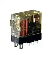


RJ1S-CLD-D24
Power Relay, SPDT, 24 VDC, 12 A, RJ Series, Socket, Non Latching
- Manufacturer: IDEC
- Product type: Power Relays
- SVHC: No SVHC (15-Jan-2019)
- Coil Type: Non Latching
- Coil Voltage: 24VDC
- Product Range: RJ Series
- Relay Mounting: Socket
- Coil Resistance: 1.08kohm
- Contact Current: 12A
- Relay Terminals: Plug In
- Contact Material: Silver Nickel Alloy
- Contact Voltage VAC: 250V
- Contact Voltage VDC: 30V
- Contact Configuration: SPDT
| Delivery and price | |
|---|---|
| Units per pack | 50 |
| Price | 6.49 € |
| Current stock | 10+ |
| Lead time | 30 days |
## Slim Power Relays ## RJ Series ## Large Switching Capacity Highly conductive materials ensure stable electric conduction of current. **==> picture [203 x 126] intentionally omitted <==** **----- Start of picture text -----**<br> Large Switching Capacity (maximum allowable switching current)<br>12A 8A<br>10A<br>5A<br>RJ1 Competitors (Note) RJ2 Competitors (Note)<br>Note:<br>According to published specifications in other manufacturers’ catalogs.<br>**----- End of picture text -----**<br> ## Excellent Durability Our unique return spring structure provides improved durability and reliability of all mechanical parts. ## Compact and rugged power relays. Large switching capacity. Plug-in terminal relays ideal for various applications such as control panels and machine tools. **==> picture [199 x 123] intentionally omitted <==** **----- Start of picture text -----**<br> Long Mechanical Life<br>AC Coil DC Coil<br>30 million 50 million<br>operations minimum operations minimum<br>10 million 20 million<br>operations operations<br>RJ Competitors (Note) RJ Competitors (Note)<br>Note: According to published specifications in other manufacturers’ catalogs.<br>3 times 2.5 times<br>more! more<br>**----- End of picture text -----**<br> ## High Visibility LED Indicator • See website for details on approvals and standards. • Lloyd Register type approved. IDEC’s Unique Light Guide Structure. An RJ relay can be easily identified with the illuminating LED. IEC-compliant Green Indication. **==> picture [200 x 29] intentionally omitted <==** **----- Start of picture text -----**<br> Light a<br>Guide<br>IEC-compliant Green Indication<br>**----- End of picture text -----**<br> ## Wide variety of models Diode, reverse polarity diode, and RC circuits are available. Wide variety of AC/DC coil voltages. For more information, visit http://apac.idec.com **For more information, visit https://www.idec-emea.com** H-007 Switches & Pilot Lights Control Boxes Emergency Stop Switches Enabling Switches Safety Products Explosion Proof Terminal Blocks Relays & Sockets Circuit Protectors Power Supplies LED Illumination Controllers Operator Interfaces Sensors AUTO-ID - RJ Series Slim Power Relays - ee **==> picture [68 x 9] intentionally omitted <==** **----- Start of picture text -----**<br> Coil Voltage Code ∗<br>**----- End of picture text -----**<br> ## Plug-in Terminal |Shape|1-pole: With forward polarity diode<br>(with LED indicator)<br>2-pole: Standard (with LED Indicator)|1-pole: With forward polarity diode<br>(with LED indicator)<br>2-pole: Standard (with LED Indicator)|1-pole: With forward polarity diode<br>(with LED indicator)<br>2-pole: Standard (with LED Indicator)|1-pole: With forward polarity diode<br>(with LED indicator)<br>2-pole: Standard (with LED Indicator)| |---|---|---|---|---| |Style|1-pole (SPDT)||2-pole (DPDT)|| ||Part No.|Code:|Part No.|Code:| |Standard<br>(with LED Indicator)|RJ1S-CL-|A12,A24,A100,A110|RJ2S-CL-|A12,A24,A100,A110| |||A200,A220||A200,A220| |||D5,D6,D12,D24,D48||D5,D6,D12,D24,D48| |||D100||D100| |Simple<br>(without LED Indicator)|RJ1S-C-|A12,A24,A100,A110|RJ2S-C-|A12,A24,A100,A110| |||A200,A220||A200,A220| |||D5,D6,D12,D24,D48||D5,D6,D12,D24,D48| |||D100||D100| |With forward polarity diode<br>(with LED indicator)|RJ1S-CLD-|D5,D6,D12,D24,D48|RJ2S-CLD-|A12,A24,A100,A110| |||D100||A200,A220| |With forward polarity diode<br>(without LED indicator)|RJ1S-CD-|D5,D6,D12,D24,D48|RJ2S-CD-|D5,D6,D12,D24,D48| |||D100||D100| |With reverse polarity diode<br>(with LED indicator)|RJ1S-CLD1-|D5,D6,D12,D24,D48|RJ2S-CLD1-|D5,D6,D12,D24,D48| |||D100||D100| |With reverse polarity diode<br>(without LED indicator)|RJ1S-CD1-|D5,D6,D12,D24,D48|RJ2S-CD1-|D5,D6,D12,D24,D48| |||D100||D100| |With RC<br>(with LED indicator)|RJ1S-CLR-|A12,A24,A100,A110|RJ2S-CLR-|A12,A24,A100,A110| |||A200,A220||A200,A220| |With RC<br>(without LED indicator)|RJ1S-CR-|A12,A24,A100,A110|RJ2S-CR-|A12,A24,A100,A110| |||A200,A220||A200,A220| • Other coil voltages available (A115, A120, A230, A240) APEM Relays Sockets DIN Rail Products ## Contact Ratings |No. of<br>Poles|Contact|Allowable Contact Power|Allowable Contact Power|Rated Load|Rated Load|Rated Load|Allowable<br>Switching<br>Current|Allowable<br>Switching<br>Voltage|Minimum Applicable<br>Load (Note)| |---|---|---|---|---|---|---|---|---|---| |||Resistive Load|Inductive Load|Voltage|Resistive<br>Load|Inductive Load<br>cos ø = 0.3<br>L/R = 7 ms|||| |1<br>~~SSS~~|NO|3000VA AC<br>360W DC|1875VA AC<br>180W DC|250V AC|12A|7.5A|12A<br>~~SSS~~|250V AC<br>125V DC<br>~~SSS~~|5V DC, 100 mA<br>(reference value)<br>~~SSS~~| |||||30V DC|12A|6A|||| ||NC<br>~~SSS~~|3000VA AC<br>180W DC<br>~~SSS~~|1875VA AC<br>90W DC<br>~~SSS~~|250V AC|12A|7.5A|||| |||||30V DC<br>~~SSS~~|6A<br>~~SSS~~|3A<br>~~SSS~~|||| |2<br>~~SSS~~|NO<br>~~SSS~~|2000VA AC<br>240W DC<br>~~SSS~~|1000VA AC<br>120W DC<br>~~SSS~~|250V AC<br>~~SSS~~|8A<br>~~SSS~~|4A<br>~~SSS~~|8A<br>~~SSS~~|250V AC<br>125V DC<br>~~SSS~~|5V DC, 10 mA<br>(reference value)<br>~~SSS~~| |||||30V DC<br>~~SSS~~|8A<br>~~SSS~~|4A<br>~~SSS~~|||| ||NC<br>~~SSS~~|2000VA AC<br>120W DC<br>~~SSS~~|1000VA AC<br>60W DC<br>~~SSS~~|250V AC<br>~~SSS~~|8A<br>~~SSS~~|4A<br>~~SSS~~|||| |||||30V DC<br>~~SSS~~|4A<br>~~SSS~~|2A<br>~~SSS~~|||| RJ RU RV8H RL Note: Measured at operating frequency of 120 operations per minute. Failure rate level P. ## Approved Ratings |Voltage|UL|UL|UL|UL|CSA|CSA|CSA|CSA|CSA|CSA|CSA|CSA|VDE|VDE|VDE|VDE| |---|---|---|---|---|---|---|---|---|---|---|---|---|---|---|---|---| ||Resistive||||Resistive||||Inductive||||Resistive||AC-15, DC-13<br>(Note)|| ||RJ1||RJ2||RJ1||RJ2||RJ1||RJ2||RJ1|RJ2|RJ1|RJ2| ||NO|NC|NO|NC|NO|NC|NO|NC|NO|NC|NO|NC|NO|NO|NO|NO| |250V AC|12A|12A|8A|8A|12A|12A|8A|8A|7.5A|7.5A|4A|4A|12A|8A|6A|3A| |30V DC|12A|6A|8A|4A|12A|6A|8A|4A|6A|3A|4A|2A|12A|8A|2.5A|2A| Note: According to the utilization categories of IEC60947-5-1 Download catalogs and CAD from https://www.idec-emea.com Download catalogs and CAD from http://apac.idec.com H-008 RJ Series Slim Power Relays ## Coil Ratings APEM Switches & Pilot Lights Control Boxes Emergency Stop Switches Enabling Switches Safety Products Explosion Proof Terminal Blocks Relays & Sockets Circuit Protectors Power Supplies LED Illumination Controllers Operator Interfaces Sensors AUTO-ID Relays Sockets DIN Rail Products RJ RU RV8H RL |Rated Voltage|Rated Voltage||Without LED Indicator|Without LED Indicator|Without LED Indicator|With LED Indicator|With LED Indicator|With LED Indicator|Operating Characteristics<br>(against rated values at 20°C)|Operating Characteristics<br>(against rated values at 20°C)|Operating Characteristics<br>(against rated values at 20°C)|Power<br>Consumption| |---|---|---|---|---|---|---|---|---|---|---|---|---| |||Coil<br>Voltage<br>Code|Rated<br>Current (mA)<br>±15%(at 20°C)||Coil<br>Resistance (Ω)<br>10% t 20°C|Rated<br>Current (mA)<br>±15%(at 20°C)||Coil<br>Resistance (Ω)<br>±10% (at 20°C)|Minimum<br>Pickup<br>Voltage|Dropout<br>Voltage|Maximum<br>Allowable<br>Voltage<br>(Note)|| ||||50 Hz|60 Hz|± (a )|50 Hz|60 Hz|||||| |AC<br>50/60 Hz|12V AC|A12|87.3|75.0|62.5|91.1|78.8|62.5|80%<br>maximum|30%<br>minimum|140%|Approx.<br>0.9 VA (60Hz)| ||24V AC|A24|43.9|37.5|243|47.5|41.1|243||||| ||110V AC|A110|9.6|8.2|5270|9.5|8.1|5270||||| ||115V AC|A115|9.1|7.8|6030|9.0|7.7|6030||||| ||120V AC|A120|8.8|7.5|6400|8.7|7.4|6400||||| ||220V AC|A220|4.8|4.1|21530|4.8|4.1|21530||||| ||230V AC|A230|4.6|3.9|24100|4.6|3.9|24100||||| ||240V AC|A240|4.3|3.7|25570|4.3|3.7|25570||||| |DC|5V|D5|106||47.2|110||47.2|70%<br>maximum|10%<br>minimum|170%|Approx.<br>0.53W| ||6V|D6|88.3||67.9|92.2||67.9||||| ||12V|D12|44.2||271|48.0||271||||| ||24V|D24|22.1||1080|25.7||1080||||| ||48V|D48|11.0||4340|10.7||4340||||| ||100-110V|D100|5.3-5.8||18870|5.2-5.7||18870|||160%|| Note: Maximum allowable voltage is the maximum voltage that can be applied to relay coils. ## Specifications |Specifications|Specifications||| |---|---|---|---| |Model||RJ1S|RJ2S| |Number of Poles||1-pole|2-pole| |Contact Confguration||SPDT|DPDT| |Contact Material||Silver-nickel alloy|| |Degree of Protection||IP40|| |Contact Resistance (initial value) (*1)||50 mΩ maximum|| |Operate Time (*2)||15 ms maximum|| |Release Time (*2)||10 ms maximum (with diode/with RC: 20 ms maximum)|| |Dielectric<br>Strength|Between contact and coil|5000V AC, 1 minute|5000V AC, 1 minute| ||Between contacts of the same pole|1000V AC, 1 minute|1000V AC, 1 minute| ||Between contacts of different poles|—|3000V AC, 1 minute| |Vibration<br>Resistance|Operating extremes|10 to 55 Hz, amplitude 0.75 mm|| ||Damage limits|10 to 55 Hz, amplitude 0.75 mm|| |Shock<br>Resistance|Operating extremes|NO contact: 200 m/s2, NC contact: 100 m/s2|| ||Damage limits|1000 m/s2|| |Electrical Life (rated load)||AC load:<br>200,000 operations minimum (operation frequency 1800 operations per hour)<br>DC load:<br>100,000 operations minimum(operation frequency1800 operationsper hour)|| |Mechanical Life (no load)||AC coil:<br>30,000,000 operations minimum (operation frequency 18,000 operations per hour)<br>DC coil:<br>50,000,000 operations minimum(operation frequency18,000 operationsper hour)|| |Operating Temperature (*3)||–40 to +70°C (no freezing)|| |Operating Humidity||5 to 85% RH (no condensation)|| |Weight (approx.)||19g|| Note: Above values are initial values. - *1) Measured using 5V DC, 1A voltage drop method. ## Relay Coil Tape Color - *2) Measured at the rated voltage (at 20°C), excluding contact bounce time. **==> picture [156 x 14] intentionally omitted <==** **----- Start of picture text -----**<br> Coil Voltage Coil Color<br>**----- End of picture text -----**<br> - *3) 100% rated voltage. |Coil Voltage|Coil Color| |---|---| ||| |12V AC|Yellow| |24V AC|White| |110V AC|Clear| |115V|Yellow| |120V AC|Blue| |220V AC|Black| |230V AC|Yellow| |240V AC|Red| |5V DC|Yellow| |6V DC|Yellow| |12V DC|Yellow| |24V DC|Green| |48V DC|Yellow| |100-110V DC|Yellow| ## Applicable Socket |Terminal|Part No.|Part No.|Page| |---|---|---|---| ||RJ1S(1-pole)|RJ2S(2-pole)|| |Standard Screw Terminal|SJ1S-05B|SJ2S-05B|H-043| |Finger-safe Screw Terminal|SJ1S-07L|SJ2S-07L|| |Push-in Terminal|SJ1S-21L|SJ2S-21L|| For more information, visit http://apac.idec.com **For more information, visit https://www.idec-emea.com** H-009 RJ Series Slim Power Relays RJ RU RV8H RL ## Dimensions **==> picture [327 x 160] intentionally omitted <==** **----- Start of picture text -----**<br> RJ1S RJ2S-CL<br>0.5 0.5 0.5 2.6<br>4.8 4.8 2.6<br>31.1 31.1<br>28.8 28.8<br>ø1.8 × 3 hole<br>ø1.2 × 3 hole<br>27.0 28.0 27.0<br>5.0 6.0<br>12.7 0.5 12.7<br>**----- End of picture text -----**<br> All dimensions in mm. ## RJ2S-CL- Standard (w/LED Indicator) ## RJ1S-CL- Standard (w/LED Indicator) **==> picture [206 x 114] intentionally omitted <==** **----- Start of picture text -----**<br> 1 1<br>(A1) (A1)<br>2(12) 3(11) 4(14) 2(12) 3(11) 4(14)<br>(A2)8 7(22) 6(21) 5(24) (A2)8 7(22) 6(21) 5(24)<br>Coil voltage 24V AC/DC and below Coil voltage greater than 24V AC/DC<br>RJ2S-C- Simple<br>1<br>(A1)<br>2(12) 3(11) 4(14)<br>8<br>(A2) 7(22) 6(21) 5(24)<br>**----- End of picture text -----**<br> **==> picture [206 x 111] intentionally omitted <==** **----- Start of picture text -----**<br> 1 1<br>(A1) (A1)<br>2(12) 4(11) 3(14) 2(12) 4(11) 3(14)<br>5 5<br>(A2) (A2)<br>Coil voltage 24V AC/DC and below Coil voltage greater than 24V AC/DC<br>RJ1S-C- Simple<br>1<br>(A1)<br>2(12) 4(11) 3(14)<br>5<br>(A2)<br>**----- End of picture text -----**<br> ## RJ2S-CLD- With Diode (w/LED Indicator) ## RJ1S-CLD- With Diode (w/LED Indicator) **==> picture [206 x 260] intentionally omitted <==** **----- Start of picture text -----**<br> 1 1<br>(A1) – (A1) –<br>5 + 2(12) 4(11) 3(14) 5 + 2(12) 4(11) 3(14)<br>(A2) (A2)<br>Coil voltage 24V DC and below Coil voltage greater than 24V DC<br>RJ1S-CD- With Diode<br>1<br>(A1) –<br>5 + 2(12) 4(11) 3(14)<br>(A2)<br>RJ1S-CLD1- With Diode (w/LED Indicator)<br>1 1<br>(A1) + (A1) +<br>5 – 2(12) 4(11) 3(14) 5 – 2(12) 4(11) 3(14)<br>(A2) (A2)<br>Coil voltage 24V DC and below Coil Voltage greater than 24V DC<br>RJ1S-CD1- With Diode<br>1<br>(A1) +<br>5 – 2(12) 4(11) 3(14)<br>(A2)<br>**----- End of picture text -----**<br> **==> picture [206 x 257] intentionally omitted <==** **----- Start of picture text -----**<br> (A1)1 – (A1)1 –<br>2(12) 3(11) 4(14) 2(12) 3(11) 4(14)<br>(A2)8 + 7(22) 6(21) 5(24) (A2)8 + 7(22) 6(21) 5(24)<br>Coil voltage 24V DC and below Coil voltage greater than 24V DC<br>RJ2S-CD- With Diode<br>1<br>(A1) –<br>2(12) 3(11) 4(14)<br>8 +<br>(A2) 7(22) 6(21) 5(24)<br>RJ2S-CLD1- With Diode (w/LED Indicator)<br>1 1<br>(A1) + (A1) +<br>2(12) 3(11) 4(14) 2(12) 3(11) 4(14)<br>(A2)8 – 7(22) 6(21) 5(24) (A2)8 – 7(22) 6(21) 5(24)<br>Coil voltage 24V DC and below Coil voltage greater than 24V DC<br>RJ2S-CD1- With Diode<br>1<br>(A1) +<br>2(12) 3(11) 4(14)<br>8 –<br>(A2) 7(22) 6(21) 5(24)<br>**----- End of picture text -----**<br> ## RJ1S-CLR- With RC (w/LED Indicator) ## RJ2S-CLR- With RC (w/LED Indicator) **==> picture [190 x 107] intentionally omitted <==** **----- Start of picture text -----**<br> 1 1<br> (A1) (A1)<br>2(12) 4(11) 3(14) 2(12) 4(11) 3(14)<br>5 5<br> (A2) (A2)<br>Coil voltage 24V AC and below Coil voltage greater than 24V AC<br>RJ1S-CR- With RC<br>1<br>(A1)<br>2(12) 4(11) 3(14)<br>5<br>(A2)<br>**----- End of picture text -----**<br> **==> picture [188 x 107] intentionally omitted <==** **----- Start of picture text -----**<br> 1 1<br>(A1) (A1)<br>2(12) 3(11) 4(14) 2(12) 3(11) 4(14)<br>8 8<br>(A2) 7(22) 6(21) 5(24) (A2) 7(22) 6(21) 5(24)<br>Coil voltage 24V AC and below Coil voltage greater than 24V AC<br>RJ2S-CR- With RC<br>1<br>(A1)<br>2(12) 3(11) 4(14)<br>8<br>(A2) 7(22) 6(21) 5(24)<br>**----- End of picture text -----**<br> APEM Switches & Pilot Lights Control Boxes Emergency Stop Switches Enabling Switches Safety Products Explosion Proof Terminal Blocks Relays & Sockets Circuit Protectors Power Supplies LED Illumination Controllers Operator Interfaces Sensors AUTO-ID Relays Sockets DIN Rail Products Download catalogs and CAD from https://www.idec-emea.com Download catalogs and CAD from http://apac.idec.com H-010 RJ Series Slim Power Relays APEM Switches & Pilot Lights Control Boxes Emergency Stop Switches Enabling Switches Safety Products Explosion Proof Terminal Blocks Relays & Sockets Circuit Protectors Power Supplies LED Illumination Controllers Operator Interfaces Sensors AUTO-ID Sockets DIN Rail Products RJ RU RV8H ## Electrical Life Curve RJ1 **==> picture [216 x 311] intentionally omitted <==** **----- Start of picture text -----**<br> 500<br>250V AC Resistive Load<br>100<br>30V DC inductive load 30V DC resistive load (NO contact)<br>(NC contact)<br>250V AC inductive load<br>10<br>30V DC resistive load (NC contact)<br>30V DC inductive load (NO contact)<br>1<br>0.1 1 12<br>Load Current (A)<br>Maximum Switching Capacity<br>AC resistive<br>load AC inductive<br>load<br>10<br>DC<br>resistive load<br>(NO contact)<br>DC resistive load (NC contact)<br>1 DC inductive load (NO contact)<br>DC inductive load<br>(NC contact)<br>0.1<br>1 10 100 250<br>Load Voltage (V)<br>Life (× 10,000 operations)<br>Load Current (A)<br>**----- End of picture text -----**<br> ## Maximum Switching Capacity RJ1 ## RJ2 **==> picture [217 x 118] intentionally omitted <==** **----- Start of picture text -----**<br> 500<br>250V AC Resistive Load<br>100<br>30V DC resistive load (NO contact)<br>30V DC inductive load<br>(NC contact)<br>250V AC inductive load<br>10<br>30V DC resistive load (NC contact)<br>30V DC inductive load (NO contact)<br>1<br>0.1 1 8<br>Load Current (A)<br>Life (×10,000 operations)<br>**----- End of picture text -----**<br> **==> picture [14 x 8] intentionally omitted <==** **----- Start of picture text -----**<br> RJ2<br>**----- End of picture text -----**<br> **==> picture [130 x 129] intentionally omitted <==** **----- Start of picture text -----**<br> AC resistive<br>load AC inductive<br>10 load<br>DC<br>resistive load<br>(NO contact)<br>DC resistive load (NC contact)<br>1 DC inductive load (NO contact)<br>DC inductive load<br>(NC contact)<br>0.1<br>1 10 100 250<br>Load Voltage (V)<br>Load Current (A)<br>**----- End of picture text -----**<br> ## Operating Temperature and Coil Temperature Rise Relays RL ## RJ1 **==> picture [486 x 286] intentionally omitted <==** **----- Start of picture text -----**<br> 130 [AC Coil (60 Hz)] 130 [AC Coil (50 Hz)] 130 [DC Coil]<br>120 120 120<br>110 110 110<br>100 100 100<br>90 90 90<br>8070 Load Current 12A × 1 pole 8070 Load Current 12A × 1 pole 8070<br>60 60 60 Load Current 12A × 1 pole<br>50 50 50<br>40 40 40<br>30 No Load Current 30 No Load Current 30<br>20 20 20<br>10 10 10 No Load Current<br>0 10 20 30 40 50 60 70 0 10 20 30 40 50 60 70 0 10 20 30 40 50 60 70<br>Ambient Temperature (°C) Ambient Temperature (°C) Ambient Temperature (°C)<br>AC Coil (60 Hz) AC Coil (50 Hz) DC Coil<br>130 130 130<br>120 120 120<br>110 110 110<br>100 100 100<br>90 90 90<br>80 80 80<br>Load Current 8A × 2 poles<br>70 70 Load Current 8A × 2 poles 70<br>60 60 60<br>50 50 50 Load Current 8A × 2 poles<br>40 40 40<br>30 No Load Current 30 No Load Current 30<br>20 20 20 No Load Current<br>10 10 10<br>0 10 20 30 40 50 60 70 0 10 20 30 40 50 60 70 0 10 20 30 40 50 60 70<br>Ambient Temperature (°C) Ambient Temperature (°C) Ambient Temperature (°C)<br>C)Temperature Rise (° C)Temperature Rise (° C)Temperature Rise (°<br>C)° C)°<br>C)°<br>Temperature Rise ( Temperature Rise (<br>Temperature Rise (<br>**----- End of picture text -----**<br> **==> picture [15 x 8] intentionally omitted <==** **----- Start of picture text -----**<br> RJ2<br>**----- End of picture text -----**<br> The above temperature rise curves show characteristics when 100% the rated coil voltage is applied. The slanted dashed line indicates allowable temperature rise for the coil at different ambient temperatures. For more information, visit http://apac.idec.com **For more information, visit https://www.idec-emea.com** H-011 RJ Series Slim Power Relays ## Safety Precautions Turn off the power to the relay before starting installation, removal, wiring, maintenance, and inspection of the relays. Failure to turn power off may cause electrical shock or fire hazard. requirements. Tighten the terminal screws on the relay socket to the proper tightening torque. Observe specifications and rated values, otherwise electri cal shock or fire hazard may be caused. Use wires of the proper size to meet the voltage and cur rent APEM ## Instructions ## Driving Circuit for Relays 1. To make sure of correct relay operation, apply rated volt age to the relay coil. 2. Input voltage for the DC coil: - A complete DC voltage is best for the coil power to make sure of stable relay operation. When using a power supply containing a ripple voltage, suppress the ripple factor within 5%. When power is supplied through a rectification circuit, the relay operating characteristics, such as pickup voltage and dropout voltage, depend on the ripple factor. Connect a smoothing capacitor for better operating char acteristics as shown below. **==> picture [228 x 82] intentionally omitted <==** **----- Start of picture text -----**<br> Pulsation<br>Smoothing<br>capacitor<br>+– R Relay Emin Emax Emean DC<br>Ripple factor (%) = Emax – Emin ×100%<br>Emean<br>Emax = Maximum of pulsating current<br>Emin = Minimum of pulsating current<br>Emean = DC mean value<br>**----- End of picture text -----**<br> 3. Operating the relay in synchronism with AC load: If the relay operates in synchronism with the AC power voltage of the load, the relay life may be reduced. If this is the case, select a relay in consideration of the required reliability for the load. Or, make the relay turn on and off irrespective of the AC power phase or near the point where the AC phase crosses zero voltage. **==> picture [228 x 46] intentionally omitted <==** **----- Start of picture text -----**<br> TE EAC<br>R<br>Load<br>EAC Vin<br>Vin<br>**----- End of picture text -----**<br> ## 4. Leakage current while relay is off: - When driving an element at the same time as the relay operation, a special consideration is needed for the circuit design. As shown in the incorrect circuit below, Leakage current (Io) flows through the relay coil while the relay is off. Leakage current causes the coil release failure or adversely affects the vibration resistance and shock resis tance. Design a circuit as shown in the correct example. **==> picture [222 x 57] intentionally omitted <==** **----- Start of picture text -----**<br> Incorrect Correct<br>R TE R<br>Io<br>**----- End of picture text -----**<br> 5. Surge suppression for transistor driving circuits: - When the relay coil is turned off, a high-voltage pulse is generated, causing the transistor to deteriorate and sometimes to break. Be sure to connect a diode to sup press the counter electromotive force. Then, the coil release time becomes slightly longer. To shorten the coil release time, connect a Zener diode between the collector and emitter of the transistor. Select a Zener diode with a Zener voltage slightly higher than the power voltage. **==> picture [94 x 53] intentionally omitted <==** **----- Start of picture text -----**<br> Counter emf<br>suppressing diode<br>+<br>– R Relay<br>**----- End of picture text -----**<br> Switches & Pilot Lights Control Boxes Emergency Stop Switches Enabling Switches Safety Products Explosion Proof Terminal Blocks Relays & Sockets Circuit Protectors Power Supplies LED Illumination Controllers Operator Interfaces Sensors AUTO-ID Relays Sockets DIN Rail Products RJ RU RV8H RL Download catalogs and CAD from https://www.idec-emea.com Download catalogs and CAD from http://apac.idec.com H-012 RJ Series Slim Power Relays ## Instructions ## Protection for Relay Contacts 1. The contact ratings show maximum values. Make sure that these values are not exceeded. When an inrush cur rent flows through the load, the contact may become welded. If this is the case, connect a contact protection circuit, such as a current limiting resistor. 2. Contact protection circuit: When switching an inductive load, arcing causes carbides to form on the contacts, resulting in an increased contact resistance. In consideration of contact reliability, contact life, and noise APEM Switches & Pilot Lights Control Boxes suppression, use of a surge absorbing cir cuit is recommended. Note that the release time of the load becomes slightly longer. Check the operation using the actual load. Incorrect use of a contact protection cir cuit will adversely affect switching characteristics. Four typical examples of contact protection circuits are shown in the following table: |Emergency<br>StopSwitches<br>Enabling<br>Switches<br>Safety Products<br>Explosion Proof<br>Terminal Blocks<br>Relays & Sockets<br>Circuit<br>Protectors<br>Power Supplies<br>LED Illumination<br>Controllers<br>Operator<br>Interfaces<br>Sensors<br>AUTO-ID<br>Relays<br>Sockets|<br>operation using the actual load. Incorrect use of a contact protectio<br>cir cuit will adversely affect switching characteristics. Four typical<br>examples of contact protection circuits are shown in the following<br>table:|<br>operation using the actual load. Incorrect use of a contact protectio<br>cir cuit will adversely affect switching characteristics. Four typical<br>examples of contact protection circuits are shown in the following<br>table:|<br>operation using the actual load. Incorrect use of a contact protectio<br>cir cuit will adversely affect switching characteristics. Four typical<br>examples of contact protection circuits are shown in the following<br>table:| |---|---|---|---| ||RC|Ind. Load<br>Power<br>C<br>R|This protection circuit can be used when<br>the load impedance is smaller than the RC<br>impedance in an AC load power circuit.<br>R: Resistor of approximately the same<br>resistance value as the load<br>C: 0.1 to 1 µF| |||Power<br>C<br>R<br>Ind. Load|This protection circuit can be used for both AC<br>and DC load power circuits.<br>R: Resistor of approximately the same<br>resistance value as the load<br>C: 0.1 to 1 µF| ||Diode|Power<br>+<br>–<br>D<br>Ind. Load|This protection circuit can be used for DC load<br>power circuits. Use a diode with the following<br>ratings.<br>Reverse withstand voltage:<br>Power voltage of the load circuit × 10<br>Forward current:<br>More than the load current| ||Varistor|Power<br>Ind. Load<br>Varistor|This protection circuit can be used for both AC<br>and DC load power circuits.<br>For a best result, when using on a power<br>voltage of 24 to 48V AC/DC, connect a varistor<br>across the load. When using on a power<br>voltage of 100 to 240V AC/DC, connect a<br>varistor across the contacts.| ## Other Precautions 1. General notice: - •To maintain the initial characteristics, do not drop the relay or shock the relay. - •The relay cover cannot be removed from the base during normal operation. To maintain the initial characteristics, do not remove the relay cover. - •Use the relay in environments free from condensation of dust, sulfur dioxide (SO2), and hydrogen sulfide (H2S). - •Make sure that the coil voltage does not exceed the appli cable coil voltage range. 2. Connecting outputs to electronic circuits: - When the output is connected to a load which responds very quickly, such as an electronic circuit, contact bounc ing causes incorrect operation of the load. Take the follow ing measures into consideration. a) Connect an integral circuit. - b) Suppress the pulse voltage due to bouncing within the noise margin of the load. 3. UL- and CSA-approved ratings may differ from product rated values determined by IDEC. 4. Do not use relays in the vicinity of strong magnetic field as this may affect relay operation. - •DC diode type has polarity. - •The surge absorbing element on AC relays with RC or DC relays with diode is provided to absorb the counter electro motive force generated by the coil. When the relay is sub ject to an excessive external surge voltage, the surge absorbing element may be damaged. Add another surge absorbing provision to the relay to prevent damage. **==> picture [285 x 111] intentionally omitted <==** **----- Start of picture text -----**<br> DIN Rail<br>Products 3. Do not use a contact protection circuit as shown below:<br>This protection circuit is very effective in arc sup pression<br>when opening the contacts. But, the capac itor is charged<br>C Load while the contacts are opened. When the contacts are closed,<br>RJ Power the capacitor is discharged through the contacts, increasing<br>the possibility of contact welding.<br>RU<br>This protection circuit is very effective in arc sup pression<br>RV8H PowerC Load when opening the contacts. But, when the contacts are closed, a current flows to charge the capacitor, causing<br>RL contact welding.<br>**----- End of picture text -----**<br> Generally, switching a DC inductive load is more difficult than switching a DC resistive load. Using an appropriate arc suppressor, however, will improve the switching char acteristics of a DC inductive load. SAPEN01A RJ October 2021 For more information, visit http://apac.idec.com **For more information, visit https://www.idec-emea.com** H-013 ## Ordering Terms and Conditions ## Thank you for using IDEC Products. By purchasing products listed in our catalogs, datasheets, and the like (hereinafter referred to as “Catalogs”) you agree to be bound by these terms and conditions. Please read and agree to the terms and conditions before placing your order. ## 1. Notes on contents of Catalogs - (1) Rated values, performance values, and specification values of IDEC products listed in this Catalog are values acquired under respective conditions in independent testing, and do not guarantee values gained in combined conditions. - Also, durability varies depending on the usage environment and usage conditions. - (2) Reference data and reference values listed in Catalogs are for reference purposes only, and do not guarantee that the product will always operate appropriately in that range. - (3) The specifications / appearance and accessories of IDEC products listed in Catalogs are subject to change or termination of sales without notice, for improvement or other reasons. - (4) The content of Catalogs is subject to change without notice. ## 2. Note on applications - (1) If using IDEC products in combination with other products, confirm the applicable laws / regulations and standards. Also, confirm that IDEC products are compatible with your systems, machines, devices, and the like by using under the actual conditions. IDEC shall bear no liability whatsoever regarding the compatibility with IDEC products. - (2) The usage examples and application examples listed in Catalogs are for reference purposes only. Therefore, when introducing a product, confirm the performance and safety of the instruments, devices, and the like before use. Furthermore, regarding these examples, IDEC does not grant license to use IDEC products to you, and IDEC offers no warranties regarding the ownership of intellectual property rights or non-infringement upon the intellectual property rights of third parties. - (3) When using IDEC products, be cautious when implementing the following. i. Use of IDEC products with sufficient allowance for rating and performance - ii. Safety design, including redundant design and malfunction prevention design that prevents other danger and damage even in the event that an IDEC product fails - iii. Wiring and installation that ensures the IDEC product used in your system, machine, device, or the like can perform and function according to its specifications - (4) Continuing to use an IDEC product even after the performance has deteriorated can result in abnormal heat, smoke, fires, and the like due to insulation deterioration or the like. Perform periodic maintenance for IDEC products and the systems, machines, devices, and the like in which they are used. - (5) IDEC products are developed and manufactured as general-purpose products for general industrial products. They are not intended for use in the following applications, and in the event that you use an IDEC product for these applications, unless otherwise agreed upon between you and IDEC, IDEC shall provide no guarantees whatsoever regarding IDEC products. - i. Use in applications that require a high degree of safety, including nuclear power control equipment, transportation equipment (railroads / airplanes / ships / vehicles / vehicle instruments, etc.), equipment for use in outer space, elevating equipment, medical instruments, safety devices, or any other equipment, instruments, or the like that could endanger life or human health - ii. Use in applications that require a high degree of reliability, such as provision systems for gas / waterworks / electricity, etc., systems that operate continuously for 24 hours, and settlement systems ## 3. Inspections We ask that you implement inspections for IDEC products you purchase without delay, as well as thoroughly keep in mind management/maintenance regarding handling of the product before and during the inspection. ## 4. Warranty - (1) Warranty period The warranty period for IDEC products shall be one (1) year after purchase or delivery to the specified location. However, this shall not apply in cases where there is a different specification in the Catalogs or there is another agreement in place between you and IDEC. - (2) Warranty scope Should a failure occur in an IDEC product during the above warranty period for reasons attributable to IDEC, then IDEC shall replace or repair that product, free of charge, at the purchase location / delivery location of the product, or an IDEC service base. However, failures caused by the following reasons shall be deemed outside the scope of this warranty. - i. The product was handled or used deviating from the conditions / environment listed in the Catalogs - ii. The failure was caused by reasons other than an IDEC product - iii. Modification or repair was performed by a party other than IDEC - iv. The failure was caused by a software program of a party other than IDEC - v. The product was used outside of its original purpose - vi. Replacement of maintenance parts, installation of accessories, or the like was not performed properly in accordance with the user’s manual and Catalogs vii. The failure could not have been predicted with the scientific and technical standards at the time when the product was shipped from IDEC viii. The failure was due to other causes not attributable to IDEC (including cases of force majeure such as natural disasters and other disasters) - Furthermore, the warranty described here refers to a warranty on the IDEC product as a unit, and damages induced by the failure of an IDEC product are excluded from this warranty. ## 5. Limitation of liability The warranty listed in this Agreement is the full and complete warranty for IDEC products, and IDEC shall bear no liability whatsoever regarding special damages, indirect damages, incidental damages, or passive damages that occurred due to an IDEC product. ## 6. Service scope The prices of IDEC products do not include the cost of services, such as dispatching technicians. Therefore, separate fees are required in the following cases. - (1) Instructions for installation / adjustment and accompaniment at test operation (including creating application software and testing operation, etc.) - (2) Maintenance inspections, adjustments, and repairs - (3) Technical instructions and technical training - (4) Product tests or inspections specified by you The above content assumes transactions and usage within your region. Please consult with an IDEC sales representative regarding transactions and usage outside of your region. Also, IDEC provides no guarantees whatsoever regarding IDEC products sold outside your region. - iii. Use in applications where the product may be handled or used deviating from the specifications or conditions / environment listed in the Catalogs, such as equipment used outdoors or applications in environments subject to chemical pollution or electromagnetic interference If you would like to use IDEC products in the above applications, be sure to consult with an IDEC sales representative. **Head Office** 6-64, Nishi-Miyahara-2-Chome, Yodogawa-ku, Osaka 532-0004, Japan **USA** IDEC Corporation **Singapore** IDEC Izumi Asia Pte. Ltd. **EMEA** APEM SAS **Thailand** IDEC Asia (Thailand) Co., Ltd. **Singapore** IDEC Izumi Asia Pte. Ltd. **Thailand** IDEC Asia (Thailand) Co., Ltd. **India** IDEC Controls India Private Ltd. Specifications and other descriptions in this brochure are subject to change without notice. 2021 IDEC Corporation, All Rights Reserved. ## **www.idec.com** **China** IDEC (Shanghai) Corporation **Japan** IDEC Corporation IDEC Izumi (H.K.) Co., Ltd. **Taiwan** IDEC Taiwan Corporation **==> picture [95 x 33] intentionally omitted <==**
Updated at June 10, 2026
Founded in 1945, IDEC is a globally recognized leader in industrial automation, machine safety, and control products. Renowned for pioneering innovations in Human-Machine Interface (HMI) systems, the company is dedicated to creating a safe and efficient harmony between advanced workplace technology and human operators. At the core of IDEC’s extensive portfolio is a comprehensive selection of high-performance relays designed for demanding industrial environments. This includes a broad range of electromechanical power relays, solid-state relays, contactors, and critical safety relays, supported by a wide array of specialized relay accessories to ensure reliable and efficient switching. Beyond switching components, IDEC provides complete solutions for modern control panels and automated systems. Their robust engineering extends to advanced panel displays and instrumentation, precision light sensors, and dependable AC/DC power converters. With additional offerings in industrial switches, visual signaling units, and DIN rail terminal blocks, IDEC equips engineers with the high-quality components required to build secure, next-generation automation infrastructure.
About Novapart
Novapart is a B2B electronic component broker specialising in stock shortages and cost reduction. We source hard-to-find parts and identify compliant alternatives across a catalogue of 410,000+ components from 500+ manufacturers.
Learn more →Stock Shortage Specialist
When a component is unavailable, discontinued or has an unacceptable lead time, we tap into our network of vetted European and Asian distributors to source what you need — without compromising on quality or traceability.
Request a quote →Compliant Alternatives
We identify pin-to-pin, electrically equivalent substitutes that meet the same certifications (RoHS, AEC-Q100, REACH) as your original specification — validated against datasheets, not just part numbers. Often at a lower cost.
BOM Analysis service →