
Image not available
Illustrative purposes only


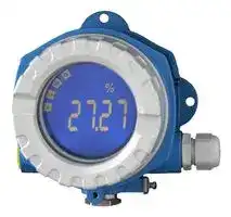
RIA14-BD3C
Display, ATEX II2G Ex db IIC T6 Gb, Field, Die-Cast Aluminium, M20 Female Thread
⚠️ Reference pricing provided. In case of supply shortages, we will connect you with our trusted procurement partners to ensure your project's continuity.
- Manufacturer: ENDRESS+HAUSER
- Product type: Digital Panel Meters
- SVHC: To Be Advised
- Meter Range: 4mA to 20mA
- Digit Height: 20.5mm
- Product Range: RIA14 Series
- Meter Function: Current
- Panel Cutout Width: -
- Supply Voltage Max: -
- Supply Voltage Min: -
- Panel Cutout Height: -
- No. of Digits / Alpha: 5
- Operating Temperature Max: 80°C
- Operating Temperature Min: -40°C
| Delivery and price | |
|---|---|
| Units per pack | 1 |
| Price | 578.84 € |
| Current stock | 10+ |
| Lead time | 30 days |
Datasheet

TI00143R/09/EN/05.23-00 71615258 2023-01-30 Products Solutions Services ## Technical Information RIA14 ## Loop-powered field indicator ## Application - Oil & gas - Petrochemicals - Plant and apparatus engineering - Free-space applications - Laboratory equipment - Process recording and monitoring - Optional: Stainless steel housing ## Your benefits - Loop-powered indicator in single-compartment housing - 5-digit LC display, digit height 20.5 mm (0.8 in) - Backlit display, pluggable in 90 ° steps - Trend bar graph in increments of 10 % - Measuring range display from –19 999 to 99 999 - Digital limit switch - Freely programmable units - 3-key operation - International approvals ATEX, IECEx, FM, CSA, TIIS, UK CA, UL listed, BV and marine approvals - 3 cable entries - Configuration via interface with FieldCare PC software - Configuration without power supply using setup box RIA14 ## Function and system design ## Measuring principle **==> picture [371 x 175] intentionally omitted <==** **----- Start of picture text -----**<br> Hazardous area Non-hazardous<br>Zone 1, 2 EX EX area<br>Zone 21, 22<br>30 40 50<br>20<br>10<br>0<br>Transmitter<br>Power supply<br>4...20 mA<br>**----- End of picture text -----**<br> **==> picture [22 x 4] intentionally omitted <==** **----- Start of picture text -----**<br> A0051968<br>**----- End of picture text -----**<br> **==> picture [187 x 9] intentionally omitted <==** **----- Start of picture text -----**<br> 1 Example of an application of the field indicator<br>**----- End of picture text -----**<br> The indicator captures an analog measuring signal and presents it on the display. The LC display shows the current measured value in digital form and as a bar graph indicating a limit value violation. The indicator is looped into the 4 to 20 mA circuit and gets the required energy from there. ## Measuring system Microcontroller-controlled indicator in single-compartment field housing with backlit LC display. Configuration of the measuring range, decimal point and offset of the display can be conveniently performed via three keys in the device with the housing open or via a PC with the FieldCare PC software. ## Input Measured variable Current Measuring range 4 to 20 mA Reverse polarity protection Input signal • Voltage drop < 4 V at 3 to 22 mA • Max. voltage drop < 6 V at max. short-circuit current 200 mA ## Output ## Output signal Digital limit switch Passive, open collector: |Digital limit switch<br>Passive, open collector:|| |---|---| |Imax|200 mA| ||| |Umax|35 V| ||| |Ulow/max|< 2 V at 200 mA| Endress+Hauser 2 RIA14 Max. reaction time to 250 ms limit value Temperature range –20 to +80 °C (–4 to +176 °F) |Signal on alarm|•|No measured value visible in the LC display, no background illumination.| |---|---|---| ||•|Open collector inactive.| Transmission behavior The indicator allows the HART® transmission protocol to pass unimpeded. ## Power supply Terminal assignment **==> picture [387 x 273] intentionally omitted <==** **----- Start of picture text -----**<br> active<br>Open Collector<br>passive<br>loop power<br>1<br> + supply<br>3 [2] - loop power<br>supply<br> A0051890<br> 2 Terminal assignment of the field indicator<br>**----- End of picture text -----**<br> |Terminal|Terminal assignment|Input and output| |---|---|---| |+|Measuring signal (+) 4 to 20 mA|Signal input| |-|Measuring signal (-) 4 to 20 mA|Signal input| |1a, 1b|Terminal for further instruments|Support terminal| |2|Digital limit switch (collector)|Switch output| |3|Digital limit switch (emitter)|Switch output| Supply voltage Power is supplied via the 4 to 20 mA current loop. The device may only be powered by a power unit with an energy-limited circuit in accordance with UL/EN/IEC 61010-1, Section 9.4 and the requirements of Table 18. Voltage drop |Voltage drop|< 3.6 V at 3 to 22 mA| |---|---| |Max. voltage drop|< 6 V at max. short-circuit current 200 mA| Terminals Cables up to 2.5 mm[2] (14 AWG) max. plus ferrule Endress+Hauser 3 RIA14 ## Cable entries The following cable entries are available: • NPT 1/2 thread • M20 thread • G1/2 thread • 2x NPT1/2 gland + 1x dummy plug • 2x M20 gland + 1x dummy plug ## Performance characteristics |Reference conditions|T|25 °C (77 °F)| |---|---|---| |||| |Maximum measured error|< 0.1 % of scaled display range|| |Influence of ambient<br>temperature|Impact on accuracy when ambient temperature changes by 1 K (1.8 °F): 0.01 %<br>Mounting|| |Mounting location|Wall or pipe mounting (see "Accessories")|| |Orientation|No restrictions.<br>The orientation is determined by the legibility of the display.|| |Altitude|Up to 2 000 m (6 561.7 ft) above sea level<br>Environment|| |Ambient temperature range|–40 to +80 °C (–40 to +176 °F)<br>–20 to +80 °C (–4 to +176 °F) when using the open collector output<br>The display may react slowly at temperatures < –20 °C (–4 °F).<br>At temperatures < –30 °C (–22 °F) the readability of the display can no longer be guaranteed.|| |Storage temperature|–40 to 80 °C (–40 to 176 °F)|| |Electrical safety|As per IEC 61010-1,<br>UL 61010-1,<br>CSA C22.2 No. 1010.1-92|| |Climate class|As per IEC 60654-1, Class C|| |Degree of protection|IP 66/IP67, Type 4X (not assessed by UL)|| |Vibration resistance|3g at 2 to 150 Hz as per IEC 60068-2-6|| |Condensation|Permitted|| |Installation category|1 as per IEC 61010|| Endress+Hauser 4 RIA14 Pollution degree 2 Overvoltage category II Electromagnetic CE conformity compatibility (EMC) Electromagnetic compatibility in accordance with all the relevant requirements of the IEC/EN 61326 series and NAMUR Recommendation EMC (NE21). For details, refer to the Declaration of Conformity. Maximum measured error <1% of measuring range. Interference immunity as per IEC/EN 61326 series, industrial requirements Interference emission as per IEC/EN 61326 series, Class B equipment Connection of the functional grounding may be needed for functional purposes. Compliance with the electrical codes of individual countries is mandatory. ## Mechanical construction Design, dimensions Die-cast aluminum housing for general applications, or optional stainless steel housing ||132 (5.2)<br>135 (5.3)<br>112 (4.4)<br>166 (6.5)<br>106 (4.2)<br>121 (4.8)<br>121 (4.8)<br>�6.4<br>(0.25)|132 (5.2)<br>135 (5.3)<br>112 (4.4)<br>166 (6.5)<br>106 (4.2)<br>121 (4.8)<br>121 (4.8)<br>�6.4<br>(0.25)| |---|---|---| ||A0011152<br>_ 3_<br>_Dimensions in mm (in)_<br>• Aluminum housing for general applications or, optional stainless steel housing<br>• Electronics compartment and connection compartment in single-chamber housing<br>• Display can be fitted in steps of 90 °|| |Weight||| ||Aluminum housing|Approx. 1.6 kg (3.5 lb)| ||Stainless steel housing|Approx. 4.2 kg (3.5 lb)| |Materials|Housing|Nameplate| |---|---|---| ||Die-cast aluminum AlSi10Mg/ALSi12Mg with powder coating on<br>polyester base|Aluminum AIMgl, anodized in black| ||Stainless steel CF3M (316L)|Stainless steel 1.4404 (AiSi 316L)| |||| |Terminals|Cables up to 2.5 mm2(14 AWG) max. plus ferrule<br>Human interface|| |Operation concept|3-key operation (-/+/E) integrated in the device, access when housing is open|| Endress+Hauser 5 RIA14 Local operation **==> picture [208 x 146] intentionally omitted <==** **----- Start of picture text -----**<br> 1 6<br>5<br>2<br>1a 1b<br>4<br>3<br>**----- End of picture text -----**<br> **==> picture [22 x 4] intentionally omitted <==** **----- Start of picture text -----**<br> A0011157<br>**----- End of picture text -----**<br> - _ 4 LC display of the field indicator (backlit, fitted in steps of 90 °)_ - _1 Bar graph display_ - _1a Mark for underranging_ - _1b Mark for overranging 2 Measured value display, digit height 20.5 mm (0.8 in)_ - _3 14-segment display for units and messages_ - _4 "Programming locked_ _**'** symbol_ - _5 Unit "%"_ - _6 "Fault" warning icon_ - Display area - –19 999 to +99 999 - Offset - –19 999 to +99 999 - Signalization Overranging/underranging - Limit value over/under cut Limit value overranging/underranging ## Remote operation ## Configuration The device can be configured with the FieldCare PC software. FieldCare Device Setup is included in the scope of delivery of the Commubox FXA291 and TXU10-AC (see 'Accessories') or can be downloaded free of charge via www.endress.com. ## Interface Configuration interface at device; connection to PC via interface cable (see 'Accessories'). ## Configurable device parameters (selection) Measuring dimension, measuring ranges (linear/quadratic), setup lock via operator code, failsafe mode, digital filter (damping), offset, limit value (min/max/alarm), alarm limit values can be configured by the user Endress+Hauser 6 RIA14 **==> picture [387 x 198] intentionally omitted <==** **----- Start of picture text -----**<br> 1 2 3<br>USB<br> A0051931<br>**----- End of picture text -----**<br> - _ 5 Configuration via PC configuration software_ - _1 PC configuration software_ - _2 USB box configuration kit_ - _3 Field indicator_ ## Certificates and approvals Current certificates and approvals for the product are available at www.endress.com on the relevant product page: 1. Select the product using the filters and search field. 2. Open the product page. 3. Select Downloads. UL approval More information under UL Product iq™, search for keyword "E225237") ## Ordering information Detailed ordering information is available from your nearest sales organization www.addresses.endress.com or in the Product Configurator at www.endress.com: 1. Select the product using the filters and search field. 2. Open the product page. 3. Select Configuration. Product Configurator - the tool for individual product configuration - Up-to-the-minute configuration data - Depending on the device: Direct input of measuring point-specific information such as measuring range or operating language - Automatic verification of exclusion criteria - Automatic creation of the order code and its breakdown in PDF or Excel output format - Ability to order directly in the Endress+Hauser Online Shop ## Accessories Accessories currently available for the product can be selected via the Product Configurator at www.endress.com: 1. Select the product using the filters and search field. Endress+Hauser 7 RIA14 2. Open the product page. 3. Select Spare parts & Accessories. Communication-specific accessories |Designation|| |---|---| |Interface cable|Commubox TXU10 incl. FieldCare Device Setup and DTM Library| ||Commubox FXA291 incl. FieldCare Device Setup and DTM Library| ## Supplementary documentation The following types of documentation are available on the product pages and in the Download Area of the Endress+Hauser website (www.endress.com/downloads) (depending on the selected device version): |Document|Purpose and content of the document| |---|---| |Technical Information (TI)|Planning aid for your device<br>The document contains all the technical data on the device and provides<br>an overview of the accessories and other products that can be ordered for<br>the device.| |Brief Operating Instructions (KA)|Guide that takes you quickly to the 1st measured value<br>The Brief Operating Instructions contain all the essential information<br>from incoming acceptance to initial commissioning.| |Operating Instructions (BA)|Your reference document<br>The Operating Instructions contain all the information that is required in<br>various phases of the life cycle of the device: from product identification,<br>incoming acceptance and storage, to mounting, connection, operation<br>and commissioning through to troubleshooting, maintenance and<br>disposal.| |Description of Device Parameters<br>(GP)|Reference for your parameters<br>The document provides a detailed explanation of each individual<br>parameter. The description is aimed at those who work with the device<br>over the entire life cycle and perform specific configurations.| |Safety Instructions (XA)|Depending on the approval, Safety Instructions (XA) are supplied with the<br>device. The Safety Instructions are an integral part of the Operating<br>Instructions.<br>Information on the Safety Instructions (XA) that are relevant for<br>the device is provided on the nameplate.| |Supplementary device-dependent<br>documentation (SD/FY)|Always comply strictly with the instructions in the relevant<br>supplementary documentation. The supplementary documentation is an<br>integral part of the device documentation.| Endress+Hauser 8 *71615258* 71615258 www.addresses.endress.com
Updated at June 9, 2026
About Novapart
Novapart is a B2B electronic component broker specialising in stock shortages and cost reduction. We source hard-to-find parts and identify compliant alternatives across a catalogue of 410,000+ components from 500+ manufacturers.
Learn more →Stock Shortage Specialist
When a component is unavailable, discontinued or has an unacceptable lead time, we tap into our network of vetted European and Asian distributors to source what you need — without compromising on quality or traceability.
Request a quote →Compliant Alternatives
We identify pin-to-pin, electrically equivalent substitutes that meet the same certifications (RoHS, AEC-Q100, REACH) as your original specification — validated against datasheets, not just part numbers. Often at a lower cost.
BOM Analysis service →