
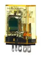


RH2B-UCDC24V
Power Relay, with Check Button, DPDT, 24 VDC, 10 A, RH Series, Socket, Non Latching
- Manufacturer: IDEC
- Product type: Power Relays
- SVHC: No SVHC (25-Jun-2025)
- Coil Type: Non Latching
- Coil Voltage: 24VDC
- Product Range: RH Series
- Relay Mounting: Socket
- Coil Resistance: 640ohm
- Contact Current: 10A
- Relay Terminals: Quick Connect
- Contact Material: Silver Cadmium Oxide
- Contact Voltage VAC: 110V
- Contact Voltage VDC: 30V
- Contact Configuration: DPDT
| Delivery and price | |
|---|---|
| Units per pack | 50 |
| Price | 8.5 € |
| Current stock | 10+ |
| Lead time | 30 days |
**Relays  & Sockets**

**RH**

## **RH Series Compact Power Relays**

## **Key features**

- SPDT through 4PDT, 10A contacts

- Compact power type relays

- Miniature power relays with a large capacity

- 10A contact capacity

- Compact size saves space

## **Part Number Selection**

||||||||Part Number|Part Number||
|---|---|---|---|---|---|---|---|---|---|
|Contact||||||Model|Blade<br>Terminal|PCB Terminal|Coil Voltage Code<br>**(Standard Stock in bold)**|
|SPDT|el||me|||Standard<br>With Indicator<br>With Check Button<br>With Indicator and Check Button|RH1B-U0<br>RH1B-UL0<br>RH1B-UC0<br>RH1B-ULC0|RH1V2-U0<br>—<br>—<br>—|AC6V, AC12V,**AC24V**, AC110V,**AC120V**,<br>AC220V,**AC240V**DC6V,**DC12V**,**DC24V**,<br>DC48V, DC110V|
|qua|ris}|||||Top Bracket Mounting<br>With Diode (DC coil only)|RH1B-UT0<br>RH1B-UD0|—<br>RH1V2-UD0|DC6V,**DC12V**,**DC24V**, DC48V, DC110V|
|||||||With Indicator and Diode (DC coil only)|RH1B-ULD0|—|**DC12V**,**DC24V**, DC48V, DC110V|
|DPDT<br>ue,|od’||SP||ap.|Standard<br>With Indicator<br>With Check Button<br>With Indicator and Check Button|RH2B-U0<br>RH2B-UL0<br>RH2B-UC0<br>RH2B-ULC0|RH2V2-U0<br>RH2V2-UL0<br>—<br>—|AC6V, AC12V,**AC24V**,**AC110-120V**,<br>**AC220-240V**<br>DC6V,**DC12V**,**DC24V**, DC48V, DC100-110V|
|Wow|COR|me||E|-|Top Bracket Mounting<br>With Diode (DC coil only)<br>With Indicator and Diode (DC coil only)|RH2B-UT0<br>RH2B-UD0<br>RH2B-ULD0|—<br>RH2V2-UD0<br>RH2V2-ULD0|DC6V,**DC12V**,**DC24V**, DC48V, DC100-110V|
|3PDT<br>=—|==|-|=|||Standard<br>With Indicator<br>With Check Button<br>With Indicator and Check Button|RH3B-U0<br>RH3B-UL0<br>RH3B-UC0<br>RH3B-ULC0|RH3V2-U0<br>RH3V2-UL0<br>—<br>—|AC6V, AC12V,**AC24V**, AC110V,**AC120V**,<br>AC220V,**AC240V**DC6V,**DC12V**,**DC24V**,<br>DC48V, DC110V|
|||||||Top Bracket Mounting|RH3B-UT0|—||
|||||||With Diode (DC coil only)<br>With Indicator and Diode (DC coil only)|RH3B-UD0<br>RH3B-ULD0|—<br>—|DC6V, DC12V, DC24V, DC48V, DC110V|
|4PDT<br>ie—<br>Chron <br>== :|—a<br> im<br>ASss<br>At‘afBa)|||||Standard<br>With Indicator<br>With Check Button<br>With Indicator and Check Button<br>Top Bracket Mounting|RH4B-U0<br>RH4B-UL0<br>RH4B-UC0<br>RH4B-ULC0<br>RH4B-UT0|RH4V2-U0<br>RH4V2-UL0<br>—<br>—<br>—|AC6V, AC12V,**AC24V**, AC110V,**AC120V**,<br>AC220V,**AC240V**DC6V,**DC12V**,**DC24V**, DC48V,<br>DC110V|
|||||||With Diode (DC coil only)<br>With Indicator and Diode (DC coil only)|RH4B-UD0<br>RH4B-ULD0|RH4V2-UD0<br>—|DC6V, DC12V, DC24V, DC48V, DC110V|


PCB terminal relays are designed to mount directly to a circuit board without any socket.

|**Ordering Information**<br>When ordering, specify the Part No. and coil voltage code:<br>(example)**RH3B-U       AC120V**<br>Part No.                         Coil Voltage Code|
|---|


1705151135

**800-262-IDEC** (4332) • USA & Canada

873

**Relays & Sockets**

**RH**

## **Sockets** (for Blade Terminal Models)

**==> picture [546 x 165] intentionally omitted <==**

**----- Start of picture text -----**<br>
||||||||
|---|---|---|---|---|---|---|
|Sockets|(for Blade Terminal Models)|
|Relays|Standard DIN Rail Mount|[1]|Finger-safe DIN Rail Mount|[1]|Through Panel Mount|PCB Mount|
|RH1B|SH1B-05|SH1B-O5C|SH1B-51|SH1B-62|
|RH2B|SH2B-05|SH2B-05C|SH2B-51|SH2B-62|1.|DIN Rail mount|
|socket comes with|
|A|
|RH3B|SH3B-05|SH3B-05C|SH3B-51|SH3B-62|two horseshoe|
|clips. Do not use|
|RH4B|SH4B-05|SH4B-05C|SH4B-51|SH4B-62|
|unless you plan to|
|insert pullover wire|
|spring. Replacement|
|horseshoe clip part|
|number is Y778-011.|
|Hold Down Springs & Clips|
|For DIN|For Through Panel &|

**----- End of picture text -----**<br>


**==> picture [531 x 129] intentionally omitted <==**

**----- Start of picture text -----**<br>
|||||||
|---|---|---|---|---|---|
|For DIN|For Through Panel &|
|Appearance|Item|Relay|
|Mount Socket|PCB Mount Socket|
|RH1B|SY2S-02F1|[2]|2.|Must use horseshoe clip when|
|mounting in DIN mount socket.|
|SN|RH2B|SY4S-02F1|[2]|A|Replacement horseshoe clip|
|Pullover Wire Spring|SY4S-51F1|
|RH3B|SH3B-05F1|[2]|part number is Y778-011.|
|3.|Two required per relay.|
|RH4B|SH4B-02F1|[2]|
|Leaf Spring (side latch)|RH1B, RH2B, RH3B, RH4B|SFA-202|[3]|SFA-302|[3]|
|Leaf Spring (top latch)|RH1B, RH2B, RH3B, RH4B|SFA-101|[3]|SFA-301|[3]|

**----- End of picture text -----**<br>


## **AC Coil Ratings**

**==> picture [7 x 22] intentionally omitted <==**

**==> picture [528 x 178] intentionally omitted <==**

**----- Start of picture text -----**<br>
|||||||||||||||||
|---|---|---|---|---|---|---|---|---|---|---|---|---|---|---|---|
|Rated Current (mA) ±15% at 20°C|Coil Resistance (Ω)|Operation Characteristics|
|Voltage|AC 50Hz|AC 60Hz|±10% at 20°C|(against rated values at 20ºC)|
|(V)|
|Max. Continuous|Pickup|Dropout|
|SPDT|DPDT|3PDT|4PDT|SPDT|DPDT|3PDT|4PDT|SPDT|DPDT|3PDT|4PDT|
|Applied Voltage|Voltage|Voltage|
|6|170|240|330|387|150|200|280|330|18.8|9.34|6.4|5.8|
|12|86|121|165|196|75|100|140|165|76.8|39.3|25.3|23.1|
|24|42|60.5|81|98|37|50|70|83|300|152|103|84.5|
|110|9.6|—|18.1|21.6|8.4|—|15.5|18.2|6,950|—|2,200|1,800|
|110-120|—|9.4-|—|—|—|8.0-9.2|—|—|—|—|—|—|110%|80%|30%|
|10.8|maximum|minimum|
|120|8.6|—|16.4|19.5|7.5|—|14.2|16.5|8,100|—|2770|2220|
|220|4.7|—|8.8|10.7|4.1|—|7.7|9.1|25,892|—|10,810|7,360|
|220-240|—|4.7-5.4|—|—|—|4.0-4.6|—|—|—|18,820|—|—|
|240|4.9|—|8.2|9.8|4.3|—|7.1|8.3|26,710|—|12,100|9,120|

**----- End of picture text -----**<br>


##

## **DC Coil Ratings**

**==> picture [519 x 124] intentionally omitted <==**

**----- Start of picture text -----**<br>
|||||||||||||||||
|---|---|---|---|---|---|---|---|---|---|---|---|---|---|---|---|
|Coil Resistance (Ω)|Operation Characteristics|
|Rated Current (mA) ±15% at 20°C|
|Voltage|±10% at 20°C|(against rated values at 20ºC)|
|(V)|Max. Continuous|Pickup|Dropout|
|SPDT|DPDT|3PDT|4PDT|SPDT|DPDT|3PDT|4PDT|
|Applied Voltage|Voltage|Voltage|
|6|128|150|240|250|47|40|25|24|
|12|64|75|120|125|188|160|100|96|
|24|32|37.5|60|62|750|640|400|388|80%|10%|Standard coil|
|48|18|18.8|30|31|2,660|2,560|1,600|1,550|110%|maximum|minimum|A|voltages are in|BOLD|.|
|100-110|—|8.2-9.0|—|—|—|12,250|—|—|
|110|8|—|12.8|15|13,800|—|8,600|7,340|

**----- End of picture text -----**<br>


1705151135

**www.IDEC.com**

874

**Relays  & Sockets**

**RH**

## **Contact Ratings**

## **UL Ratings**

|Model<br>SPDT<br>DPDT<br>3PDT<br>4PDT|Continuous<br>Current<br>10A<br>10A|Maximum Contact Capacity<br>Allowable Contact Power<br>Rated Load<br>Resistive<br>Load<br>Inductive<br>Load<br>Voltage<br>(V)<br>Res.<br>Load<br>Ind.<br>Load<br>1540VA<br>300W<br>990VA<br>210W<br>110 AC<br>10A<br>7A<br>220 AC<br>7A<br>4.5A<br>30 DC<br>10A<br>7A<br>1650VA<br>300W<br>1100VA<br>225W<br>110 AC<br>10A<br>7.5A<br>220 AC<br>7.5A<br>5A<br>30 DC<br>10A<br>7.5A||Voltage<br>Resistive<br>General Use<br>Horsepower Rating<br>RH1<br>RH2<br>RH3<br>RH4<br>RH1<br>RH2<br>RH3<br>RH4<br>RH1<br>RH2<br>RH3<br>RH4<br>240V AC<br>10A<br>7.5A<br>7.5A<br>7A<br>6.5A<br>5A<br>1/3 HP<br>1/3 HP<br>—<br>120V AC<br>—<br>10A<br>10A<br>—<br>7.5A<br>7.5A<br>1/6 HP<br>1/6 HP<br>—<br>30V DC<br>10A<br>10A<br>—<br>7A<br>—<br>—<br>—<br>—<br>—<br>28V DC<br>—<br>—<br>10A<br>—<br>—<br>—<br>—<br>—<br>—<br>**CSA Ratings**<br>Resistive<br>General Use<br>Horse-<br>power<br>~~PEPE~~<br>Py Pye<br>~~ee~~<br>ee<br>eeee<br>ee|
|---|---|---|---|---|


|Voltage<br>~~=~~|Resistive<br>~~eee~~|Resistive<br>~~eee~~|Resistive<br>~~eee~~|Resistive<br>~~eee~~|General Use<br>~~eee~~|General Use<br>~~eee~~|General Use<br>~~eee~~|General Use<br>~~eee~~|Horse-<br>power<br>Rating<br>~~eee~~|
|---|---|---|---|---|---|---|---|---|---|
||RH1<br>10A<br>10A<br>10A<br>~~eee~~<br>~~=~~|RH2<br>10A<br>10A<br>10A<br>~~eee~~|RH3<br>—<br>10A<br>10A<br>~~eee~~|RH4<br>7.5A<br>10A<br>10A<br>~~eee~~|RH1<br>7A<br>7.5A<br>7A<br>~~eee~~|RH2<br>7A<br>7.5A<br>7.5A<br>~~eee~~|RH3<br>7A<br>—<br>—<br>~~eee~~|RH4<br>5A<br>7.5A<br>—<br>~~eee~~|RH1, 2, 3<br>1/3 HP<br>1/6 HP<br>—<br>~~eee~~|
|240V AC<br>120V AC<br>30V DC<br>~~=~~||||||||||


Note: Inductive load for the rated load — cos ø = 0.3, L/R = 7 ms

## **TÜV Ratings**

|Voltage<br>~~ee~~|RH1<br>~~ee~~|RH2|RH3|RH4|
|---|---|---|---|---|
|240V AC<br>30V DC<br>~~ee~~<br>~~rs~~|10A<br>10A<br>~~ee~~<br>~~rs~~|10A<br>10A<br>~~rs~~<br>er|7.5A<br>10A<br>~~rs~~|7.5A<br>10A<br>~~rs~~|


AC: cos ø = 1.0, DC: L/R = 0 ms

## **Socket Specifications**

|Sockets<br>DIN Rail<br>Mount<br>Sockets<br>SH1B-05<br>SH2B-05<br>SH3B-05<br>SH4B-05<br>Finger-safe<br>DIN Rail<br>Mount<br>SH1B-05C<br>SH2B-05C<br>SH3B-05C<br>SH4B-05C<br>Through<br>Panel<br>Mount<br>Socket<br>SH1B-51<br>SH2B-51<br>SH3B-51<br>SH4B-51<br>PCB Mount<br>Socket<br>SH1B-62<br>SH2B-62<br>SH3B-62<br>SH4B-62<br>~~a~~|Sockets<br>DIN Rail<br>Mount<br>Sockets<br>SH1B-05<br>SH2B-05<br>SH3B-05<br>SH4B-05<br>Finger-safe<br>DIN Rail<br>Mount<br>SH1B-05C<br>SH2B-05C<br>SH3B-05C<br>SH4B-05C<br>Through<br>Panel<br>Mount<br>Socket<br>SH1B-51<br>SH2B-51<br>SH3B-51<br>SH4B-51<br>PCB Mount<br>Socket<br>SH1B-62<br>SH2B-62<br>SH3B-62<br>SH4B-62<br>~~a~~|Terminal<br>~~ee~~|Electrical Rating<br>ee|Wire Size<br>~~ee~~|Torque<br>~~ee~~|
|---|---|---|---|---|---|
||SH1B-05<br>SH2B-05<br>SH3B-05<br>SH4B-05<br>SH1B-05C<br>SH2B-05C<br>SH3B-05C<br>SH4B-05C<br>SH1B-51<br>SH2B-51<br>SH3B-51<br>SH4B-51<br>SH1B-62<br>SH2B-62<br>SH3B-62<br>SH4B-62<br>~~a~~|(Coil) M3 screws<br>(contact) M3.5 screws with captive wire clamp<br>M3.5 screws with captive wire clamp<br>(coil) M3 screws<br>(contact) M3.5 screws with captive wire clamp, fingersafe<br>M3.5 screws with captive wire clamp, fingersafe<br>Solder<br>PCB mount<br>PCB mount<br>~~ee~~|250V, 10A<br>300V, 10A<br>250V, 10A<br>300V, 10A<br>300V, 10A<br>250V, 10A<br>300V, 10A<br>ee|Maximum up to 2–#12AWG<br>Maximum up to 2–#12AWG<br>Maximum up to 2–#12AWG<br>Maximum up to 2–#12AWG<br>—<br>—<br>—<br>~~ee ~~|5.5 - 9 in•lbs<br>9 - 11.5 in•lbs<br>9 - 11.5 in•lbs<br>5.5 - 9 in•lbs<br>9 - 11.5 in•lbs<br>9 - 11.5 in•lbs<br>—<br>—<br>—<br> ~~ee~~|
|Finger-safe<br>DIN Rail<br>Mount||||||
|Through<br>Panel<br>Mount<br>Socket||||||
|PCB Mount<br>Socket||||||


## **Accessories**

|Item<br>Aluminum<br>DIN Rail<br>(1 meter length)|Appearance|Use with<br>All DIN rail sockets|Part No.<br>BNDN1000|Remarks<br>The BNDN1000 is designed to accommodate DIN mount sockets.<br>Made of durable extruded aluminum, the BNDN1000 measures 0.413<br>(10.5mm) in height and 1.37 (35mm) in width (DIN standard). Standard<br>length is 39” (1,000mm).|
|---|---|---|---|---|
|DIN Rail End<br>Stop<br>Replacement<br>Hold-Down<br>Spring Anchor||DIN rail<br>DIN mount sockets and hold<br>down springs.|BNL5<br>Y778-011|9.1 mm wide.<br>For use on DIN rail mount socket when using pullover wire hold down<br>spring. 2 pieces included with each socket.|


1705151135

**800-262-IDEC** (4332) • USA & Canada

875

**Relays & Sockets**

**RH**

## **Specifications**

|Contact Material<br>Contact Resistance1<br>Minimum Applicable Load<br>Operating Time2<br>SPDT<br>DPDT<br>3PDT<br>4PDT<br>Release Time2<br>SPDT<br>DPDT<br>3PDT<br>4PDT<br>Power Consumption<br>(approx.)<br>SPDT<br>DPDT<br>3PDT<br>4PDT<br>|<br>|<br>||Contact Material<br>Contact Resistance1<br>Minimum Applicable Load<br>Operating Time2<br>SPDT<br>DPDT<br>3PDT<br>4PDT<br>Release Time2<br>SPDT<br>DPDT<br>3PDT<br>4PDT<br>Power Consumption<br>(approx.)<br>SPDT<br>DPDT<br>3PDT<br>4PDT<br>|<br>|<br>||Silver cadmium oxide<br>50mΩ maximum<br>24V DC, 30 mA; 5V DC, 100 mA (reference value)<br>20ms maximum<br>25ms maximum<br>20ms maximum<br>25ms maximum<br>AC: 1.1VA (50Hz), 1VA (60Hz)<br>DC: 0.8W<br>AC: 1.4VA (50Hz), 1.2VA (60Hz)<br>DC: 0.9W<br>AC: 2VA (50Hz), 1.7VA (60Hz)<br>DC: 1.5W<br>AC: 2.5VA (50Hz), 2VA (60Hz)<br>DC: 1.5W<br>100MΩ minimum (500V DC megger)<br>Between live and dead parts:<br>2,000V AC, 1 minute<br>Between contact and coil:<br>2,000V AC, 1 minute<br>Between contacts of the same pole: 1,000V AC, 1 minute<br>Between live and dead parts:<br>2,000V AC, 1 minute<br>Between contact and coil:<br>2,000V AC, 1 minute<br>Between contacts of different poles: 2,000V AC, 1 minute<br>Between contacts of the same pole: 1,000V AC, 1 minute<br>Electrical:<br>1,800 operations/hour maximum<br>Mechanical:<br>18,000 operations/hour maximum<br>Damage limits:<br>10 to 55Hz, amplitude 0.5 mm<br>Operating extremes:<br>10 to 55Hz, amplitude 0.5 mm<br>Damage limits:<br>1,000m/s2(100G)<br>Operating extremes:<br>200m/s2(20G - SPDT, DPDT)<br>100m/s2(10G - 3PDT, 4PDT)<br>50,000,000 operations minimum<br>|<br>|<br>|<br>||
|---|---|---|
|Release Time2|||
|Power Consumption<br>(approx.)|||
|Insulation Resistance<br>Dielectric Strength3<br>SPDT<br>DPDT<br>3PDT<br>4PDT<br>Operating Frequency<br>Vibration Resistance<br>Shock Resistance<br>Mechanical Life<br>||||
|Electrical Life|DPDT<br>SPDT<br>3PDT<br>4PDT<br>SPDT<br>DPDT<br>3PDT<br>4PDT|500,000 operations minimum (120V AC, 10A)<br>200,000 operations minimum (120V AC, 10A)<br>–25 to +70°C (no freezing)<br>45 to 85% RH (no condensation)<br>SPDT: 24g, DPDT: 37g, 3PDT: 50g, 4PDT: 74g|
|Operating<br>Temperature4|||
|Operating Humidity<br>Weight (approx.)|||


Note: Above values are initial values.

1. Measured using 5V DC, 1A voltage drop method

2. Measured at the rated voltage (at 20°C), excluding contact bouncing Release time of relays with diode: 40 ms maximum

3. Relays with indicator or diode: 1000V AC, 1 minute

4. For use under different temperature conditions, refer to Continuous Load Current vs. Operating Temperature Curve. The operating temperature range of relays with indicator or diode is –25 to +40°C.

## —ipeEc

1705151135

**www.IDEC.com**

876

**Relays  & Sockets**

**RH**

## **Characteristics (Reference Data)**

**==> picture [562 x 717] intentionally omitted <==**

**----- Start of picture text -----**<br>
Characteristics (Reference Data)<br>Electrical Life Curves<br>AC Load DC Load<br>1000 1000<br>(RH1) 120V AC resistive (RH1)<br>500 500<br>30V DC resistive<br>100 100<br>50 50<br>100V DC resistive<br>30V DC inductive<br>20 20<br>240V AC inductive 120V AC inductive 240V AC resistive 100V DC inductive<br>10 1 2 3 4 5 6 7 8 9 10 10 1 2 3 4 5 6 7 8 9 10<br>Ne Load Current (A) Wo Load Current (A)<br>(RH2) 1000 120V AC resistive (RH2) 1000<br>30V DC resistive<br>500 500<br>100 100<br>50 50 100V DC resistive 30V DCinductive<br>240V AC inductive 240V AC resistive<br>120V AC inductive 100V DC inductive<br>20 20<br>10 1 2 3 4 5 6 7 8 9 10 10 1 2 3 4 5 6 7 8 9 10<br>Load Current (A) Load Current (A)<br>(RH3/RH4) 1000 (RH3/RH4) 1000<br>120V AC resistive<br>500 500 30V DC resistive<br>30V DC inductive<br>100 100<br>50 50<br>20 240V AC inductive 20 100V DC resistive<br>240V AC resistive 100V DC inductive<br>120V AC inductive<br>10 1 2 3 4 5 6 7 8 9 10 10 1 2 3 4 5 6 7 8 9 10<br>Ww Load Current (A) Ne Load Current (A)<br>Maximum Switching Capacity<br>(RH1) (RH2/RH3/RH4)<br>10.0 10.0<br>AC resistive AC resistive<br>5.0 AC inductive 5.0 AC inductive<br>DC resistive<br>DC resistive<br>1.0 1.0<br>DC inductive<br>0.5 DC inductive 0.5<br>0.11 5 10 50 100 200 300 0.11 5 10 50 100 200 300<br>Load Voltage (V) Load Voltage (V)<br>800-262-IDEC  (4332) • USA & Canada• USA & Canada USA & Canada a<br>Switches & Pilot Lights<br>Life (x 10,000 operations) Life (X 10,000 operations)<br>Signaling Lights<br>Relays & Sockets<br>Life (x 10,000 operations) Life (X 10,000 operations)<br>Timers<br>Life (X 10,000 operations)<br>Life (x 10,000 operations)<br>Contactors<br>Terminal Blocks<br>Load Current (A) Load Current (A)<br>Circuit Breakers<br>**----- End of picture text -----**<br>


1705151135

**800-262-IDEC** (4332) • USA & Canada• USA & Canada USA & Canada

877

**Relays & Sockets**

**RH**

**==> picture [499 x 11] intentionally omitted <==**

**----- Start of picture text -----**<br>
Continuous Load Current vs. Operating Temperature Curve (Basic Type, With Check Button, and Top Bracket Mounting Type)<br>**----- End of picture text -----**<br>


**==> picture [560 x 521] intentionally omitted <==**

**----- Start of picture text -----**<br>
Continuous Load Current vs. Operating Temperature Curve (Basic Type, With Check Button, and Top Bracket Mounting Type)<br>(RH1) 100 Note: The rated voltage is       applied to the coil. (RH2) 100 Note: The rated voltage is       applied to the coil. (RH3/RH4) 100 Note: The rated voltage is       applied to the coil.<br>90 90 90<br>80 80 80<br>DC Coil<br>70 70 DC Coil 70<br>60 60 60<br>50 AC Coil 50 50 AC/DC Coil<br>40 40 AC Coil 40<br>30 30 30<br>20 20 20<br>10 10 10<br>0 1 2 3 4 5 6 7 8 9 10 0 1 2 3 4 5 6 7 8 9 10 0 1 2 3 4 5 6 7 8 9 10<br>Load Current (A) Load Current (A) Load Current (A)<br>Internal Connection (View from Bottom)<br>Basic Type<br>SPDT DPDT 3PDT 4PDT With Check Button<br>Front<br>1 2 3 4 Pushbutton<br>5 6 7 8<br>9 10 11 12 Contacts can be operated by pressing the<br>13 ( – ) ( + ) 14 check button.<br>Pa) C E E) e le| Leet<br>With Indicator (-L type)<br>SPDT 3PDT 4PDT DPDT<br>1 1 2 4 1 2 3 4 1 4<br>Below  59 59 106 128 59 106 117 128 Below  59 128 When the relay is energized, the indicator goes on.<br>100V AC/DC = (  –  )13 (  +  )14 p S 13(  –  ) r o po (  +  )14 r ) [S 13(  –  ) pas (  +  )14 24V AC/DC | 13 S (  –  ) te (  +  ) s| 14 • Relay coils less than 100V DC do not contain a<br>protection diode (except<br>Ge GS fa<br>DPDT).<br>• Relay coils below 100V<br>1 1 2 4 1 2 3 4 1 4 use LED indicator, coils<br>100V  5 5 6 8 5 6 7 8 24V AC/ 5 8 above 100V use neon lamp<br>E AC/DC  R ) 9 E 9 p a p 10 a p 12 ) [ 9 Ep 10 a p 11 E p E 12 p DC and  PE 9 12 indicator.<br>and over (  –  )13 (  +  )14 13 ( – ) ( + ) 14 13 ( – ) ( + ) 14 over • LED color of DPDT model<br>is green<br>13(  –  ) (  +  )14<br>With Diode (-D type)<br>SPDT DPDT 3PDT 4PDT<br>Contains a diode to absorb the back emf<br>1 1 4 1 2 4 1 2 3 4 generated when the coil is de-energized. The<br>5 5 8 5 6 8 5 6 7 8 release time is slightly longer. Available for DC<br>9 9 12 9 10 12 9 10 11 12 coil only.<br>CE 13( – ) 14( + ) 13 ( – ) ( + ) 14 P 13 ( – ) EPE ( + ) 14 ) | [E] 13 ( – ) [p] [ppzr] ( + ) 14 • Diode Characteristics<br>Reverse withstand voltage: 1,000V<br>Co i) Fes) fe Forward current: 1A<br>Switches & Pilot Lights<br>Operating Temperature (˚C) Operating Temperature (˚C) Operating Temperature (˚C)<br>Signaling Lights<br>Relays & Sockets<br>Timers<br>Contactors<br>**----- End of picture text -----**<br>


—ipeEc

1705151135

**www.IDEC.com**

878

**Relays  & Sockets**

**RH**

## **With Indicator LED & Diode (-LD type)**

**==> picture [551 x 702] intentionally omitted <==**

**----- Start of picture text -----**<br>
SPDT 3PDT 4PDT DPDT<br>1<br>1 4<br>5<br>5 8<br>9 Below<br>Below  13 14 24V AC/ 9 12<br>100V DC (  –  ) (  +  ) DC 13(  –  ) (  +  )14<br>Contains an LED indicator and<br>a surge absorber, and has the<br>same height as the basic type.<br>eS 6S cs<br>1 1 4 LED color of DPDT model is<br>100V DC and over 13(  –  ) 59 14(  +  ) 24V AC/DC and  59 128 green.<br>over<br>13 14<br>(  –  ) (  +  )<br>Dimensions (mm)<br>RH1B-U/RH1B-UL/RH1B-UD/RH1B-ULD RH2B-U/RH2B-UL/RH2B-UD/RH2B-ULD RH3B-U/RH3B-UL/RH3B-UD/RH3B-ULD<br>Total length from panel surface including relay socket<br>SH1B-05: 61.5  [(] 63.5 [)]  max., SH1B-51: 39.6  [(] 41.6 [) ] max. Total length from panel surface including relay socket Total length from panel surface including relay socket<br>SH2B-05: 61.5 (63.5) max., SH2B-51: 39.6 (41.6) max. SH3B-05: 61.5 (63.5) max., SH3B-51: 39.6  [(] 41.6 [) ] max.<br>Dimensions in the (  )<br>FT include a hold-down spring. CO Dimensions in the (  ) Dimensions in the (  )<br>include a hold-down spring. include a hold-down spring.<br>ø2.6 hole<br>ø2.6 hole<br>OO 15 1 4 th ø2.6 hole<br>9 5 8<br>13 14 9 12<br>13 14 1 2 4<br>5 6 8<br>TET 5.4 Gl 14 OF BT sete 9 10 11<br>35.6 max. 6.4 35.6 max. 6.4 21 13 14<br>—t A Oe FE4|<br>35.6 max. 6.4 31<br>ee |<br>RH4B-U/RH4B-UL/RH4B-UD/RH4B-ULD  RH1B-UT RH2B-UT<br>SH4B-05: 61.5 (63.5) max., SH4B-51: 39.6 (41.6) max.<br>Dimensions in the (  )<br>include a hold-down spring.<br>ø2.6 hole<br>ø2.6 hole<br>1<br>5<br>9 15 48<br>13 14 9 12<br>ø2.6 hole 13 14<br>3.5 2 5.4<br>1 2 3 4 14.5 35.6 max. 6.4 3.5 2<br>5 6 7 8 21.5 35.6 max. 6.4<br>9 10 11 12<br>13 14<br>ret FF [ea Re<br>35.6 max. 6.4 41<br>ee<br>RH3B-UT RH4B-UT<br>3.5 ø2.6 hole 2 3.5<br>ø2.6 hole<br>1 2 4<br>5 6 8 1 2 3 4<br>9 10 12 5 6 7 8<br>13 14 9 10 11 12<br>13 14<br>21.5 2 35.6 max. 6.4 28<br>J 31.5 35.6 max. 6.4 Be 42 max. 41.5<br>RS Bs<br>1705151135 800-262-IDEC  (4332) • USA & Canada<br>RipeEc<br>4.7<br>4.7<br>4.7<br>0.5 27.5 0.5 27.5<br>0.5 27.5<br>4.7<br>10<br>0.5 4.7<br>4.7 0.5 4.7<br>43.2 38 5.9 27.5 43.2 38 5.9 27.5<br>6.6<br>4.7 7.25<br>0.5 27.5<br>4.7 10 10<br>10 10<br>10<br>4.7<br>0.5 4.7<br>0.5 4.7<br>43.2 38 5.9 28 44 38 5.9 28<br>7.25 7.25<br>**----- End of picture text -----**<br>


879

**Relays & Sockets**

**RH**

## **Dimensions con’t (mm)**

**==> picture [531 x 269] intentionally omitted <==**

**----- Start of picture text -----**<br>
Dimensions con’t (mm)<br>RH1V2-U/RH1V2-UD RH2V2-U/RH2V2-UL/RH2V2-UD<br>8-ø2.4 holes<br>3-ø2.4 holes 0.5<br>2-ø2 holes<br>0.5<br>1<br>5<br>9 1 4<br>13 14 5 8<br>9 12<br>13 14<br>35.6 max. 4.6 14 10<br>35.6 max. 4.6 21<br>4.4 14.2<br>a a ae : —<br>RH3V2-U/RH3V2-UL/RH3V2-D RH4V2-U/RH4V2-UL/RH4V2-UD<br>30<br>11-ø2.4 holes 10 10<br>14-ø2.4 holes 10<br>+ SH + ; foo<br>1 2 4<br>5 6 8 1 2 3 4<br>9 10 11 5 6 7 8<br>13 14 9 10 11 12<br>13 14<br>I, a GHe St ee (tHe<br>0.5 31<br>0.5 41<br>35.6 max. 4.6<br>35.6 max. _ 4.6<br>4.7<br>1.5 2 4.7 2 0.5 7.25<br>Switches & Pilot Lights<br>7.15 0.5<br>7.8 13.15<br>0.5 27.5 12.5<br>6.6 27.5<br>5<br>Signaling Lights 2<br>4.7 2<br>2 4.7<br>0.5 27.5 7.8 13.15 0.5 27.5 7.8 13.15<br>7.25 7.25<br>Relays & Sockets<br>**----- End of picture text -----**<br>


## **Standard DIN Rail Mount Sockets**

**==> picture [28 x 7] intentionally omitted <==**

**----- Start of picture text -----**<br>
SH1B-05<br>**----- End of picture text -----**<br>


## **SH2B-05**

**==> picture [559 x 265] intentionally omitted <==**

**----- Start of picture text -----**<br>
17 31.5 22 31.5<br>8 M3.5 TerminalScrew 18 DIN Rail(BNDN) 2-ø4.2 Mounting Holes(or M4 Tapped Holes) Terminal Arrangement 51 8 M3.5 TerminalScrew 18 DIN Rail(BNDN) 2-ø4.2 Mounting Holes(or M4 Tapped Holes) Terminal Arrangement 48 15<br>16 26<br>M3 Terminal 5.5 min. 4.8 min. 14 13 4.4 max. 5.5 min. 14 13<br>Screw 4.4 max. 4 max. 9 12 9<br>16 14.5 ø3.6 min. ø3.2 min.(Top View) 26 14.5 7.9 max. (Top View)<br>20 25 7.9 max. 5.9 max. 30 25 ø3.6 min.<br>(For terminals 1, 5, and 9) (For terminals 13 and 14)<br>SH3B-05 SH4B-05<br>32 31.5 42 31.5<br>8 M3.5 TerminalScrew 18 DIN Rail(BNDN) 2-ø4.2 Mounting Holes(or M4 Tapped Holes) Terminal Arrangeme84 26 51 8 M3.5 TerminalScrew 18 DIN Rail(BNDN) 2-ø4.2 Mounting Holes(or M4 Tapped Holes) Terminal Arrangement 48 37 26 15<br>46<br>36<br>4.4 max. 5.5 min. 14 13 4.4 max. 5.5 min. 14 13<br>12 10 9 12 11 10 9<br>5] D feo ie ea S foot oe<br>36 14.5 (Top View) 46 14.5 7.9 max. (Top View)<br>7.9 max. 50 25 ø3.6 min.<br>40 25 ø3.6 min.<br>Go Go<br>Timers 67 4.2 47 67 4.2 47<br>2.5 2.5<br>Contactors<br>4.2 4.2<br>67 47 67 47<br>2.5 2.5<br>Terminal Blocks<br>**----- End of picture text -----**<br>


—ipeEc

1705151135

**www.IDEC.com**

880

**RH**

## **Relays  & Sockets**

## **Dimensions con’t (mm)**

**==> picture [148 x 23] intentionally omitted <==**

**----- Start of picture text -----**<br>
Finger-safe DIN Rail Mount Sockets<br>SH1B-05C<br>**----- End of picture text -----**<br>


**==> picture [33 x 7] intentionally omitted <==**

**----- Start of picture text -----**<br>
SH2B-05C<br>**----- End of picture text -----**<br>


**==> picture [529 x 227] intentionally omitted <==**

**----- Start of picture text -----**<br>
30 35.5 22 36<br>6 M3 TerminalScrew 25 DIN Rail(BNDN) Terminal Arrangeme 7 M3.5 TerminalScrew 25 DIN Rail (BNDN) Terminal Arrangement<br>loletatesleteteto™WlesealU 18 1 2-ø4.2 Mounting Holes(or M4 Tapped Holes) IBhpfefere%e) 48 73 62 15 | Ge(SSleks:=4) ;i iy 2-ø4.2 Mounting Holes(or M4 Tapped Holes) c@fo 48  3]oO 15 ‘<br>1 esee| 26 | 1 , ——— 26 A j<br>Bssai 0 sh }\ -o aul>' 1214 11 10 139 -' ‘j=Uies=Gy yH -—-o- =SI) bg 1412 139 cPa<br>iL Ihe Ring terminals cannot be used. loloolo! (Top View) (2 26  @ 18.7 Ring terminals cannot be used. (Top View) nana<br>26 18.2 30 29.5<br>jetorerel | 29 —_<br>SH3B-05C SH4B-05C<br>32 When using<br>7 M3.5 TerminalScrew 3625 DIN Rail(BNDN) Terminal Arrangement 42 7 BAA/BAP: 3325 DIN Rail<br>2-ø4.2 Mounting Holes 84 26 51 (BAA/BAP) Terminal Arrangement<br>(or M4 Tapped Holes) 2-ø4.2 Mounting Holes 8 7 6 5<br>fotetct Pee fstotate! (or M4 Tapped Holes) — 4 3 2 1<br>oS) ; ( } lolotet%c! elgie l e<br>36<br>14 13 46<br>2] (Bl I S 12 10 9 beh Gor la , 0 So 14 l | B 13 y<br>__eS 36 18.7 Ring terminals cannot be used. 200) (Top View) 1S3) @@ [elSi Ring type crimping  109 io} 12 (Top View)11 O 10 19 9 doi<br>40 29.5 46 18.7 terminals cannot be used.<br>50 29.5<br>ø5.5<br>ø5<br>ø5<br>ø5<br>4.2<br>4.2<br>69 49<br>64 46<br>1.7<br>1.6 2<br>4.2<br>4.2<br>69 49<br>69 49<br>1.7<br>1.7<br>**----- End of picture text -----**<br>


## **Through Panel Mount Socket**

**==> picture [28 x 7] intentionally omitted <==**

**----- Start of picture text -----**<br>
SH1B-51<br>**----- End of picture text -----**<br>


## **SH2B-51**

## **SH3B-51**

## **SH4B-51**

1705151135

**800-262-IDEC** (4332) • USA & Canada

881

**Relays & Sockets**

**RH**

## **Dimensions con’t (mm)**

**==> picture [555 x 260] intentionally omitted <==**

**----- Start of picture text -----**<br>
Dimensions con’t (mm)<br>PCB Mount Sockets<br>SH1B-62 SH2B-62<br>Terminal Arrangement 3-ø2.4 holes 6.8 18 min. Terminal Arrangement 2.85 21.5 min.<br>1 4.4 1 4 15.5<br>5 5 8 10<br>9 9 12<br>13 14 13 14<br>BRI 18 3 e (Bottom View) &) IRA 21.2 3 E (Bottom View) Ss<br>— 11 “ Pale -— 11 _ ae<br>15 2-ø2 holes 15 8-ø2.4 holes<br>2<br>12.2 1.5 * 36 min. when using    hold-down springs (Tolerance ±0.1) 2 * 34 min. when using   hold-down springs (Tolerance 0.1)<br>SH3B-62 SH4B-62<br>Terminal Arrangement 36 min. Terminal Arrangement 6.85 45 min.<br>1 2 4 7.35 21.3 1 2 3 4 31.3<br>see ASG 59 106 128 | 10 10 BERR 59 106 117 128 10 10 10 —|<br>13 14 13 14<br>36 3 (Bottom View) 45 3 (Bottom View)<br>11<br>11<br>15<br>15 | “| 7 + 11-ø2.4 holes 4) Lo 2 a) eeeh o 14-ø2.4 holes F,<br>30.2 2 * 36 min. when using (Tolerance 0.1) 39.2 * 36 min. when using   hold-down springs (Tolerance 0.1)<br>   hold-down springs<br>6.95<br>Switches & Pilot Lights 31 25.4 4.7 29 25.4 4.7 5.65<br>0.3 11.85 0.3<br>12.5<br>5.95<br>31 min.*  6.6<br> 29 min.*<br>Signaling Lights<br>31 25.4 4.7 31 25.4 4.7 6.65<br>0.3 12.5 6.65 0.3 12.5<br> 31 min.* 6.6 31 min.*  6.6<br>Relays & Sockets<br>**----- End of picture text -----**<br>


**==> picture [54 x 19] intentionally omitted <==**

**----- Start of picture text -----**<br>
—ipeEc<br>**----- End of picture text -----**<br>


1705151135

**www.IDEC.com**

882
Updated at June 5, 2026
Founded in 1945, IDEC is a globally recognized leader in industrial automation, machine safety, and control products. Renowned for pioneering innovations in Human-Machine Interface (HMI) systems, the company is dedicated to creating a safe and efficient harmony between advanced workplace technology and human operators. At the core of IDEC’s extensive portfolio is a comprehensive selection of high-performance relays designed for demanding industrial environments. This includes a broad range of electromechanical power relays, solid-state relays, contactors, and critical safety relays, supported by a wide array of specialized relay accessories to ensure reliable and efficient switching. Beyond switching components, IDEC provides complete solutions for modern control panels and automated systems. Their robust engineering extends to advanced panel displays and instrumentation, precision light sensors, and dependable AC/DC power converters. With additional offerings in industrial switches, visual signaling units, and DIN rail terminal blocks, IDEC equips engineers with the high-quality components required to build secure, next-generation automation infrastructure.
About Novapart
Novapart is a B2B electronic component broker specialising in stock shortages and cost reduction. We source hard-to-find parts and identify compliant alternatives across a catalogue of 410,000+ components from 500+ manufacturers.
Learn more →Stock Shortage Specialist
When a component is unavailable, discontinued or has an unacceptable lead time, we tap into our network of vetted European and Asian distributors to source what you need — without compromising on quality or traceability.
Request a quote →Compliant Alternatives
We identify pin-to-pin, electrically equivalent substitutes that meet the same certifications (RoHS, AEC-Q100, REACH) as your original specification — validated against datasheets, not just part numbers. Often at a lower cost.
BOM Analysis service →