


RF2162-000
PTC RESETTABLE FUSE, AEC-Q20016VDC, 1812
- Manufacturer: LITTELFUSE
- Product type: Surface Mount PPTCs
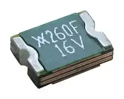
- PPTC Case Style:1812 (4532 Metric); Product Range:PolySwitch miniASMDC Series; Voltage Rating:16VDC; Holding Current:2.6A; Trip Current:5A; Time to Trip:5s; C 34AK1011
- Time to Trip: 5s
- Trip Current: 5A
- Product Range: PolySwitch miniASMDC Series
- Voltage Rating: 16VDC
- Holding Current: 2.6A
- PPTC Case Style: 1812 (4532 Metric)
- Current Rating Max: 100A
- Operating Temperature Max: 85°C
- Operating Temperature Min: -40°C
- Automotive Qualification Standard: AEC-Q200
| Delivery and price | |
|---|---|
| Units per pack | 250 |
| Price | 0.386 € |
| Current stock | 10+ |
| Lead time | 30 days |
PPTC **Datasheet**

## **Automotive miniASMDC Series** Surface Mount

**==> picture [87 x 14] intentionally omitted <==**

**----- Start of picture text -----**<br>
WHF_1®@ RoHS<br>**----- End of picture text -----**<br>


## **Description**

The miniASMDC is small-sized 1812 PPTC series, helping to reduce weight of wire harnesses. PPTC devices distributed in a circuit can allow the use of smaller wire sizes with the resulting harnesses. Forego looping back and forth around a fuse box and place your protection wherever you see fit. The solid state composition of PPTC devices helps provide reliability.

## **Features & Benefits**

## **Additional Information**

**==> picture [210 x 75] intentionally omitted <==**

**----- Start of picture text -----**<br>
Resources Accessories Samples<br>Agency Approvals<br>Agency Agency File Number<br> E74889<br>**----- End of picture text -----**<br>


- Products meet applicable ■ Surface-mount form factor automotive industry ■ High Performance standards

- Expertise from the world’s

- ■ Compatible with high-volume leading resettable overcurrent electronics assembly protection manufacturer

- Small footprint – 1812 size

- ■ Wide range of dedicated

- ■ Resettable solution against automotive surface-mount overcurrent and short-circuit and radial-leaded resettable

- ■ AEC-Q200 qualified, RoHS overcurrent devices compliant, and ■ High performance transient ISO/TS16949 certified voltage protection devices

## **Applications**

- High Performance

- Expertise from the world’s leading resettable overcurrent protection manufacturer

- Wide range of dedicated automotive surface-mount and radialleaded resettable overcurrent devices

- High performance transient voltage protection devices

© 2021 Littelfuse, Inc. Specifications are subject to change without notice. Revised: GD. 11/12/21

**1**

PPTC **Datasheet**

**Automotive miniASMDC Series** Surface Mount

**==> picture [46 x 52] intentionally omitted <==**

**==> picture [286 x 52] intentionally omitted <==**

## **Electrical Characteristics**

**==> picture [506 x 233] intentionally omitted <==**

**----- Start of picture text -----**<br>
Part   Ordering Part  IH(A)@ IH(A)@ IT VMAX IMAX PD Typ Max Time-to-trip RMIN RMAX R1MAX<br>Number Number (R1MAX) (RaMAX) (A) (VDC) (A) (W) (A) (s) (Ω) (Ω) (Ω)<br>miniASMDC – 12-60V<br>miniASMDC010F RF2151-000 0.10 0.10 0.30 60 40 0.75 0.50 5.00 0.70 12.70 12.70<br>miniASMDC014F RF2152-000 0.14 0.14 0.28 60 10 0.75 8.00 0.01 1.50 6.00 6.00<br>miniASMDC020F RF2153-000 0.20 0.20 0.40 30 10 0.80 8.00 0.02 0.60 3.30 3.30<br>miniASMDC030F RF2154-000 0.30 0.30 0.60 30 40 0.80 8.00 0.10 0.20 1.75 1.75<br>miniASMDC050F RF2155-000 0.50 0.50 1.00 24 100 0.80 8.00 0.15 0.15 1.00 1.00<br>miniASMDC075F RF4566-000 0.75 0.75 1.50 13.2 100 1.00 8.00 0.20 0.11 0.45 0.45<br>miniASMDC075F/24 RF2156-000 0.75 0.75 1.50 24 40 0.80 8.00 0.30 0.09 0.29 0.29<br>miniASMDC075F/33 RF4567-000 0.75 0.75 1.60 33 100 1.00 8.00 1.00 0.11 0.39 0.39<br>miniASMDC110F/16 RF2157-000 1.10 1.10 2.20 16 100 0.80 8.00 0.30 0.06 0.18 0.18<br>miniASMDC110F/24 RF2158-000 1.10 1.10 2.20 24 20 0.80 8.00 0.50 0.06 0.18 0.18<br>miniASMDC125F/16 RF2159-000 1.25 1.25 2.50 16 100 0.80 8.00 0.40 0.05 0.14 0.14<br>miniASMDC150F/12 RF4568-000 1.50 1.50 2.80 12 100 0.80 8.00 0.50 0.04 0.11 0.11<br>miniASMDC150F/16 RF2160-000 1.50 1.50 2.80 16 100 0.80 8.00 0.50 0.04 0.11 0.11<br>miniASMDC150F/24 RF2161-000 1.50 1.50 3.00 24 20 1.00 8.00 1.50 0.04 0.12 0.12<br>miniASMDC200F/16 RF4161-000 2.00 2.00 4.00 16 40 1.20 8.00 5.00 0.02 0.085 0.085<br>miniASMDC260F/12 RF4569-000 2.60 2.60 5.00 12 100 1.00 8.00 5.00 0.015 0.047 0.047<br>miniASMDC260F/13.2 RF4570-000 2.60 2.60 5.00 13.2 100 1.20 8.00 5.00 0.015 0.05 0.05<br>miniASMDC260F/16 RF2162-000 2.60 2.60 5.00 16 100 1.20 8.00 5.00 0.015 0.05 0.05<br>**----- End of picture text -----**<br>


## **Notes:**

- **IH :** Hold current: maximum current device will pass without interruption in 25°C, unless otherwise specified

**IT :** Trip current: minimum current that will switch the device from low-resistance to high-resistance in 25°C still air, unless otherwise specified.

- **VMAX :** Maximum voltage device can withstand without damage at rated current.

   - **PD :** Power dissipated from device when in the tripped state in 25°C still air, unless otherwise specified. **RMIN :** Minimum resistance of device as supplied at 25°C, unless otherwise specified.

   - **R1MAX :** Maximum resistance of device when measured one hour post reflow, unless otherwise specified. **RaMAX :** Maximum functional resistance of device after being subjected to the stresses described in PS400 at

   - 25°C, unless otherwise specified.

- **IMAX :** Maximum fault current device can withstand without damage at rated voltage.

## **Typical Time-to-Trip Curves at 25°C**

## **miniASMDC**

**==> picture [490 x 191] intentionally omitted <==**

**----- Start of picture text -----**<br>
100<br>A  =  miniASMDC010F, miniASMDC014F<br>B =  miniASMDC020F A B D F<br>C = D =  miniASMDC030FminiASMDC050F 10 C EG HI JLK M N O<br>E =  miniASMDC075F<br>F =  miniASMDC075F/24 1<br>G =  miniASMDC075F/33 O<br>H =  miniASMDC110F/16<br>0.1<br>I  =  miniASMDC110F/24<br>F<br>J =  miniASMDC125F/16 EG I N M<br>K =  miniASMDC150F/12 0.01 D HJ K<br>L =  miniASMDC150F/16 L<br>B<br>M =  miniASMDC150F/24<br>C<br>A<br>N =  miniASMDC200F/16 0.001<br>0.1 1 10 100<br>O =  miniASMDC260F/12, miniASMDC260F/13.2,<br>Fault Current (A)<br>miniASMDC260F/16<br>Time-to-Trip (s)<br>**----- End of picture text -----**<br>


**Note:** The average time current curves and Temperature Rerating curve performance is affected by a number or variables, and these curves provided as guidance only. Customer must verify the performance in their application.

© 2021 Littelfuse, Inc. Specifications are subject to change without notice. Revised: GD. 11/12/21

**2**

PPTC **Datasheet**

**Automotive miniASMDC Series** Surface Mount

**==> picture [46 x 52] intentionally omitted <==**

**==> picture [286 x 52] intentionally omitted <==**

## **Typical Time-to-Trip Curves at 25°C**

**==> picture [506 x 254] intentionally omitted <==**

**----- Start of picture text -----**<br>
Maximum Ambient Temperature<br>Part Number -40°C  -20°C  0°C  20°C  25°C 40°C 50°C 60°C 70°C 85°C<br>Hold Current (A)<br>miniASMDC – 12-60V<br>miniASMDC010F 0.17  0.15  0.13  0.11  0.10  0.09  0.08  0.07  0.06  0.04<br>miniASMDC014F 0.23  0.20  0.17  0.14  0.13  0.11  0.10  0.09  0.07  0.05<br>miniASMDC020F 0.30  0.27  0.23  0.20  0.19  0.17  0.15  0.13  0.12  0.09<br>miniASMDC030F 0.49  0.44  0.39  0.32  0.30  0.27  0.24  0.22  0.18  0.14<br>miniASMDC050F 0.59  0.57  0.55  0.50  0.48  0.45  0.43  0.35  0.30  0.23<br>miniASMDC075F 1.10  0.99  0.87  0.75  0.72  0.63  0.57  0.49  0.45  0.35<br>miniASMDC075F/24 1.50  1.25  1.00  0.75  0.73  0.65  0.60  0.55  0.50  0.43<br>miniASMDC075F/33 1.09  0.98  0.87  0.77  0.75  0.66  0.61  0.55  0.50  0.41<br>miniASMDC110F/16 1.68  1.49  1.30  1.10  1.05  0.92  0.83  0.75  0.64  0.50<br>miniASMDC110F/24 2.00  1.70  1.40  1.10  1.06  0.95  0.88  0.80  0.73  0.61<br>miniASMDC125F/16 2.00  1.69  1.47  1.25  1.17  1.03  0.92  0.90  0.69  0.53<br>miniASMDC150F/12 2.40  2.10  1.80  1.50  1.44  1.25  1.13  1.00  0.88  0.69<br>miniASMDC150F/16 2.40  2.10  1.80  1.50  1.44  1.25  1.13  1.00  0.88  0.69<br>miniASMDC150F/24 2.10  1.90  1.70  1.50  1.44  1.25  1.13  1.00  0.88  0.69<br>miniASMDC200F/16 3.07  2.74  2.40  2.07  2.00  1.74  1.57  1.40  1.24  0.99<br>miniASMDC260F/12 3.40  3.16  3.00  2.60  2.54  2.32  2.18  2.00  1.90  1.69<br>miniASMDC260F/13.2 3.40  3.16  3.00  2.60  2.54  2.32  2.18  2.00  1.90  1.69<br>miniASMDC260F/16 3.50  3.20  3.00  2.60  2.53  2.30  2.15  2.00  1.85  1.63<br>**----- End of picture text -----**<br>


## **Temperature Rerating Curve**

**==> picture [244 x 163] intentionally omitted <==**

**----- Start of picture text -----**<br>
200<br>150<br>100<br>50<br>0<br>-40  -20  0  20  40  60  80  100  120<br>Ambient Temperature (°C)<br>% of Rated Hold and Trip Current<br>**----- End of picture text -----**<br>


## **Physical Specifications**

|**Terminal Pad Material**|100% Matte Tin with Nickel Underplate|
|---|---|
|**Soldering Characteristics**|Solderability per ANSI-J-STD-002<br>Category3|
|**Solder Heat Withstand**|per IEC 60068-2-20, Test Tb, Section 5,<br>Method 1a|
|**Flammability**|per IEC 60695-11-5 Needle Flame<br>Test for 20 seconds|
|**Recommended Storage**<br>**Conditions**|40°C max, 70% RH max; Devices May<br>Not Meet Specifed Ratings if Storage<br>Conditions are Exceeded|
|**Operation Temperature**|-40°C to 85°C|
|**Note:**See PS400 for other physical specifcations.||


## **Environmental Specifications**

**==> picture [506 x 128] intentionally omitted <==**

**----- Start of picture text -----**<br>
Test Conditions Resistance Change<br>60°C, 1000 hrs ±3% Typical<br>Passive Aging  85°C, 1000 hrs ±5% Typical<br>Humidity Aging 85°C, 85% R.H., 100 hrs ±1.2% Typical<br>Thermal Shock 85°C, -40°C 20 times -33% Typical<br>Freon No change<br>Solvent Resistance Trichloroethane No change<br>Hydrocarbons No change<br>Note:  See PS400 for other environmental specifications.<br>Moisture Resistance Level Level 2a, J-STD-020<br>40°C max, 70% RH max; devices should remain in original sealed bags prior to use.<br>Storage Conditions<br>Devices may not meet specifed values if these storage conditions are exceeded.<br>**----- End of picture text -----**<br>


© 2021 Littelfuse, Inc. Specifications are subject to change without notice. Revised: GD. 11/12/21

**3**

PPTC **Datasheet**

**Automotive miniASMDC Series** Surface Mount

**==> picture [46 x 52] intentionally omitted <==**

**==> picture [286 x 52] intentionally omitted <==**

## **Dimension**

**==> picture [505 x 282] intentionally omitted <==**

**----- Start of picture text -----**<br>
Dimensions in Millimeters (Inches)<br>Part Number A B C D E Figure<br>Min Max Min Max Min Max Min Max Min Max<br>miniASMDC – 12-60V<br>miniASMDC010<br>miniASMDC014F 0.635  0.89<br>miniASMDC020F 4.73 (0.025) (0.035)<br>miniASMDC030F (0.186)<br>miniASMDC050F 0.38  0.62<br>miniASMDC075F (0.015) (0.025) A B<br>4.83 0.81<br>miniASMDC075F/24<br>(0.190) (0.032) 1.46<br>4.73 0.94 (0.057)<br>miniASMDC075F/33<br>(0.190) (0.037) C<br>0.28  0.48<br>miniASMDC110F/16<br>4.37  (0.011) (0.019) 3.07 3.41  0.25  0.95  0.20<br>1<br>(0.172) 0.81 1.46  (0.121) (0.134) (0.010) (0.040) (0.008) [—]<br>miniASMDC110F/24<br>(0.032) (0.057) D E<br>miniASMDC125F/16 4.83<br>(0.190) 0.28  0.48<br>miniASMDC150F/12<br>(0.011) (0.019)<br>miniASMDC150F/16<br>1.00 1.94<br>miniASMDC150F/24<br>(0.040) (0.077)<br>4.73 0.51 1.22<br>miniASMDC200F/16<br>(0.186) (0.020) (0.048)<br>miniASMDC260F/12<br>4.83 1.02 1.52<br>miniASMDC260F/13.2<br>(0.190) (0.042) (0.060)<br>miniASMDC260F/16<br>**----- End of picture text -----**<br>


## **Recommended Pad Layout**

**==> picture [504 x 309] intentionally omitted <==**

**----- Start of picture text -----**<br>
Recommended Pad Layout<br>A<br>B C B<br>Recommended Pad Layout Figures [mm (in)]<br>Part Tape and Reel   Standard   Part<br>Number Quantity Package Marking Dimension A  Dimension B  Dimension C<br>(Min*/Nom) (Nom) (Nom)<br>miniASMDC – 12-60V<br>miniASMDC010F 10<br>miniASMDC014F 14<br>miniASMDC020F 2<br>2,000 10,000<br>miniASMDC030F 3<br>miniASMDC050F 5<br>miniASMDC075F 7<br>miniASMDC075F/24 075F 24V<br>1,500 7,500<br>miniASMDC075F/33 075F 33V<br>miniASMDC110F/16 2,000 10,000 110F 16V 3.15 (0.124) 1.68 (0.066) 3.10 (0.122)<br>miniASMDC110F/24 1,500 7,500 110F 24V<br>miniASMDC125F/16 125F 16V<br>miniASMDC150F/12 2,000 10,000 150F 12V<br>miniASMDC150F/16 150 16V<br>miniASMDC150F/24 1,000 5,000 150F 24V<br>miniASMDC200F/16 2,000 10,000 200F 16V<br>miniASMDC260F/12 260F 12V<br>miniASMDC260F/13.2 1,500 7,500 260F 13V<br>miniASMDC260F/16 260F 16V<br>*  These devices are intended for use in automotive applications.<br>**----- End of picture text -----**<br>


© 2021 Littelfuse, Inc. Specifications are subject to change without notice. Revised: GD. 11/12/21

**4**

PPTC **Datasheet**

**Automotive miniASMDC Series** Surface Mount

**==> picture [46 x 52] intentionally omitted <==**

**==> picture [286 x 52] intentionally omitted <==**

## **Solder Reflow Recommendations**

|**Profle Feature**|**Pb-Free Assembly**|
|---|---|
|**Average ramp up rate (Ts to Tp)**|3°C/s max|
|**MAX**<br>**Preheat**|-|
|**•  Temperature min (TsMIN)**|150°C|
|**•  Temperature max (TsMAX)**|200°C|
|**•  Time (tsMIN to tsMAX)**|60-120 s|
|**Time maintained above:**||
|**•  Temperature (TL)**|217°C|
|**•  Time (tL)**|60-150 s|
|**Peak/Classifcation temperature (Tp)**|260°C|
|**Time within 5°C of actualpeak temperature**||
|**Time (tp)**|30 s max|
|**Ramp down rate**|3°C/s max|
|**Time 25°C topeak temperature**|8 min max|


**==> picture [244 x 163] intentionally omitted <==**

**----- Start of picture text -----**<br>
tp<br>Tp Critical Zone<br>Ramp Up TL to Tp<br>TL TsMAX tL<br>TsMIN<br>ts<br>Preheat Ramp Down<br>25<br>t 25˚C to Peak<br>Reflow Profile Time<br>Temperature<br>**----- End of picture text -----**<br>


**Note:** All temperatures refer to topside of the package, measured on the package body surface.

## **Solder Reflow**

- Recommended reflow method: IR, hot air, nitrogen.

- Recommended maximum paste thickness: 0.25mm (0.010in)

- Devices can be cleaned using standard methods and aqueous solvents.

- Experience has shown the optimum conditions for forming acceptable solder fillets occur when a reasonable amount of solder paste is placed underneath each device’s termination.  As such, we request that customers comply with our recommended solder pad layouts.

- Customer should validate that the solder paste amount and reflow recommendations meet its application.

- We request that customer board layouts refrain from placing raised features (e.g. vias, nomenclature, traces, etc.) underneath PolySwitch devices. It is possible that raised features could negatively impact solderability performance of our devices.

## **Rework**

- Standard industry practices. (Please also avoid direct contact to the device.)

## **Part Ordering Number System**

**==> picture [131 x 100] intentionally omitted <==**

**----- Start of picture text -----**<br>
miniASMDC      075      F     /24      -2<br>**----- End of picture text -----**<br>


**==> picture [99 x 65] intentionally omitted <==**

**----- Start of picture text -----**<br>
Packaging<br>2 = Tape and Reel<br>Alternative Voltage Rating (If Applicable)<br>Lead Free<br>Hold Current Indicator<br>Product Series<br>**----- End of picture text -----**<br>


© 2021 Littelfuse, Inc. Specifications are subject to change without notice. Revised: GD. 11/12/21

**5**

PPTC **Datasheet**

**Automotive miniASMDC Series** Surface Mount

**==> picture [46 x 52] intentionally omitted <==**

**==> picture [286 x 52] intentionally omitted <==**

## **Tape and Reel Specifications**

**==> picture [506 x 302] intentionally omitted <==**

**----- Start of picture text -----**<br>
miniASMDC EIA 481-1 (mm)<br>miniASMDC010F miniASMDC075F/24<br>miniASMDC110F/16<br>miniASMDC014F miniASMDC075F/33<br>miniASMDC125F/16<br>Description miniASMDC020F miniASMDC110F/24<br>miniASMDC150F/12 miniASMDC150F/24<br>miniASMDC030F miniASMDC260F/12<br>miniASMDC150F/16<br>miniASMDC050F miniASMDC260F/13.2<br>miniASMDC200F/16<br>miniASMDC075F miniASMDC260F/16<br>W 12.0 ± 0.30 12.0 ± 0.30 12.0 ± 0.30<br>P0 4.0 ± 0.10 4.0 ± 0.10 4.0 ± 0.10<br>P1 8.0 ± 0.10 8.0 ± 0.10 8.0 ± 0.10<br>P2 2.0 ± 0.05 2.0 ± 0.05 2.0 ± 0.05<br>A0 3.5 ± 0.1 3.7 ± 0.1 3.7 ± 0.1<br>B0 4.95 ± 0.1 4.9 ± 0.1 4.9 ± 0.1<br>B1 max 6.15 6.15 6.15<br>D0 1.5 + 0.10/ -.00 1.5 + 0.10/ -.00 1.5 + 0.10/ -.00<br>F 5.50 ± 0.05 5.50 ± 0.05 5.50 ± 0.05<br>E1 1.75 ± 0.10 1.75 ± 0.10 1.75 ± 0.10<br>E2 min 10.25 10.25 10.25<br>T max 0.35 0.35 0.35<br>T1 max 0.1 0.1 0.1<br>K0 0.9 ± 0.1 1.4 ± 0.1 1.78 ± 0.1<br>A max  185 185 185<br>N min 50 50 50<br>W1 12.4 + 2.0/-.00 12.4 + 2.0/-.00 12.4 + 2.0/-.00<br>W2 max 18.4 18.4 18.4<br>**----- End of picture text -----**<br>


© 2021 Littelfuse, Inc. Specifications are subject to change without notice. Revised: GD. 11/12/21

**6**

PPTC **Datasheet**

**Automotive miniASMDC Series** Surface Mount

**==> picture [46 x 52] intentionally omitted <==**

**==> picture [286 x 52] intentionally omitted <==**

## **Tape and Reel Diagrams**

**==> picture [432 x 268] intentionally omitted <==**

**----- Start of picture text -----**<br>
Embossment<br>P 0<br>T D0 P 2<br>E1<br>Cover Tape<br>A 0 F<br>W<br>E2<br>B1 K0 B0<br>T1 P 1<br>Center Lines<br>of Cavity<br>W2 (Measured at Hub)<br>A N (Hub Dia.)<br>Cover Tape<br>Carrier Tape W1 (Measured at Hub)<br>Embossed Cavity<br>**----- End of picture text -----**<br>


## **WARNING**

- Users should independently evaluate the suitability of and test each product selected for their own application.

- Operation beyond the maximum ratings or improper use may result in device damage and possible electrical arcing and flame.

- These devices are intended for protection against damage caused by occasional overcurrent or overtemperature fault conditions and should not be used when repeated fault conditions

- or prolonged trip events are anticipated.

- Contamination of the PPTC material with certain silicone-based oils or some aggressive solvents can adversely impact the performance of the devices.

- Device performance can be impacted negatively if devices are handled in a manner inconsistent with recommended electronic, thermal, and mechanical procedures for electronic

- components.

- PPTC devices are not recommended for installation in applications where the device is constrained such that its PTC properties are inhibited, for example in rigid potting materials or in

- rigid housings, which lack adequate clearance to accommodate device expansion.

- Operation in circuits with a large inductance can generate a circuit voltage (Ldi/dt) above the rated voltage of the device.

**Disclaimer Notice -** Information furnished is believed to be accurate and reliable. However, users should independently evaluate the suitability of and test each product selected for their own applications. Littelfuse products are not designed for, and may not be used in, all applications. Read complete Disclaimer Notice at www.littelfuse.com/disclaimer-electronics.

© 2021 Littelfuse, Inc. Specifications are subject to change without notice. Revised: GD. 11/12/21

**7**
Updated at April 12, 2026
Founded in 1927 and headquartered in Chicago, Illinois, Littelfuse is a premier global manufacturer of circuit protection, power control, and sensing technologies. Widely recognized for pioneering the first small, fast-acting protective fuse, the company has grown into an industry leader whose highly reliable components are essential to modern industrial, transportation, and consumer electronics applications worldwide. At the core of the Littelfuse portfolio is an expansive and industry-leading range of circuit protection solutions. This encompasses a massive selection of traditional fuses, fuse holders, and resettable PTC thermistor fuses designed to safely interrupt overcurrent conditions. To defend against electrical overstress, Littelfuse also provides advanced transient voltage suppression (TVS) technologies, including thousands of specialized TVS diodes, TVS varistors, and gas discharge tubes (GDTs) that ensure robust defense against voltage spikes and environmental hazards. Beyond its foundational protection components, Littelfuse manufactures a diverse array of discrete semiconductors, sensors, and switching devices. Engineers rely on their high-performance thyristors, including TRIACs and SCRs, alongside power-efficient Schottky diodes and MOSFETs for demanding power control applications. Complemented by precision proximity sensors and highly reliable reed and solid-state relays, Littelfuse delivers the critical building blocks required for secure, efficient, and complete system design.
About Novapart
Novapart is a B2B electronic component broker specialising in stock shortages and cost reduction. We source hard-to-find parts and identify compliant alternatives across a catalogue of 540,000+ components from 500+ manufacturers.
Learn more →Stock Shortage Specialist
When a component is unavailable, discontinued or has an unacceptable lead time, we tap into our network of vetted European and Asian distributors to source what you need — without compromising on quality or traceability.
Request a quote →Compliant Alternatives
We identify pin-to-pin, electrically equivalent substitutes that meet the same certifications (RoHS, AEC-Q100, REACH) as your original specification — validated against datasheets, not just part numbers. Often at a lower cost.
BOM Analysis service →