
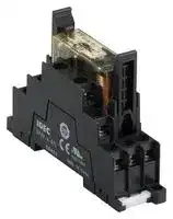


RF1V-3A1BLD1-D24
Safety Relay, w/Diode & LED Indicator, 24 VDC, 3PST-NO, SPST-NC, RF1V Series, Through Hole, 6 A
- Manufacturer: IDEC
- Product type: Safety Relays
- SVHC: No SVHC (25-Jun-2025)
- IP Rating: -
- Coil Voltage: 24VDC
- Product Range: RF1V Series
- Relay Mounting: Through Hole
- Contact Current: 6A
- Relay Terminals: PC Pin
- Contact Material: Silver Tin Oxide, Gold
- Contact Configuration: 3PST-NO, SPST-NC
- Contact Voltage AC Nom: 250V
- Contact Voltage DC Nom: 30V
| Delivery and price | |
|---|---|
| Units per pack | 20 |
| Price | 28.77 € |
| Current stock | 10+ |
| Lead time | 30 days |
## Force Guided Relays **==> picture [77 x 27] intentionally omitted <==** **----- Start of picture text -----**<br> RF Series<br>**----- End of picture text -----**<br> ## Force guided contact mechanism EN 61810-3 Type A TÜV approved ## Fast Response Time Response time of 8ms. Ensures safety by turning the load off quickly. ## High Shock Resistance High shock resistant suitable for use in machine tools and in environments subjected to vibration and shocks. (200m/s[2 ] minimum) ## Clear Visiblilty Available with a built-in LED. ## Output expansion for safety relay modules and safety controllers ## HR6S Safety Relay Module Cost effective and easy method to expand mechanical contact outputs. Enables flexible construction of safety circuits Compact and EN compliant RF1V force guided relays. **==> picture [197 x 142] intentionally omitted <==** **----- Start of picture text -----**<br> • Circuit Example<br>Interlock Switch/ Start<br>Emergency Stop Switch Switch F1 F2<br>Safety Relay Module<br>| EDM Input Safety Output Expansion<br>K2 Force Guided Relays<br>K1 Force Guided Relays<br>EDM input: External device monitor input<br>**----- End of picture text -----**<br> (RF1V force guided relays) Interlock Switch/ Start Emergency Stop Switch Switch F1 F2 (RF2 force guided relays) Safety Relay Module MEO • See website for details on approvals and standards. ~~C~~ Ew ~~|~~ EDM Input ## FS1B Safety Controller Solid state safety outputs of safety controllers can be converted to mechanical contact outputs. **==> picture [213 x 206] intentionally omitted <==** **----- Start of picture text -----**<br> No. of Poles Page<br>6-pole E-186<br>7<br>4-pole E-186<br>2-pole E-192<br>Se<br>**----- End of picture text -----**<br> **==> picture [188 x 125] intentionally omitted <==** **----- Start of picture text -----**<br> • Circuit Example<br>Interlock Switch/ Start<br>Emergency Stop Switch Switch<br>Safety Controller 24V<br>EDM Input Safety Output Expansion<br>K2 Force Guided Relays<br>K1 Force Guided Relays<br>o e |<br>**----- End of picture text -----**<br> E-185 RF1V / SF1V Force-guided Relays Relay Sockets es ## Compact and EN compliant RF1V force guided relays. APEM Switches & Pilot Lights Control Boxes Emergency Stop Switches Enabling Switches Safety Products Explosion Proof Terminal Blocks **==> picture [139 x 99] intentionally omitted <==** **----- Start of picture text -----**<br> With SF1V<br>PC board mount socket<br>4-pole 6-pole<br>With SF1V<br>DIN rail mount socket<br>**----- End of picture text -----**<br> Relays & Sockets |||||||||||||||||Relays & Sockets| |---|---|---|---|---|---|---|---|---|---|---|---|---|---|---|---|---| |||||||||||||||Quantity: 10||Relays & Sockets| |||||Contact||Rated Coil Voltage||Without LED Indicator|||With LED Indicator||With Counter-electromotive Force Diode<br>With LED Indicator|||Circuit<br>Protectors| |||||||||Part No.|||Part No.||Part No.|||Power Supplies| |||||||12V DC||RF1V-2A2B-D12|||RF1V-2A2BL-D12||RF1V-2A2BLD1-D12|||| ||||||2NO-2NC<br>24V DC|||RF1V-2A2B-D24|||RF1V-2A2BL-D24||RF1V-2A2BLD1-D24|||LED Illumination| ||4-pole|||||48V DC<br>12V DC||RF1V-2A2B-D48<br>RF1V-3A1B-D12|||RF1V-2A2BL-D48<br>RF1V-3A1BL-D12||RF1V-2A2BLD1-D48<br>RF1V-3A1BLD1-D12|||Controllers| ||||||3NO-1NC<br>24V DC|||RF1V-3A1B-D24|||RF1V-3A1BL-D24||RF1V-3A1BLD1-D24|||Operator<br>Interfaces| |||||||48V DC||RF1V-3A1B-D48|||RF1V-3A1BL-D48||RF1V-3A1BLD1-D48|||Interfaces| ||6-pole<br>4NO-2NC<br>12V DC<br>RF1V-4A2B-D12<br>RF1V-4A2BL-D12<br>RF1V-4A2BLD1-D12<br>24V DC<br>RF1V-4A2B-D24<br>RF1V-4A2BL-D24<br>RF1V-4A2BLD1-D24<br>48V DC<br>RF1V-4A2B-D48<br>RF1V-4A2BL-D48<br>RF1V-4A2BLD1-D48<br>5NO-1NC<br>12V DC<br>RF1V-5A1B-D12<br>RF1V-5A1BL-D12<br>RF1V-5A1BLD1-D12<br>24V DC<br>RF1V-5A1B-D24<br>RF1V-5A1BL-D24<br>RF1V-5A1BLD1-D24<br>48V DC<br>RF1V-5A1B-D48<br>RF1V-5A1BL-D48<br>RF1V-5A1BLD1-D48<br>3NO-3NC<br>12V DC<br>RF1V-3A3B-D12<br>RF1V-3A3BL-D12<br>RF1V-3A3BLD1-D12<br>24V DC<br>RF1V-3A3B-D24<br>RF1V-3A3BL-D24<br>RF1V-3A3BLD1-D24<br>48V DC<br>RF1V-3A3B-D48<br>RF1V-3A3BL-D48<br>RF1V-3A3BLD1-D48<br>~~ESS~~|||||||||||||||Sensors<br>AUTO-ID<br>Interlock<br>Switches<br>Non-contact<br>Interlock Switches| |Sockets||||||||Quantity: 10||||||||Safety Laser<br>Scanners<br>Safety Light| |||||||||||||||||Safety Light| ||||||Types|No. of Poles||Part No.||||||||Curtains| |||||||||||||||||| ||DIN Rail Mount Sockets|DIN Rail Mount Sockets||||4<br>6||SF1V-4-07L<br>SF1V-6-07L||||||||Safety Modules| ||PC Board Mount Sockets||PC Board Mount Sockets|||4<br>6||SF1V-4-61<br>SF1V-6-61||||||||| |Coil Ratings||||||||||||||||FS1B| ||Contact<br>Rated Coil<br>Voltage (V)<br>Rated Current (mA)<br>±10%<br>(at 20°C) (Note 1)<br>Coil<br>Resistance (Ω)<br>±10% (at 20°C)<br>OperatingCharacteristics(at 20°C)<br>Power<br>Consumption<br>Pickup Voltage<br>(initial value)<br>Dropout Voltage<br>(initial value)<br>Maximum allowable<br>Voltage(Note 2)<br>~~a~~|||||||||||||||RF1V<br>RF2| ||4-pole<br>2NO-2NC<br>12V DC<br>30.0<br>400<br>24V DC<br>15.0<br>1,600<br>48V DC<br>7.5<br>6,400<br>3NO-1NC<br>12V DC<br>30.0<br>400<br>24V DC<br>15.0<br>1,600<br>48V DC<br>7.5<br>6,400<br>~~===s~~|||||||||||||Approx. 0.36W||HR2S<br>HR1S| |||||||12V DC<br>41.7<br>288||||||||||| ||||||4NO-2NC|24V DC<br>20.8<br>1,152|||||75% maximum|10% minimum<br>110%||||| |||||||48V DC<br>10.4<br>4,608||||||||||| |||||||12V DC<br>41.7<br>288||||||||||| ||6-pole||||5NO-1NC|24V DC<br>20.8<br>1,152||||||||Approx. 0.50W||| |||||||48V DC<br>10.4<br>4,608||||||||||| |||||||12V DC<br>41.7<br>288||||||||||| ||||||3NO-3NC|24V DC<br>20.8<br>1,152||||||||||| |||||||48V DC<br>10.4<br>4,608||||||||||| Circuit Protectors Power Supplies LED Illumination Controllers Operator Interfaces Sensors AUTO-ID Interlock Switches Non-contact Interlock Switches Safety Laser Scanners Safety Light Curtains Safety Modules Note 1: For relays with LED indicator, the rated current increases by approx. 2mA. Note 2: Maximum allowable voltage is the maximum voltage that can be applied to relay coils. E-186 RF1V Force Guided Relays / SF1V Relay Sockets ## Relay Specifications **==> picture [549 x 409] intentionally omitted <==** **----- Start of picture text -----**<br> Number of Poles 4-pole 6-pole<br>Contact Configuration 2NO-2NC 3NO-1NC 4NO-2NC 5NO-1NC 3NO-3NC<br>Contact Resistance (initial value) (Note 1) 100 mΩ maximum<br>Contact Material AgSnO [2] (Au flashed)<br>Rated Load (resistive load) 6A 250V AC, 6A 30V DC<br>Allowable Switching Power (resistive load) 1500 VA, 180W DC (30V DC max.), 85W DC (30V to 120V DC max.)<br>Allowable Switching Voltage 250V AC, 125V DC<br>APEM Allowable Switching Current 6A<br>Minimum Applicable Load (Note 2) 5V DC, 1 mA (reference value)<br>Switches &<br>Pilot Lights Power Consumption (approx.) 0.36W 0.50W<br>Insulation Resistance 1000 MΩ minimum (500V DC megger, same measurement positions as the dielectric strength)<br>Control Boxes Between contact and coil 4000V AC, 1 minute<br>Emergency 2500V AC, 1 minute<br>Stop Switches 2500V AC, 1 minute Between contacts 7-8 and 11-12<br>Enabling Between contacts 7-8 and 9-10 Between contacts 9-10 and 13-14<br>Switches Between contacts 11-12 and 13-14<br>Dielectric<br>Between contacts of different poles 4000V AC, 1 minute<br>Safety Products Strength 4000V AC, 1 minute Between contacts 3-4 and 5-6<br>Between contacts 3-4 and 5-6<br>Between contacts 3-4 and 7-8<br>Explosion Proof Between contacts 3-4 and 7-8 Between contacts 5-6 and 9-10<br>Between contacts 5-6 and 9-10<br>Between contacts 7-8 and 9-10<br>Terminal Blocks<br>Between contacts of the same pole 1500V AC, 1 minute<br>Operate Time (at 20°C) 20 ms maximum (at the rated coil voltage, excluding contact bounce time)<br>Relays & Sockets<br>Response Time (at 20°C) (Note 3) 8 ms maximum (at the rated coil voltage, excluding contact bounce time, without diode) (Note 4)<br>Circuit Release Time (at 20°C) 20 ms maximum (at the rated coil voltage, excluding contact bounce time, without diode)<br>Protectors<br>Vibration Operating Extremes 10 to 55 Hz, amplitude 0.75 mm<br>Power Supplies Resistance Damage Limits 10 to 55 Hz, amplitude 0.75 mm<br>Shock Operating Extremes (half sine-wave pulse: 11 ms) 200 m/s [2] , when mounted on DIN rail mount socket: 150 m/s [2]<br>LED Illumination<br>Resistance Damage Limits (half sine-wave pulse: 6 ms) 1000 m/s [2]<br>Controllers 250V AC 6A resistive load: 100,000 operations minimum (operating frequency 1200 per hour)<br>30V DC 6A resistive load: 100,000 operations minimum (operating frequency 1200 per hour)<br>Operator 250V AC 1A resistive load: 500,000 operations minimum (operating frequency 1800 per hour)<br>Interfaces Electrical Life 30V DC 1A resistive load: 500,000 operations minimum (operating frequency 1800 per hour)<br>[AC 15] 240V AC 2A inductive load: 100,000 operations minimum<br>Sensors (operating frequency 1200 per hour, cos ø = 0.3)<br>[DC 13] 24V DC 1A inductive load: 100,000 operations minimum<br>AUTO-ID (operating frequency 1200 per hour, L/R = 48 ms)<br>Mechanical Life 10 million operations minimum (operating frequency 10,800 operations per hour)<br>Operating Temperature (Note 5) –40 to +85°C (no freezing)<br>Operating Humidity 5 to 85%RH (no condensation)<br>Interlock Storage Temperature –40 to +85°C (no freezing)<br>Switches Storage Humidity 5 to 85%RH (no condensation)<br>Non-contact Operating Frequency (rated load) 1200 operations per hour<br>Interlock Switches<br>Weight (approx.) 20g 23g<br>**----- End of picture text -----**<br> Interlock Switches Non-contact Interlock Switches Safety Laser Scanners Safety Light Curtains Safety Modules Note 1: Measured using 6V DC,1A voltage drop method. Note 2: Failure rate level P (reference value) Note 3: Response time is the time until NO contact opens, after the coil voltage is turned off. Note 4: With diode: 12ms maximum (at the rated coil voltage, excluding contact bounce time) Note 5: See the table below for the current and operating temperature ## Socket Specifications ## Operating Temperature (relay, socket) **==> picture [549 x 226] intentionally omitted <==** **----- Start of picture text -----**<br> Model SF1V-4-07L SF1V-6-07L SF1V-4-61 SF1V-6-61<br>Single mounting Collective mounting<br>Rated Current 6A<br>FS1B Rated VoltaInsulation Resistancege 250V AC/DC1000 MΩ minimum (500V DC megger, between terminals) Operating Temperature –40˚C to +85˚C 4-pole6-pole –40˚C to +70˚C–40˚C to +65˚C<br>RF1V Applicable Wire 0.7 to 1.65 mm(18 AWG to 14 AWG [2] ) — Contact<br>6A 6A<br>RF2 Recommended Screw Tightening Torque 0.5 to 0.8 N·m — Current When the ambient<br>HR2S Screw Terminal Style M3 slotted Phillips self-tapping screw — When the ambient 4-pole temperature is over 60°C, lower the contact current at<br>HR1S Terminal Strength Wire tensile strength: 50N min. — temperature is over 70°C, lower the contact current 0.1A/°C.<br>Dielectric Strength 2500V AC, 1 minute(Between live and dead metal parts, between live parts of different poles) at 0.1A/°C.5NO1NC: When the ambient temperature is over 50°C,<br>Vibration Resistance Damage limits: 10 to 55 Hz, amplitude 0.75 mmResonance: 10 to 55 Hz, amplitude 0.75 mm Remarks Up to 70°C: Keep the total current of NO side to 24A lower the contact current at 0.1A/°C.<br>Shock Resistance 1000 m/s [2] maximum. 6-pole 5NO1NC:<br>Over 70°C: Lower the Up to 50°C: Keep the total<br>Operating Temperature (Note) –40 to +85°C (no freezing) contact current at 0.1A/°C. current of NO side to 24A maximum.<br>Operating Humidity 5 to 85% RH (no condensation) Over 50°C: Lower the contact<br>Storage Temperature –40 to +85°C (no freezing) current at 0.1A/°C.<br>Storage Humidity 5 to 85% RH (no condensation)<br>Degree of Protection IP20(finger-safe screw terminals) — Applicable Crimping Terminal All dimensions in mm.<br>Weight (approx.) 40g 55g 9g 10g<br>6.3 max. 3.0 min.<br>**----- End of picture text -----**<br> 4.0 max. 6.5 min. Note: Ring tongue terminals cannot be used. Note: See the table at right for the current and operating temperature. E-187 RF1V Force Guided Relays / SF1V Relay Sockets ## Accessories **==> picture [494 x 278] intentionally omitted <==** **----- Start of picture text -----**<br> Item Shape Specifications Part No. Quantity Remarks<br>Aluminum Length: 1m<br>DIN Rail BAA1000 10<br>Weight: Approx. 200g Width: 35 mm<br>[ai| | |<br>19<br>BNL5 10<br>45 9<br>Metal (zinc plated steel) —<br>End Clip<br>Weight: Approx. 15g<br>24<br>l ea BNL6 10<br>7 45 , 9<br>Characteristics Notes on Contact Gaps except Welded Contacts<br>Maximum Switching Capacity Electrical Life Curve Example: RF1V-2A2B-D24 1 3 4 7 8<br>Contact<br>Current 500 +<br>–<br>AC 2 5 6 9 10<br>resistive load 100<br>106 • If the NO contact (7-8 or 9-10) welds, the NC contact (3-4 or 5-6)<br>remains open even when the relay coil is de-energized, maintaining a<br>DCresistive load 30V DC resistive load gap of 0.5 mm minimum. The remaining unwelded NO contact (9-10 or<br>1 10 250V AC resistive load 7-8) is either open or closed.<br>• If the NC contact (3-4 or 5-6) welds, the NO contact (7-8 or 9-10)<br>remains open even when the relay coil is energized, maintaining a gap<br>0.11 aitiiamaniitat 10 125 250 it ee 1 i 0.1 1 10 of 0.5 mm minimum. The remaining unwelded NC contact (5-6 or 3-4) is either open or closed.<br>Contact Voltage (V) Contact Current (A)<br>Life (× 10,000 operations)<br>**----- End of picture text -----**<br> **==> picture [494 x 434] intentionally omitted <==** **----- Start of picture text -----**<br> LC Dimensions (All dimensions in mm.)<br>RF1V Relays PC Board Terminal Model<br>Mounting Hole Layout (Bottom View)<br>RF1V (4-pole) RF1V (6-pole)<br>50 max. RF1V (4-pole)<br>40 max.<br>13 max. 13 max.<br>(1.83) 5.08 [±0.1]<br>13.97 ±0.1 11.43 ±0.1<br>5.08<br>RF1V (6-pole)<br>1.0 1.83 0.5 1.0 1.83 0.5<br>10.16 13.97 5.08 10.16 13.97 5.08<br>5.08 11.43 5.08 5.08 5.08 (1.83) 5.08 ±0.1<br>11.43 13.97 ±0.1 5.08 ±0.1<br>5.08 ±0.1 5.08 ±0.1<br>11.43 [±0.1]<br>NE<br>Internal Connection (Bottom View)<br>RF1V (4-pole) RF1V (6-pole)<br>Without LED Indicator Without LED Indicator<br>1 3 4 7 8 1 3 4 7 8 1 3 4 7 8 11 12 1 3 4 7 8 11 12 1 3 4 7 8 11 12<br>+ + + + +<br>– – – – –<br>2 5 6 9 10 2 5 6 9 10 2 5 6 9 10 13 14 2 5 6 9 10 13 14 2 5 6 9 10 13 14<br>3NO-1NC Contact 2NO-2NC Contact 5NO-1NC Contact 4NO-2NC Contact 3NO-3NC Contact<br>With LED Indicator With LED Indicator<br>1 3 4 7 8 1 3 4 7 8 1 3 4 7 8 11 12 1 3 4 7 8 11 12 1 3 4 7 8 11 12<br>+ + + + +<br>– – – – –<br>2 5 6 9 10 2 5 6 9 10 2 5 6 9 10 13 14 2 5 6 9 10 13 14 2 5 6 9 10 13 14<br>3NO-1NC Contact 2NO-2NC Contact 5NO-1NC Contact 4NO-2NC Contact 3NO-3NC Contact<br>With Counter-electromotive Force Diode With Counter-electromotive Force Diode<br>1 3 4 7 8 1 3 4 7 8 1 3 4 7 8 11 12 1 3 4 7 8 11 12 1 3 4 7 8 11 12<br>+ + + + +<br>– – – – –<br>2 5 6 9 10 2 5 6 9 10 2 5 6 9 10 13 14 2 5 6 9 10 13 14 2 5 6 9 10 13 14<br>3NO-1NC Contact 2NO-2NC Contact 5NO-1NC Contact 4NO-2NC Contact 3NO-3NC Contact<br>10- ø1.4 holes<br>14- ø1.4 holes<br>±0.1<br>10.16<br>24 max. 24 max.<br>3.5 3.5<br>±0.1<br>10.16<br>**----- End of picture text -----**<br> APEM Switches & Pilot Lights Control Boxes Emergency Stop Switches Enabling Switches Safety Products Explosion Proof Terminal Blocks Relays & Sockets Circuit Protectors Power Supplies LED Illumination Controllers Operator Interfaces Sensors AUTO-ID Interlock Switches Non-contact Interlock Switches Safety Laser Scanners Safety Light Curtains Safety Modules FS1B RF1V RF2 HR2S HR1S E-188 RF1V Force Guided Relays / SF1V Relay Sockets (All dimensions in mm.) APEM Switches & Pilot Lights Control Boxes Emergency Stop Switches Enabling Switches Safety Products Operator Interfaces Sensors AUTO-ID Interlock Switches Non-contact Interlock Switches Safety Laser Scanners Safety Light Curtains Safety Modules ## Dimensions ## SF1V PC Board Mount Sockets Explosion Proof Terminal Blocks Relays & Sockets Circuit Protectors Power Supplies LED Illumination Controllers SF1V (4-pole) **==> picture [176 x 149] intentionally omitted <==** **----- Start of picture text -----**<br> 50 max.<br>(13)<br>(13) 0.8<br>6.93 0.4 10.16<br>13.97 5.08<br>5.08 11.43<br>15 max.<br>40 max.<br>6.2<br>3.6<br>3.5<br>0.6<br>**----- End of picture text -----**<br> PC Board Mounting Hole Layout / Terminal Arrangement (Bottom View) 3-ø3.2 holes for M3 self-tapping screws **==> picture [218 x 82] intentionally omitted <==** **----- Start of picture text -----**<br> 39.9 [±0.1]<br>4.1 [±0.1] 24.8 [±0.1]<br>1 3 4 7 8<br>2 5 6 9 10<br>(6.93) 5.08 [±0.1]<br>13.97 [±0.1] 11.43 [±0.1]<br>5.08 [±0.1]<br>10- ø1.1 hole<br> ±0.1<br>10.16<br>**----- End of picture text -----**<br> **==> picture [240 x 289] intentionally omitted <==** **----- Start of picture text -----**<br> SF1V (6-pole))<br>60 max.<br>(13) (13) 0.8<br>6.93 0.4 10.16<br>13.97 5.08<br>5.08 5.08<br>5.08<br>11.43<br>PC Board Mounting Hole Layout / Terminal Arrangement<br>(Bottom View)<br>3-ø3.2 holes for M3 self-tapping screws<br>49.9±0.1<br>4.1±0.1 24.8±0.1<br>1 3 4 7 8 11 12<br>2 5 6 9 10 13 14<br>(6.93) 5.08<br>13.97±0.1 5.08 ±0.1<br>5.08 ±0.1 5.08 ±0.1<br>11.43±0.1<br>14-ø1.1 hole<br>15 max.<br>6.2 40 max.<br>3.6<br>3.5<br>0.6<br>±0.1<br>10.16<br>**----- End of picture text -----**<br> ## SF1V (6-pole)) PC Board Mounting Hole Layout / Terminal Arrangement (Bottom View) ## SF1V DIN Rail Mount Socket Dimensions FS1B RF1V RF2 HR2S HR1S ## SF1V (4-pole) **==> picture [205 x 263] intentionally omitted <==** **----- Start of picture text -----**<br> 4<br>(Internal Connection)<br>M3 Terminal<br>10 7 8 Screws<br>9<br>6<br>5<br>4<br>3 2 1<br>(Top View) R2<br>6.3<br>22.4<br>35.4<br>ø6.2<br>62.4 58.9<br>5.3<br>4<br>6.5<br>5<br>75<br>6.5<br>**----- End of picture text -----**<br> ## (Panel Mounting Hole Layout) **==> picture [192 x 62] intentionally omitted <==** **----- Start of picture text -----**<br> 80.0 ±0.2 2–M3.5 or ø4 holes<br>(Top View)<br>±0.2<br>14.5<br>**----- End of picture text -----**<br> ## SF1V (6-pole) **==> picture [220 x 357] intentionally omitted <==** **----- Start of picture text -----**<br> 4<br>(Internal Connection)<br>14 12 M3 Terminal<br>Screws<br>13 11<br>10 8<br>9 7<br>ø6.2<br>6 4<br>5 2 1 3<br>(Top View)<br>R2<br>6.3<br>29.8<br>35.4<br>(Panel Mounting Hole Layout)<br>80.0 [±0.2] 2–M3.5 or ø4 holes<br>(Top View)<br>5 6.5<br>75<br>6.5<br>62.4 58.9<br>5.3<br>4<br>±0.2<br>22<br>**----- End of picture text -----**<br> E-189 RF1V Force Guided Relays / SF1V Relay Sockets Switches & Pilot Lights Control Boxes Emergency Stop Switches Enabling Switches LED Illumination Controllers Operator Interfaces Sensors AUTO-ID Interlock Switches Non-contact Interlock Switches Safety Laser Scanners Safety Light Curtains Safety Modules ## Operating Instructions ## 1. Driving Circuit for Relays 1. To make sure of correct relay operation, apply rated voltage to the relay coil. Pickup and dropout voltages may differ according to operating temperature and conditions. 2. Input voltage for DC coil: - A complete DC voltage is best for the coil power to make sure of stable operation. When using a power supply containing a ripple voltage, suppress the ripple factor within 5%. When power is supplied through a rectifications circuit, relay operating characteristics, such as pickup voltage and dropout voltage, depend on the ripple factor. Connect a smoothing capacitor for better operating characteristics as shown below. **==> picture [108 x 115] intentionally omitted <==** **----- Start of picture text -----**<br> Smoothing<br>Capacitor<br>+<br>– R Relay<br>Pulsation<br>Emin Emax Emean DC<br>Emax – Emin<br>Ripple Factor (%) Emean × 100%<br>Emax = Maximum of pulsating current<br>Emin = Minimum of pulsating current<br>Emean = DC mean value<br>**----- End of picture text -----**<br> 5. Surge suppression for transistor driving circuits: When the relay coil is turned off, a high-voltage pulse is generated. Be sure to connect a diode to suppress the counter electromotive force, or use RF1V with counter-electromotive force diode. Then, the coil release time becomes slightly longer. To shorten the coil release time, connect a Zener diode between the collector and emitter of the controlling transistor. Select a Zener diode with a Zener voltage slightly higher than the power voltage. **==> picture [81 x 46] intentionally omitted <==** **----- Start of picture text -----**<br> Counter emf<br>suppressing diode<br>+<br>– R Relay<br>**----- End of picture text -----**<br> 6. The coil terminal of the relay has polarity. Connect terminals according to the internal connection diagram. Incorrect wiring may cause malfunction. ## 2. Protection for Relay Contacts 1. The contact ratings show maximum values. Make sure that these values are not exceeded even momentarily. When an inrush current flows through the load, the contact may become welded. If this is the case, connect a contact protection circuit, such as a current limiting resistor. APEM Safety Products Explosion Proof Terminal Blocks Relays & Sockets Circuit Protectors Power Supplies 2. Contact protection circuit: 3. Operating the relay in sync with an AC load: **==> picture [106 x 77] intentionally omitted <==** **----- Start of picture text -----**<br> TE<br>R<br>Load<br>EAC<br>Vin<br>EAC<br>Vin<br>**----- End of picture text -----**<br> If the relay operates in sync with AC power voltage of the load, the relay life may be reduced. If this is the case, select a relay in consideration of the required reliability for the load. Or, make the relay turn on and off irrespective of the AC power phase or near the point where the AC phase crosses zero voltage. 4. Leakage current while relay is off: Incorrect **==> picture [104 x 110] intentionally omitted <==** **----- Start of picture text -----**<br> R TE<br>I0<br>Correct<br>R<br>**----- End of picture text -----**<br> When driving an element at the same time as the relay operation, special consideration is needed for the circuit design. As shown in the incorrect circuit below, leakage current (Io) flows through the relay coil while the relay is off. Leakage current causes coil release failure or adversely affects the vibration resistance and shock resistance. Design a circuit as shown in the correct example. - When switching an inductive load, arcing causes carbides to form on the contacts, resulting in an increased contact resistance. In consideration of contact reliability, contact life, and noise suppression, use of a surge absorbing circuit is recommended. Note that the release time of the load becomes slightly longer. Check the operation using an actual load. Incorrect use of a contact protection circuit will adversely affect switching characteristics. Four typical examples of contact protection circuits are shown in the following table: |RC|Power<br>C<br>R<br>Ind. Load|This protection circuit can be used when the load<br>impedance is smaller than the RC impedance in<br>an AC load power circuit.<br>R: Resistor of approximately the same resistance<br>value as the load<br>C: 0.1 to 1μF|| |---|---|---|---| ||C<br>R<br>Power<br>Ind. Load|This protection circuit can be used for both AC<br>and DC load power circuits.<br>R: Resistor of approximately the same resistance<br>value as the load<br>C: 0.1 to 1μF|| |Diode|+<br>–<br>D<br>Power<br>Ind. Load|This protection circuit can be used for DC load<br>power circuits. Use a diode with the following<br>ratings.<br>Reverse withstand voltage:<br>Power voltage of the load circuit × 10<br>Forward current:<br>More than the load current|| |Varistor|Varistor<br>Power<br>Ind. Load|This protection circuit can be used for both AC<br>and DC load power circuits.<br>For a best result, when using on a power voltage<br>of 24 to 48V AC/DC, connect a varistor across<br>the load. When using on a power voltage of 100<br>to 240V AC/DC, connect a varistor across the<br>contacts.|| E-190 RF1V Force Guided Relays / SF1V Relay Sockets APEM Switches & Pilot Lights Control Boxes Emergency Stop Switches Enabling Switches Safety Products Circuit Protectors Power Supplies LED Illumination Controllers Operator Interfaces Sensors AUTO-ID Interlock Switches Non-contact Interlock Switches Safety Laser Scanners Safety Light Curtains Safety Modules FS1B RF1V RF2 HR2S HR1S ## Operating Instructions Explosion Proof Terminal Blocks Relays & Sockets 3. Do not use a contact protection circuit as shown below: ||Power<br>C<br>Load<br>This protection circuit is very effective in arc suppression<br>when opening the contacts. But, the capacitor is charged<br>while the contacts are opened. When the contacts are<br>closed, the capacitor is discharged through the contacts,<br>increasingthepossibilityof contact welding.| |---|---| ||C<br>Load<br>Power<br>This protection circuit is very effective in arc suppression<br>when opening the contacts. But, when the contacts are<br>closed, a current fows to charge the capacitor, causing<br>contact welding.| Generally, switching a DC inductive load is more difficult than switching a DC resistive load. Using an appropriate arc suppressor will improve the switching characteristics of a DC inductive load. ## 3. Usage, transport, and storage conditions 1. Temperature, humidity, atmospheric pressure during usage, transport, and storage. - Temperature: –40°C to +85°C (no freezing) See E-187 for the current and operating temperature. - Humidity: 5 to 85%RH (no condensation) The humidity range varies with temperature. Use within the range indicated in the chart below. - Atmospheric pressure: 86 to 106 kPa - Operating temperature and humidity range **==> picture [130 x 104] intentionally omitted <==** **----- Start of picture text -----**<br> Humidity (%RH)<br>85<br>Tolerance Range<br>(Avoid freezing (Avoid<br>when using at condensation<br>temperatures when using at<br>below 0ºC) temperatures<br>above 0ºC)<br>5<br>–40 0 85<br>Temperature (ºC)<br>**----- End of picture text -----**<br> ## 2. Condensation - Condensation occurs when there is a sudden change in temperature under high temperature and high humidity conditions. The relay insulation may deteriorate due to condensation. 3. Freezing Condensation or other moisture may freeze on the relay when the temperatures is lower than 0ºC. This causes problems such as sticking of movable parts or delay in operation. 4. Low temperature, low humidity environments Plastic parts may become brittle when used in low temperature and low humidity environments. ## 4. Panel Mounting When mounting DIN rail mount sockets on a panel, take the following into consideration. - Use M3.5 screws, spring washers, and hex nuts. - For mounting hole layout, see dimensions on E-189. - Keep the tightening torque within 0.49 to 0.68 N·m. Excessive tightening may cause damage to the socket. ## 5. Others 1. General notice - To maintain the initial characteristics, do not drop or shock the relay. - The relay cover cannot be removed from the base during normal operation. To maintain the initial characteristics, do not remove the relay cover. - Use the relay in environments free from condensation, dust, sulfur dioxide (SO2), and hydrogen sulfide (H2S). - The RF1V relay cannot be washed as it is not a sealed type. Also make sure that flux does not leak to the PC board and enter the relay. 2. Connecting outputs to electronic circuits: - When the output is connected to a load which responds very quickly, such as an electronic circuit, contact bouncing causes incorrect operation of the load. Take the following measures into consideration. - Connect an integration circuit. - Suppress the pulse voltage due to bouncing within the noise margin of the load. 3. Do not use relays in the vicinity of strong magnetic field, as this may affect relay operation. 4. UL and CSA ratings may differ from product rated values determined by IDEC. ## 6. Notes on PC Board Mounting - When mounting 2 or more relays on a PC board, keep a minimum spacing of 10 mm in each direction. If used without spacing of 10 mm, rated current and operating temperature differs. Consult IDEC. - Manual soldering: Solder the terminals at 400°C within 3 sec. - Auto-soldering: Preliminary heating at 120°C within 120 sec. Solder at 260°C±5°C within 6 sec. - Because the terminal part is filled with epoxy resin, do not excessively solder or bend the terminal. Otherwise, air tightness will degrade. - Avoid the soldering iron from touching the relay cover or the epoxy filled terminal part. - Use a non-corrosive resin flux. E-191 RF2 / SJ Series Socket 2-pole Force Guided Relay Interlock Switches Non-contact Interlock Switches Safety Laser Scanners Safety Light Curtains Safety Modules ## For simple and easy safety measure. Reduce cost and installation space. APEM **==> picture [181 x 98] intentionally omitted <==** **----- Start of picture text -----**<br> PC board terminal<br>é<br>* = Ci<br>Plug-in terminal SJ series relay socket<br>**----- End of picture text -----**<br> ## Force Guided Relays |Contact Configuration<br>~~ee~~|Contact Configuration<br>~~ee~~|Terminal<br>Style<br>~~ee~~|LED Indicator<br>~~ae~~<br>~~a~~|w/diode<br>of reverse<br>polaritycoil<br>~~ae~~<br>~~es~~|Degree of Protection<br>~~eses~~|Degree of Protection<br>~~eses~~|Rated<br>Coil Voltage<br>~~es~~|Part No.| |---|---|---|---|---|---|---|---|---| ||||||Flux-tight (RTII)<br>~~es~~<br>~~es~~|Sealed (RTIII)<br>~~es~~||| |2-pole<br>~~ee~~|SPST-NO +<br>SPST-NC<br>~~ee~~|Plug-in<br>~~ee ~~<br>~~———————~~<br>~~———————~~|With<br> ~~ae ~~<br>~~a~~<br>~~———————~~|√<br> ~~ae ~~<br>~~es~~<br>~~———————~~|√<br> ~~es ~~<br>~~es~~<br>~~———————~~|—<br> ~~es~~<br>~~———————~~|12V DC<br>~~es~~|RF2S-1A1BLD1-D12<br>~~ee~~| ||||Without<br>~~a~~<br>~~———————~~<br>~~———————~~|—<br>~~es ~~<br>~~———————~~<br>~~ee~~|√<br> ~~es~~<br>~~———————~~<br>~~ee~~|—<br>~~———————~~<br>~~ee~~|24V DC<br>~~ee~~|RF2S-1A1B-D24<br>~~ee~~<br>~~|~~| |||||√<br>~~———————~~<br>~~ee~~<br>~~———————~~|√<br>~~———————~~<br>~~ee~~<br>~~———————~~|—<br>~~———————~~<br>~~ee~~<br>~~———————~~||RF2S-1A1BD1-D24<br>~~ee~~<br>~~|~~<br>~~|~~| ||||With<br>~~———————~~<br>~~———————~~<br>~~Ee~~<br>~~ee~~|√<br>~~———————~~<br>~~ee ~~<br>~~———————~~<br>~~ee~~|√<br>~~———————~~<br> ~~ee~~<br>~~———————~~<br>~~ee~~|—<br>~~———————~~<br>~~ee~~<br>~~———————~~||RF2S-1A1BLD1-D24<br>~~ee~~<br>~~|~~<br>~~|~~<br>~~|~~| |||||√<br>~~———————~~<br>~~ee~~<br>~~e~~~~**s**~~<br>|—<br>~~———————~~<br>~~ee~~<br>~~**ee**~~|√<br>~~———————~~||RF2S-1A1BLD1K-D24<br>~~|~~<br>~~|~~<br>~~Co~~| ||||Without<br>~~———————~~<br>~~Ee~~<br>~~ee~~|—<br>~~———————~~<br>~~ee~~<br>~~e~~~~**s**~~<br>~~e~~|√<br>~~———————~~<br>~~ee~~<br>~~**ee**~~|—<br>~~———————~~<br>~~ee~~|48V DC<br>~~ee~~|RF2S-1A1B-D48<br>~~|~~<br>~~|~~<br>~~Co~~<br>~~-~~| ||||With<br>~~Ee~~<br>~~ee~~<br>~~ee~~<br>~~ee~~|√<br>~~ee ~~<br>~~e~~~~**s**~~<br>~~e~~<br>~~ee~~|√<br> ~~ee~~<br>~~**ee**~~<br>~~ee~~|—<br>~~ee~~||RF2S-1A1BLD1-D48<br>~~|~~<br>~~Co~~<br>~~-~~<br>~~oo~~| |||||√<br>~~e~~~~**s**~~<br>~~e~~<br>~~ee~~<br>~~ee~~<br>|—<br>~~**ee**~~<br>~~ee~~|√<br>~~ee~~||RF2S-1A1BLD1K-D48<br>~~Co~~<br>~~-~~<br>~~oo~~<br>~~ee~~| ||DPDT (*1)||Without<br>~~ee ~~<br>~~ee~~<br>~~ee~~<br>~~a~~|—<br>~~e~~~~**s** ~~<br> ~~e~~<br>~~ee~~<br>~~ee~~<br>~~ee~~|√<br> ~~**ee**~~<br>~~ee~~|—<br>~~ee~~|24V DC<br>~~ee ~~<br>~~es~~|RF2S-2C-D24<br>~~Co~~<br> ~~-~~<br>~~oo~~<br>~~ee~~<br>~~ee~~| ||||Without<br>~~ee~~<br>~~ee~~<br>~~a~~<br>~~ee~~|√<br>~~ee~~<br>~~ee~~<br>~~ee~~<br>~~**e**e~~|√<br>~~ee~~|—||RF2S-2CD1-D24<br>~~oo~~<br>~~ee~~<br>~~ee~~<br>~~**e**ee~~| ||||With<br>~~ee ~~<br>~~a~~<br>~~ee~~|√<br>~~ee~~<br> ~~ee~~<br>~~**e**e~~<br>~~s~~|√|—||RF2S-2CLD1-D24<br>~~ee~~<br>~~ee~~<br>~~**e**ee~~<br>~~e~~| ||||With<br> <br>~~a~~<br>~~ee~~|√<br> ~~ee~~<br>~~**e**e~~<br>~~s~~<br>~~a~~|—<br>~~es ee~~|√<br>~~ee~~||RF2S-2CLD1K-D24<br>~~ee~~<br>~~**e**ee~~<br>~~e~~| ||SPST-NO +<br>SPST-NC<br>~~|~~|PC Board|Without<br>~~ee~~<br>~~ee~~<br>~~Rs~~|—<br>~~**e**e~~<br>~~s~~<br>~~a~~<br>~~ee~~|√<br>~~es ee~~<br>~~es~~|—<br>~~ee~~|12V DC<br>~~es~~|RF2V-1A1B-D12<br>~~**e**ee~~<br>~~e~~<br>~~Co~~| |||||—<br>~~a~~<br>~~ee~~<br>~~ee~~|√<br>~~es ee~~<br>~~es~~<br>~~ee~~|—<br>~~ee~~<br>~~ee~~|24V DC<br>~~es~~<br>~~ee~~<br>~~ee~~|RF2V-1A1B-D24<br>~~Co~~<br>~~a~~| |||||—<br>~~ee~~<br>~~ee~~<br>~~ee~~|—<br>~~es~~<br>~~ee~~<br>~~ee~~|√<br>~~ee~~<br>~~ee~~||RF2V-1A1BK-D24<br>~~Co~~<br>~~a~~<br>~~eee~~| |||||√<br>~~ee ~~<br>~~ee~~<br>~~ee~~|√<br> ~~ee~~<br>~~ee~~<br>~~ee~~|—<br>~~ee~~<br>~~ee~~||RF2V-1A1BD1-D24<br>~~a~~<br>~~eee~~<br>~~|~~| |||||√<br>~~ee~~<br>~~ee~~<br>~~es~~|—<br>~~ee~~<br>~~ee~~|√<br>~~ee~~||RF2V-1A1BD1K-D24<br>~~eee~~<br>~~|~~<br>~~ee~~| ||||With<br>~~ee~~<br>~~Rs~~|√<br>~~ee~~<br>~~es~~<br>~~es~~|—<br>~~ee~~<br>~~es~~|√<br>~~es~~||RF2V-1A1BLD1K-D24<br>~~|~~<br>~~ee~~| ||||Without<br>~~ee~~<br>~~Rs~~<br>~~Rs~~|—<br>~~ee ~~<br>~~es~~<br>~~es~~<br>~~es~~|√<br> ~~ee~~<br>~~es~~|—<br>~~es~~|48V DC|RF2V-1A1B-D48<br>~~|~~<br>~~ee~~| ||DPDT(*1)<br>~~|~~||Without<br>~~Rs~~<br>~~Rs~~|—<br>~~es~~<br>~~es ~~<br>~~es~~|√<br> ~~es~~|—<br>~~es~~|24V DC|RF2V-2C-D24<br>~~ee~~| Switches & Pilot Lights Control Boxes Emergency Stop Switches Enabling Switches Safety Products Explosion Proof Terminal Blocks Relays & Sockets Circuit Protectors Power Supplies LED Illumination Controllers Operator Interfaces Sensors AUTO-ID FS1A - *1) When using DPDT model as a force guided relay, use in SPST-NO+SPST-NC wiring (EN50205). - Other part numbers are available. See below (contact IDEC for details). ## Part No. Development RF 2 S – 1A1B LD1 K – D24 ~~es Gd QO QO~~ Series No. of Poles Terminal Style Contact Configuration Option Degree of Rated Coil Voltage Protection 2 2-pole S Plug-in 1A1B SPST-NO + SPST-NC Blank Standard Blank RTII D12 12V DC ~~i ee~~ V PC Board ~~eeee~~ 2C DPDT ~~ee~~ DL With LED indicatorWith diode (Note 1) K RTIII ~~-7.~~ D24 24V DC ~~ee ee ee eeePp~~ D48 48V DC With diode of reverse polarity coil D1 (Note 2) Note 1: With diode: terminal 1 –, terminal 8 + LD With LED indicator & diode (Note 1) Note 2: With diode of reverse polarity coil: terminal 1 +, terminal 8 – Note 3: Use this chart for interpreting part numbers. Not all possible LD1 With LED indicator & diode of variations can be realized. ~~Pf~~ reverse polarity coil (Note 2) RF1V RF2 HR2S HR1S E-192 RF2 2-pole Force Guided Relay / SJ Series Socket APEM Switches & Pilot Lights Control Boxes Emergency Stop Switches Enabling Switches Safety Products Explosion Proof Terminal Blocks ## Standard Ratings |Standard|Ratings|Ratings||||||| |---|---|---|---|---|---|---|---|---| |Voltage|UL RatingResistive<br>NO<br>NC||CSA RatingResistive|||Voltage|TÜV RatingResistive|| |||NC|NO|NC|||NO|NC| |277V AC|6A|3A|6A|3A||240VAC|6A|3A| |30V DC|6A|3A|6A|3A||24V DC|6A|3A| ## Ratings ## Coil ratings |Rated Voltage<br>(V)|<br>Rated Current (mA)<br>±15%(at 20°C)|<br>Rated Current (mA)<br>±15%(at 20°C)|Coil Resistance<br>±10% (at 20°C)|OperatingCharacteristics(against rated values at 20°C)|OperatingCharacteristics(against rated values at 20°C)|OperatingCharacteristics(against rated values at 20°C)|Power<br>Consumption| |---|---|---|---|---|---|---|---| |||||Minimum Pickup<br>Voltage|Dropout Voltage|Maximum Allowable<br>Voltage (Note)|| ||Without LED|With LED|||||| |12V DC|58|63|205|75% maximum|10% minimum|110%|Approx. 0.7W| |24V DC|29|33|820||||| |48V DC|14.6|18|3300||||| Note: Maximum allowable voltage is the maximum voltage that can be applied to relay coils. ## Specifications |Explosion Proof|Specifications|Specifications||| |---|---|---|---|---| |Terminal Blocks<br>Relays & Sockets<br>Circuit<br>Protectors<br>Power Supplies<br>LED Illumination<br>Controllers<br>Operator<br>Interfaces<br>Sensors<br>AUTO-ID<br>Interlock<br>Switches<br>Non-contact<br>Interlock Switches<br>Safety Laser<br>Scanners<br>Safety Light<br>Curtains<br>Safety Modules<br>FS1B<br>RF1V<br>RF2<br>HR2S<br>HR1S|Model||RF2S (Plug-in Terminal)|RF2V (PC board terminal)| ||No. of Poles||2-pole|| ||Contact Confguration||SPST-NO + SPST-NC,DPDT|| ||DisconnectingMeans||Micro disconnection|| ||Contact Resistance(Note 1)||100mΩ maximum|| ||Contact Material||AgNi+Au-Clad|| ||Degree of Protection||RTII(fux-tight),RTIII(sealed)|| ||Rated Load (resistive load)||NO contact: 240V AC, 6A/24V DC, 6A<br>NC contact: 240V AC,3A/24V DC,3A|| ||Contact|Maximum Allowable Power<br>(resistive load)|NO contact: 1440VA/144W, NC contact: 720VA/72W|| |||Maximum Allowable Voltage|250V AC,125V DC|| |||Maximum Allowable Current|6A|| ||Minimum Applicable Load(Note 2)||1V DC,1mA|| ||Power Consumption||Approx. 0.7W|| ||Rated Insulation Voltage||250V|| ||Insulation Resistance||1000MΩ minimum(500V megger)|| ||Impulse Withstand Voltage||6000V|| ||Pollution Degree||2|| ||Dielectric<br>Strength|Between contact and coil|5000V AC,1 minute|| |||Between contacts of the samepole|4000V AC,1 minute|| |||Between contacts of the differentpoles|1500V AC,1 minute|| ||OperatingTime||15ms max.(at the rated coil voltage,excludingcontact bounce time)|| ||Response Time (Note 3)||5ms max. (at the rated coil voltage, without diode)<br>20ms max.(at the rated coil voltage,with diode)|| ||Release Time||10ms max. (at the rated coil voltage, excluding contact bounce time, without diode)<br>25ms max.(at the rated coil voltage,excludingcontact bounce time,with diode)|| ||Vibration<br>Resistance|Operating Extremes|NO contact: 10 to 55Hz, amplitude 0.75mm<br>NC contact:10 to 55Hz,amplitude 0.2mm|| |||Damage Limits|10 to 55Hz,amplitude 0.75mm|| ||Shock<br>Resistance|OperatingExtremes|NO contact: 100m/s2,NC contact: 50m/s2|| |||Damage Limits|1000m/s2|| ||Electrical Life||NO contact:<br>100,000 operations minimum (operating frequency 1,800 per hour) at 240V 6A resistive load or<br>2A inductive load (power factor 0.4)<br>100,000 operations minimum (operating frequency 1,800 per hour) at 24V 6A resistive load or<br>1A inductive load (time constant 48ms)<br>NC contact:<br>100,000 operations minimum (operating frequency 1,800 per hour) at 240V AC, 3A resistive load or 2A inductive<br>load (power factor 0.4)<br>100,000 operations minimum (operating frequency 1,800 per hour) at 24V DC, 3A resistive load or 1A inductive<br>load(time constant 48ms)|| ||Mechanical Life||10 million operations minimum(operatingfrequency18,000 operationsper hour)|| ||Operating Temperature||Single mounting: –40 to +70°C (no freezing)<br>Collective mounting: –40 to +55°C(no freezing)|–40 to +70°C (no freezing)| ||OperatingHumidity||5 to 85%RH(no condensation)|| ||Storage Temperature||–40 to +85°C(no freezing)|| ||Weight(approx.)||18g (without LED/diode),20g (with LED/with diode/with LED & diode)|| • Above values are initial values. Note 1: Measured using 5V DC, 1A voltage drop method. Note 2: Failure rate level P, reference value Note 3: Response time is the time until NO contact opens, after the coil voltage is turned off. E-193 RF2 2-pole Force Guided Relay / SJ Series Socket ## SJ Series Relay Socket **==> picture [152 x 84] intentionally omitted <==** **----- Start of picture text -----**<br> Removable<br>marking plate<br>Push-in terminal<br>*1) Release lever is supplied with the socket.<br>**----- End of picture text -----**<br> ( Fingersafe screw terminal) ( Standard screw terminal and Push-in terminal) • See website for details on approvals and standards. Note: Sockets can be used on RF2S (Plug-in terminal) only. APEM **==> picture [260 x 90] intentionally omitted <==** **----- Start of picture text -----**<br> Sockets<br>Terminal Style Part No. Quantity<br>Standard Screw Terminal SJ2S-05BS 1<br>DIN-rail Socket<br>Fingersafe Screw Terminal SJ2S-07L 1<br>(*1)<br>Push-in Terminal SJ2S-21L 1<br>PC Board Socket SJ2S-61 10<br>[SS<br>**----- End of picture text -----**<br> Switches & Pilot Lights Control Boxes Emergency Stop Switches Enabling Switches Safety Products Explosion Proof Terminal Blocks Relays & Sockets Circuit Protectors Power Supplies LED Illumination Controllers Operator Interfaces Sensors AUTO-ID - See website for details on PC board socket. ## Accessories and Replacement Parts (for DIN-rail Socket) **==> picture [549 x 531] intentionally omitted <==** **----- Start of picture text -----**<br> es Description/Shape Applicable Socket ee Part No. Material Part No. Quantity Remarks Terminal Blocks<br>Removable Marking Plate Marking area 15.2<br>Relays & Sockets<br>SJ2S-07L SJ9Z-PW<br>Plastic (white) Circuit<br>Protectors<br> -E] SJ2S-21L SJ9Z-P2100W (*3) Power Supplies<br>brass with Terminal centers: 15.8mm<br>For 8 sockets SJ2S-05BS SJ9Z-JF8S<br>A polypropylene coating Rated current: 12A LED Illumination<br>i For 2 sockets TL. SJ9Z-JF2<br>Jumper For 5 sockets Nickel-coated brass with SJ9Z-JF5 10 Terminal centers: 15.5mm Controllers<br>(*2) For 8 sockets SJ2S-07L polypropylene coating SJ9Z-JF8 Rated current: 12A<br>For 10 sockets SJ9Z-JF10 Operator<br>Interfaces<br>Zinc-plated steel with polybutylene A2 terminal of the coil is connected.<br>For 2 sockets SJ2S-21L SU9Z-J2102A<br>a=a res terephthalate coating Be The rated current is 2A. Sensors<br>Release Lever<br>AUTO-ID<br>SJ2S-05BS SJ9Z-CS −<br>Me Release Lever eit A part of the release lever can be cut off with nippers, etc. and<br>( with integrated marking plate) used as a marking plate. Interlock Switches<br>SJ2S-07L Plastic SJ9Z-CM 5 Non-contact<br>Marking area Interlock Switches<br>Safety Laser<br>12.2 Scanners<br>we<br>Release Lever Safety Light<br>Curtains<br>SJ2S-21L SJ9Z-C21R 10 − Safety Modules<br>2 eee i<br>*2) Ensure that the total current to the jumper does not exceed the maximum current. *3) Used for Push-in terminals.<br>Socket Specifications Applicable Crimping FS1B<br>es Model Rs SJ2S-05BS, SJ2S-07L (DIN Rail Socket) (PC Board SocketSJ2S-61 ) (Push-in Terminal SocketSJ2S-21L ) Terminal RF1V<br>Rated Current 8A ø3.2 min.<br>Rated Insulation Voltage 250V AC/DC 300V AC/DC (*5) | RF2<br>Solid wire / stranded wire: 5.9 max.<br>0.14 to 1.5mm [2] , AWG26 to 16<br>Applicable Wire 2mm [2] − Stranded wire with ferrule (without insulated cover):0.5 to 1.5mm [2] , AWG20 to 16 4.0 max. 5.3 min. HR2S<br>Stranded wire with ferrule (with insulated cover): HR1S<br>0.14 to 1.0mm [2] , AWG26 to 18<br>| Applicable Cripming Terminal See the dimensions shown at right − | −<br>Recommended Tightening Torque SJ2S-05BS: 0.6 to 1.0N∙mSJ2S-07L: 1.0N∙m − −<br>Screw Terminal Style M3 slotted Phillips screw (self-lifting) − −<br>Terminal Strength Wire tensile strength: 50N minimum − −<br>4.0 max. 5.3 to 6.5<br>ee Dielectric Strength (*4) Between contacts of the same Between contacts of the different Between contact and coil polepole 1000V AC3000V AC4000V AC,,, 1 min. 1 min. 1 min. 5000V AC, 1 min. 2500V AC, 1min.(between live and dead metal parts, between live metal parts of the different poles) Note: Ring terminal cannot be used on SJ2S-07L.<br>Vibration Resistance DamaResonancege limits Frequency 10 to 55Hz, amplitude 1.5mm 90m/sFrequency 10 to 55Hz, amplitude 0.75mm [2] 10 to 55Hz, amplitude 1.5mm See Cat. No. EP1728 for applicable terminals on Push-in terminals.<br>0 Shock Resistance (damage limits) ee A 100G (when using release lever) 1000m/s eee [2] 50G (when using release lever)<br>Operating Temperature −40 to +70°C (no freezing)<br>Operating Humidity 5 to 85% RH (no condensation)<br>Storate Temperature −55 to +85°C (no freezing) –40 to +70°C (no freezing)<br>——— Degree of Protection (Screw Terminal) SJ2S-07L: IP20 (IEC 60529) − −<br>Weight SJ2S-05BS: 30g, SJ2S-07L: 34g 4.5g 43g<br>8.6<br>6<br>5.9 max. 3.2 min.<br>**----- End of picture text -----**<br> - *4) The above are same when used with a RF2 force guided relay. *5) When using the socket with RF2S Force Guided Relay, the rated insulation voltage is 150V AC/DC. E-194 RF2 2-pole Force Guided Relay / SJ Series Socket ## Dimensions (All dimensions in mm.) ## Relay Dimensions PC Board Terminal Mounting Hole Layout (Bottom View) RF2S (plug-in terminal) Standard (without LED/diode) RF2V (PC board terminal) Standard (without LED/diode) **==> picture [104 x 188] intentionally omitted <==** **----- Start of picture text -----**<br> RF2V (SPST-NO + SPST-NC)<br>(1.6)<br>5 5<br>20<br>(28)<br>RF2V (DPDT)<br>(1.6)<br>5 5<br>20<br>(28)<br>6-ø1.3 holes<br>8-ø1.3 holes<br>(2.6) 7.5 (12.7)<br>(2.6) 7.5 (12.7)<br>**----- End of picture text -----**<br> **==> picture [337 x 144] intentionally omitted <==** **----- Start of picture text -----**<br> APEM<br>Switches &<br>Pilot Lights<br>Control Boxes 0.6 0.6 1.1<br>2.4 0.5 2 0.6<br>Emergency 0.5 0.6 12.7<br>Stop Switches 0.5 28<br>Enabling<br>Switches 20<br>5 5<br>Safety Products<br>Explosion Proof 5 5<br>19.4<br>Terminal Blocks 28<br>25.4<br>0.3 *25.4<br>0.3<br>6<br>4<br>8.9 8.1 12.7<br>7.5 7.5<br>**----- End of picture text -----**<br> - [ With LED/diode: 28.4] Relays & Sockets Circuit Protectors Power Supplies LED Illumination ## Socket Dimensions SJ2S-07L SJ2S-05BS M3 terminal screw **==> picture [199 x 168] intentionally omitted <==** **----- Start of picture text -----**<br> M3 terminal screw<br>4.3 71 ø3<br>11.2<br>8 (A2) 5 7 (21) 6<br>(24) (22) 6<br>1 (14) 4 (12) 2 3 12.2<br>(A1) (11)<br>Release lever<br>(TOP VIEW) marking plate dimensions<br>15.5 6<br>55.7<br>49.5<br>29.7<br>2<br>6<br>0.9 1.5<br>**----- End of picture text -----**<br> **==> picture [164 x 156] intentionally omitted <==** **----- Start of picture text -----**<br> 3.1 Max.70.2<br>8 7(22) (24) 5 6<br>(A2) (21)<br>(A1) (11)<br>1 2(12) (14)4 3<br>(TOP VIEW)<br>15.8<br>Max.55<br>Max.30<br>**----- End of picture text -----**<br> Controllers Operator Interfaces Sensors AUTO-ID Interlock Switches Non-contact Interlock Switches Safety Laser Scanners Safety Light Curtains Safety Modules ## SJ2S-61 SJ9Z-CS (Release Lever) ## SJ2S-21L **==> picture [190 x 119] intentionally omitted <==** **----- Start of picture text -----**<br> 32.5<br>25.8<br>0.3 1.0<br>15.3<br>14.0<br>36.5 38.5<br>1.0<br>4.0<br>**----- End of picture text -----**<br> **==> picture [5 x 7] intentionally omitted <==** **----- Start of picture text -----**<br> 16<br>**----- End of picture text -----**<br> FS1B RF1V RF2 HR2S HR1S **==> picture [135 x 135] intentionally omitted <==** **----- Start of picture text -----**<br> 102<br>(8) (7) (5) (6)<br>A2 22 24 21<br>Jumper Port (1) (2) (4) (3)<br>A1 12 14 11<br>(TOP VIEW)<br>63<br>43<br>**----- End of picture text -----**<br> ## SJ9Z-CM (Release Lever) ## SJ9Z-C21R (Release Lever) **==> picture [194 x 122] intentionally omitted <==** **----- Start of picture text -----**<br> • When the marking plate is not used<br>on the release lever.<br>28.1 24<br>15.3 16<br>38.5 41<br>**----- End of picture text -----**<br> E-195 RF2 2-pole Force Guided Relay / SJ Series Socket ## Dimensions **==> picture [488 x 382] intentionally omitted <==** **----- Start of picture text -----**<br> (All dimensions in mm.)<br>Internal Connection (Bottom View)<br>RF2*-1A1B- RF2*-1A1BLD1- RF2*-1A1BLD-<br>Standard With LED indicator + diode of reverse polarity coil With LED indicator + diode<br>1 1 1<br>(+) (–)<br>3 4 3 4 3 4<br>(−) (+)<br>8 7 6 8 7 6 7 6<br>RF2*-2C- RF2*-2CLD1- RF2*-2CLD-<br>Standard With LED indicator + diode of reverse polarity coil With LED indicator + diode<br>1 1 1<br>(+) (−)<br>2 3 4 2 3 4 2 3 4<br>(−) (+)<br>8 7 6 5 8 7 6 5 8 7 6 5<br>RF2*-1A1BL- RF2*-1A1BD1- RF2*-1A1BD-<br>With LED indicator With diode of reverse polarity coil With diode<br>1 1 1<br>(+) (–)<br>3 4 3 4 3 4<br>(−) (+)<br>8 7 6 8 7 6 8 7 6<br>RF2*-2CL- RF2*-2CD1- RF2*-2CD-<br>With LED indicator With diode of reverse polarity coil With diode<br>1 1 1<br>(+) (–)<br>2 3 4 2 3 4 2 3 4<br>(–) (+)<br>8 7 6 5 8 7 6 5 8 7 6 5<br>8<br>**----- End of picture text -----**<br> - Relays with diode have polarity. Take polarity into consideration when wiring. - When using DPDT model as a force guided relay, use in SPST-NO + SPST-NC wiring (EN50205). APEM Switches & Pilot Lights Control Boxes Emergency Stop Switches Enabling Switches Safety Products Explosion Proof Terminal Blocks Relays & Sockets Circuit Protectors Power Supplies LED Illumination Controllers Operator Interfaces Sensors AUTO-ID Interlock Switches Non-contact Interlock Switches Safety Laser Scanners Safety Light Curtains Safety Modules FS1B RF1V RF2 HR2S HR1S E-196 RF2 2-pole Force Guided Relay / SJ Series Socket APEM Switches & Pilot Lights Control Boxes Emergency Stop Switches Enabling Switches Safety Products Explosion Proof Terminal Blocks Relays & Sockets Operator Interfaces Sensors AUTO-ID Interlock Switches Non-contact Interlock Switches Safety Laser Scanners Safety Light Curtains Safety Modules FS1B RF1V ## Operating Instructions Circuit Protectors Power Supplies LED Illumination Controllers ## 1. When using DPDT model as a force guided relay Use in SPST-NO + SPST-NC wiring according to EN50205 (2002) RF2*-2C- Standard **==> picture [112 x 51] intentionally omitted <==** **----- Start of picture text -----**<br> 1<br>2 3 4<br>8 7 6 5<br>**----- End of picture text -----**<br> Example: Use terminal 3-4 as NO contact and 6-7 as NC contact. Or terminal 2-3 as NC contact and terminal 5-6 as NO contact. ## 2. Driving Circuit for Relays 2-1. To make sure of correct relay operation, apply rated voltage to the relay coil. Pickup and dropout voltages may differ according to operating temperature and conditions. 2-2. Input voltage for DC coil: A complete DC voltage is best for the coil power to make sure of stable operation. When using a power supply containing a ripple voltage, suppress the ripple factor within 5%. When power is supplied through a rectification circuit, the relay operating characteristics, such as pickup voltage and dropout voltage, depend on the ripple factor. Connect a smoothing capacitor for better operating characteristics as shown below. **==> picture [112 x 119] intentionally omitted <==** **----- Start of picture text -----**<br> Smoothing<br>Capacitor<br>+<br>–V R Relay<br>Pulsation<br>Emin Emax Emean DC<br>Emax−Emin<br>Ripple Fctor (%) Emean ×100%<br>Emax = Maximum pulsating current<br>Emin = Minimum of pulsating current<br>Emean = DC mean value<br>**----- End of picture text -----**<br> ## 2-4. Leakage current while relay is OFF When driving an element at the same time as the relay operation, special consideration is needed for the circuit design. As shown in the incorrect circuit at right, leakage current (Io) flows through the relay coil while the relay is off. Leakage current causes coil release failure or adversely affects the vibration resistance and shock resistance. Design a circuit as shown in the correct example. ## Correct **==> picture [110 x 100] intentionally omitted <==** **----- Start of picture text -----**<br> R TE<br>lo<br>Incorrect<br>R<br>**----- End of picture text -----**<br> ## 2-5. Surge suppression for transistor driving circuits: When the relay coil is turned off, a high-voltage pulse is generated. Be sure to connect a diode to suppress the counter electromotive force. Then, the coil release time becomes slightly longer. To shorten the coil release time, connect a Zener diode between the collector and emitter of the controlling transistor. Select a Zener diode with a Zener voltage slightly higher than the power voltage. **==> picture [90 x 41] intentionally omitted <==** **----- Start of picture text -----**<br> Counter emf +<br>suppressingdiode − R Relay<br>**----- End of picture text -----**<br> 2-6. The coil terminal of the relay has polarity. Connect terminals according to the internal connection diagram. Incorrect wiring may cause malfunction. ## 2-3. Operating the relay in sync with an AC load: **==> picture [105 x 80] intentionally omitted <==** **----- Start of picture text -----**<br> TE<br>R<br>Load<br>EAC<br>Vin<br>EAC<br>Vin<br>**----- End of picture text -----**<br> RF2 If the relay operates in sync with AC power voltage of the load, the relay life may be reduced. If this is the case, select a relay in HR2S consideration of the required reliability for the load. Or, make the relay HR1S turn on and off irrespective of the AC power phase or near the point where the AC phase crosses zero voltage. E-197 RF2 2-pole Force Guided Relay / SJ Series Socket ## Operating Instructions ## 3. Protection for Relay Contacts 3-1. The contact ratings show maximum values. Make sure that these values are not exceeded. When an inrush current flows through the load, the contact may become welded. If this is the case, connect a contact protection circuit, such as a current limiting resistor. 3-2. Contact protection circuit: When switching an inductive load, arcing causes carbides to form on the contacts, resulting in an increased contact resistance. In consideration of contact reliability, contact life, and noise suppression, use of a surge absorbing circuit is recommended. Note that the release time of the load becomes slightly longer. Check the operation using an actual load. Incorrect use of a contact protection circuit will adversely affect switching characteristics. Four typical examples of contact protection circuits are shown in the following table: |RC|Ind. Load<br>Power<br>C<br>R|This protection circuit can be used for both AC and<br>DC load power circuits.<br>R: Resistor of approximately the same resistance<br>value as the load.<br>C: 0.1 to 1μF| |---|---|---| |Diode|+<br>–<br>D<br>Ind. Load<br>Power|This protection circuit can be used for DC load power<br>circuits. Use a diode with the following ratings.<br>Reverse withstand voltage:<br>Power voltage of the load circuit × 10<br>Forward current:<br>More than the load current| |Varistor|Ind. Load<br>Power<br>Varistor|This protection circuit can be used for both AC and<br>DC load powercircuits. For the best result, when<br>using on a power voltage of 24 to 48V AC/DC,<br>connect a varistor across the load. When using on<br>a power voltage of 100 to 240V AC/DC, connect a<br>varistor across the contacts.| |3-3. Do not use a contactprotection circuit as shown below:||| |C<br>Load<br>Power<br>This protection circuit is very effective in arc suppression<br>when opening the contacts. But, when the contacts are closed,<br>a current fows to charge the capacitor, causing contact<br>welding.||| Generally, switching a DC inductive load is more difficult than switching a DC resistive load. Using an appropriate arc suppressor will improve the switching characteristics of a DC inductive load. ## 4. Usage, transport, and storage conditions 4-1. Condensation Condensation occurs when there is a sudden change in temperature under high temperature and high humidity conditions. The relay insulation may deteriorate due to condensation. - 4-2. Freezing Condensation or other moisture may freeze on the relay when the temperatures is lower than 0ºC. This causes problems such as sticking of movable parts or delay in operation. - 4-3. Low temperature, low humidity environments Plastic parts may become brittle when used in low temperature and low humidity environments. 5-2. Connecting outputs to electronic circuits: When the output is connected to a load which responds very quickly, such as an electronic circuit, contact bouncing causes incorrect operation of the load. Take the following measures into consideration. - Connect an integration circuit. - Suppress the pulse voltage due to bouncing within the noise margin of the load. - 5-3. Do not use relays in the vicinity of strong magnetic fields, as this may affect relay operation. - 5-4. UL and CSA ratings may differ from product rated values determined by IDEC. - 5-5. Others - Shock Resistance For the best shock resistance, it is ideal to install the RF2 relay so that the armature movent is perpendicular to the direction of vibration/ shock. - Life Large loads that causes arcs may result in the contact material scattered off, accumulating around the contact. This will degrade insulation resistance between the circuits. Make sure that the relay is mounted in the correct direction. - Counter-electromotive force model (diode) Counter-electromotive force diode model has polarity. The diode absorbs counter-electromotive force of relay coil. When excessive external surge voltage is anticipated, take additional counterelectromotive force measures. Otherwise the diode may be damaged. When using general purpose relays and force guided relays closely, use of a marking plate (optional) on the release lever or socket is recommended, so that force guided relay can be recognized easily. ## 6. Notes on PC Board Mounting - When mounting two or more relays on a PC board, keep a minimum spacing of 5 mm in each direction. If used without spacing of 10 mm, rated current and operating temperature differs. Consult IDEC. - Manual soldering: Solder the terminals at 350°C within 3 sec. - Auto-soldering: Preliminary heating at 120°C within 60 sec. Solder at 250°C within 4 to 5 sec. - Because the terminal part is filled with epoxy resin, do not excessively solder or bend the terminal. Otherwise, air tightness will degrade. - Avoid the soldering iron from touching the relay cover or the epoxy filled terminal part. Use a non-corrosive resin flux. - Do not install the relay on the PC board in the way the PC board is bent, otherwise copper foil may be cut or solder may be displaced after operating for a long time or due to vibration, degrading the relay’s performance. - When multiple PC boards with relays are mounted to a rack, the temperature may rise excessively. When mounting relays, leave enough space so that heat will not build up, and so that the relays’ ambient temperature remains within the specified operating temperature range. APEM Switches & Pilot Lights Control Boxes Emergency Stop Switches Enabling Switches Safety Products Explosion Proof Terminal Blocks Relays & Sockets Circuit Protectors Power Supplies LED Illumination Controllers Operator Interfaces Sensors AUTO-ID Interlock Switches Non-contact Interlock Switches Safety Laser Scanners Safety Light Curtains Safety Modules FS1B RF1V RF2 HR2S HR1S ## 5. Other Notices - 5-1. General notice: - To maintain the initial characteristics, do not drop or shock the relay. - The relay cover cannot be removed from the base during normal operation. To maintain the initial characteristics, do not remove the relay cover. - Use the relay in environments free from condensation, dust, sulfur dioxide (SO2), and hydrogen sulfide (H2S). - RTII model cannot be washed as it is not a sealed type. Also make sure that flux does not leak to the PC board and enter the relay. - Make sure that the voltage applied to the coil cotinuously does not exceed the maximum allowable voltage. SAPEN01A_E RF September 2025 E-198 ## Ordering Terms and Conditions ## Thank you for using IDEC Products. By purchasing products listed in our catalogs, datasheets, and the like (hereinafter referred to as “Catalogs”) you agree to be bound by these terms and conditions. Please read and agree to the terms and conditions before placing your order. ## 1. Notes on contents of Catalogs - (1) Rated values, performance values, and specification values of IDEC products listed in this Catalog are values acquired under respective conditions in independent testing, and do not guarantee values gained in combined conditions. - Also, durability varies depending on the usage environment and usage conditions. - (2) Reference data and reference values listed in Catalogs are for reference purposes only, and do not guarantee that the product will always operate appropriately in that range. - (3) The specifications / appearance and accessories of IDEC products listed in Catalogs are subject to change or termination of sales without notice, for improvement or other reasons. - (4) The content of Catalogs is subject to change without notice. ## 2. Note on applications - (1) If using IDEC products in combination with other products, confirm the applicable laws / regulations and standards. - Also, confirm that IDEC products are compatible with your systems, machines, devices, and the like by using under the actual conditions. IDEC shall bear no liability whatsoever regarding the compatibility with IDEC products. - (2) The usage examples and application examples listed in Catalogs are for reference purposes only. Therefore, when introducing a product, confirm the performance and safety of the instruments, devices, and the like before use. Furthermore, regarding these examples, IDEC does not grant license to use IDEC products to you, and IDEC offers no warranties regarding the ownership of intellectual property rights or non-infringement upon the intellectual property rights of third parties. - (3) When using IDEC products, be cautious when implementing the following. i. Use of IDEC products with sufficient allowance for rating and performance - ii. Safety design, including redundant design and malfunction prevention design that prevents other danger and damage even in the event that an IDEC product fails - iii. Wiring and installation that ensures the IDEC product used in your system, machine, device, or the like can perform and function according to its specifications - (4) Continuing to use an IDEC product even after the performance has deteriorated can result in abnormal heat, smoke, fires, and the like due to insulation deterioration or the like. Perform periodic maintenance for IDEC products and the systems, machines, devices, and the like in which they are used. - (5) IDEC products are developed and manufactured as general-purpose products for general industrial products. They are not intended for use in the following applications, and in the event that you use an IDEC product for these applications, unless otherwise agreed upon between you and IDEC, IDEC shall provide no guarantees whatsoever regarding IDEC products. - i. Use in applications that require a high degree of safety, including nuclear power control equipment, transportation equipment (railroads / airplanes / ships / vehicles / vehicle instruments, etc.), equipment for use in outer space, elevating equipment, medical instruments, safety devices, or any other equipment, instruments, or the like that could endanger life or human health - ii. Use in applications that require a high degree of reliability, such as provision systems for gas / waterworks / electricity, etc., systems that operate continuously for 24 hours, and settlement systems ## 3. Inspections We ask that you implement inspections for IDEC products you purchase without delay, as well as thoroughly keep in mind management/maintenance regarding handling of the product before and during the inspection. ## 4. Warranty - (1) Warranty period The warranty period for IDEC products shall be one (1) year after purchase or delivery to the specified location. However, this shall not apply in cases where there is a different specification in the Catalogs or there is another agreement in place between you and IDEC. - (2) Warranty scope Should a failure occur in an IDEC product during the above warranty period for reasons attributable to IDEC, then IDEC shall replace or repair that product, free of charge, at the purchase location / delivery location of the product, or an IDEC service base. However, failures caused by the following reasons shall be deemed outside the scope of this warranty. - i. The product was handled or used deviating from the conditions / environment listed in the Catalogs - ii. The failure was caused by reasons other than an IDEC product - iii. Modification or repair was performed by a party other than IDEC - iv. The failure was caused by a software program of a party other than IDEC - v. The product was used outside of its original purpose - vi. Replacement of maintenance parts, installation of accessories, or the like was not performed properly in accordance with the user’s manual and Catalogs - vii. The failure could not have been predicted with the scientific and technical standards at the time when the product was shipped from IDEC - viii. The failure was due to other causes not attributable to IDEC (including cases of force majeure such as natural disasters and other disasters) - Furthermore, the warranty described here refers to a warranty on the IDEC product as a unit, and damages induced by the failure of an IDEC product are excluded from this warranty. ## 5. Limitation of liability The warranty listed in this Agreement is the full and complete warranty for IDEC products, and IDEC shall bear no liability whatsoever regarding special damages, indirect damages, incidental damages, or passive damages that occurred due to an IDEC product. ## 6. Service scope The prices of IDEC products do not include the cost of services, such as dispatching technicians. Therefore, separate fees are required in the following cases. - (1) Instructions for installation / adjustment and accompaniment at test operation (including creating application software and testing operation, etc.) - (2) Maintenance inspections, adjustments, and repairs - (3) Technical instructions and technical training - (4) Product tests or inspections specified by you The above content assumes transactions and usage within your region. Please consult with an IDEC sales representative regarding transactions and usage outside of your region. Also, IDEC provides no guarantees whatsoever regarding IDEC products sold outside your region. - iii. Use in applications where the product may be handled or used deviating from the specifications or conditions / environment listed in the Catalogs, such as equipment used outdoors or applications in environments subject to chemical pollution or electromagnetic interference If you would like to use IDEC products in the above applications, be sure to consult with an IDEC sales representative. **Head Office** 6-64, Nishi-Miyahara-2-Chome, Yodogawa-ku, Osaka 532-0004, Japan **USA** IDEC Corporation **Singapore** IDEC Izumi Asia Pte. Ltd. **EMEA** APEM SAS **Thailand** IDEC Asia (Thailand) Co., Ltd. **Singapore** IDEC Izumi Asia Pte. Ltd. **Thailand** IDEC Asia (Thailand) Co., Ltd. **India** IDEC Controls India Private Ltd. ## **www.idec.com** **China** IDEC (Shanghai) Corporation **Japan** IDEC Corporation IDEC Hong Kong Co. Ltd. **Taiwan** IDEC Taiwan Corporation **==> picture [95 x 33] intentionally omitted <==** 2025 IDEC Corporation, All Rights Reserved.
Updated at April 29, 2026
Founded in 1945, IDEC is a globally recognized leader in industrial automation, machine safety, and control products. Renowned for pioneering innovations in Human-Machine Interface (HMI) systems, the company is dedicated to creating a safe and efficient harmony between advanced workplace technology and human operators. At the core of IDEC’s extensive portfolio is a comprehensive selection of high-performance relays designed for demanding industrial environments. This includes a broad range of electromechanical power relays, solid-state relays, contactors, and critical safety relays, supported by a wide array of specialized relay accessories to ensure reliable and efficient switching. Beyond switching components, IDEC provides complete solutions for modern control panels and automated systems. Their robust engineering extends to advanced panel displays and instrumentation, precision light sensors, and dependable AC/DC power converters. With additional offerings in industrial switches, visual signaling units, and DIN rail terminal blocks, IDEC equips engineers with the high-quality components required to build secure, next-generation automation infrastructure.
About Novapart
Novapart is a B2B electronic component broker specialising in stock shortages and cost reduction. We source hard-to-find parts and identify compliant alternatives across a catalogue of 410,000+ components from 500+ manufacturers.
Learn more →Stock Shortage Specialist
When a component is unavailable, discontinued or has an unacceptable lead time, we tap into our network of vetted European and Asian distributors to source what you need — without compromising on quality or traceability.
Request a quote →Compliant Alternatives
We identify pin-to-pin, electrically equivalent substitutes that meet the same certifications (RoHS, AEC-Q100, REACH) as your original specification — validated against datasheets, not just part numbers. Often at a lower cost.
BOM Analysis service →