
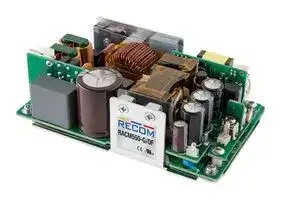


RACM550-48SG/OF
AC/DC Open Frame Power Supply (PSU), ITE, 1 Output, 550W, 300 W, 80V AC to 264V AC
- Manufacturer: RECOM POWER
- Product type: AC / DC Open Frame Power Supplies
- SVHC: No SVHC (25-Jun-2025)
- Product Range: RACM550-G Series
- No. of Outputs: 1 Output
- Current, Output 4: -
- Input Voltage VAC: 80V AC to 264V AC
- Power Supply Output Type: Adjustable, Fixed
- Output Current - Output 1: 11.46A
- Output Current - Output 2: -
- Output Current - Output 3: -
- Output Voltage - Output 1: 48VDC
- Output Voltage - Output 2: -
- Output Voltage - Output 3: -
- Output Voltage - Output 4: -
- Power Supply Applications: ITE
- Power Rating (Forced Cooling): 550W
- Power Rating (Convection Cooling): 300W
| Delivery and price | |
|---|---|
| Units per pack | 10 |
| Price | 104.42 € |
| Current stock | 10+ |
| Lead time | 30 days |
Features • 300W baseplate-cooled, fan-less operation • 550W peak power or forced air rating **AC/DC Converter** • Universal AC input range (80~264VAC) Regulated • Standby power consumption <0.5W • Operating temperature -40°C to +70°C Converter • Signals: remote sensing and ON/OFF control **RACM550-G** ee ~~__~~ Description **550 Watt** The RACM550 Series is designed to support up to 300 Watt continuous output power without **5” x 3”** fan cooling. The compact 5” x 3” baseplate design enables direct heat dissipation through metal housings in the application. Up to 550 watts are available to drive dynamic loads for several seconds of peak power or with forced air for even longer time frames. A smart fan output is on board as standard **Open Frame or** as well as a 5V/1A VSB output for applications with housekeeping circuits and on/off control. A wide input range of 80 to 264VAC, up to 5000m operating altitude and international safety **Enclosed** agency certifications make the series worldwide compliant for medical 2 MOPP, household and industrial ITE applications. **Single Output** ity LMiy lin Selection Guide Part Input Nom. Output Max. Output Efficiency Number Voltage Range Voltage Current[(1)] typ.[(2)] iy[“4] [VAC] [VDC] [A] [%] RACM550-24SG[ (3)] 80-264 24 22.92 93 ~~OO~~ ~ UR RACM550-36SG[ (3)] 80-264 36 15.28 93 RACM550-48SG[ (3)] 80-264 48 11.46 93 RACM550-56SG[ (3)] 80-264 56 9.82 94

Notes:

Note1: With forced air cooling (2.5m/s) + conduction cooling + refer to _“Line Derating”_ Note2: Efficiency is tested at nominal input and full load at +25°C ambient

Model Numbering —— RACM550-__ SG/ max. Output Power _“Case Option[(3)] ”_ _ ~~—— —~~ nom. Output Voltage ~~—~~ **S** ingle Notes: Note3: add suffix “/OF” for open frame version add suffix “/ENC” for enclosed version

Ordering Examples: RACM550-24SG/OF 24Vout Single open frame RACM550-36SG/ENC 24Vout Single enclosed

**==> picture [18 x 21] intentionally omitted <==**

**----- Start of picture text -----**<br>
ERP<br>compliant<br>LOT6<br>**----- End of picture text -----**<br>


**2MOPP**

UL62368-1 (TÜV NRTL) certified CAN/CAS C22.2 No. 62368-1 certified IEC/EN62368-1 certified IEC/EN60950-1 (pending) IEC/EN60335-1 (pending) IEC/EN60601-1 (pending) ANSI/AAMI ES60601-1 (pending) CSA/CAN 22.2 60950-1-14 (pending) IEC/EN61558-1 (pending) IEC/EN61558-2-16 (pending) EN55032 compliant EN55024 compliant CB Report

REV.:  0/2019

PA-1

**www.recom-power.com**

**Series**

## **RACM550-G**

## **AC/DC Converter**

Specifications (measured @ Ta= 25°C, rated input, rated load unless otherwise stated)

BASIC CHARACTERISTICS ~~OT a~~ Parameter ~~eC~~ Condition Min. Typ. Max. nom. Vin= 230VAC 80VAC 230VAC 264VAC Input Voltage Range[(4)] 120VDC 370VDC ~~a~~ 115VAC 6.5A Input Current 230VAC 3.0A ~~a~~ 115VAC 40A Inrush Current 230VAC 60A ~~aee~~ No load Power Consumption 2W Standby Power main output OFF,  VSB Output unloaded 0.5W ~~esGG~~ Input Frequency Range ~~ee~~ AC input 47Hz ~~ee~~ 63Hz ErP Lot 6 Standby Mode Conformity Input Power= 1W (main output= standby mode) 450mW ~~a~~ (VSB Output Load Capability) Minimum Load 0% ~~GG~~ 115VAC 0.98 0.99 Power Factor 230VAC 0.95 0.97 ~~a~~ main output 115VAC/230VAC 400ms Start-up Time ~~a~~ VSB Output 115VAC/230VAC 140ms main output 115VAC/230VAC 15ms Rise Time ~~a~~ VSB Output 115VAC/230VAC 5ms main output 115VAC/230VAC, 550W 15ms Hold-up Time ~~a~~ VSB Output 115VAC/230VAC 130ms main output 1% of Vout nom. max. Output Ripple and Noise[ (5)] 20MHz BW @ 25°C VSB Output 120mVp-p ~~ee ees eee eee~~ Notes: Note4:  The products were submitted for safety files at AC-input operation. For DC-input make sure that sufficient fuses are used Note5:  Measurements are made with a 12“ twisted pair-wire terminated with a 0.1µF and 10µF parallel capacitor

Efficiency vs. Load 100 90 ~~ss~~ 80 ~~Aree~~ 70 ~~AEE~~ 60 ~~fA~~ 50 ~~|~~ 40 ~~(a~~ 30 ~~POP rere~~ 20 115VAC 10 230VAC 0 ~~etEEPE E+ = 4~~ 0 10 20 30 40 50 60 70 80 90 100 Output Load [%] REGULATIONS Parameter Condition Value main output ±3.0% max. Output Accuracy VSB output ±4.0% max. Line Regulation low line to high line, full load main output / VSB output ±1.0% max. Load Regulation[(6)] 10% to 100% load main output / VSB output 1.0% max. Notes: Note6: Operation below 10% load will not harm the converter, but specifications may not be met

## REGULATIONS

Parameter

REV.:  0/2019

PA-2

**www.recom-power.com**

## **RACM550-G**

> **AC/DC Converter Series** Specifications (measured @ Ta= 25°C, rated input, rated load unless otherwise stated) ADDITIONAL FEATURES Parameter Condition Min. Typ. Max. CTRL ON 115VAC/230VAC 5W VSB Output Power 230VAC 5W CTRL OFF 115VAC 1W Output Voltage Adjustability[ (7)] on-board potentiometer ±2VDC CON3, Pin3 main + FAN output ON 2.4VDC - 5VDC or open ON/OFF CTRL (refer to _“VSB & CTRL (CON3)“_ main + FAN output OFF 0VDC - 0.8VDC or shorted to GND continuous 250mA Fan Output Power @ +50°C (not protected) peak (1s) 500mA Remote Sense[  (8)] 2VDC LED = green working Power OK LED LED = red failure ~~=e~~ Notes: Note7:  By trimming up, decrease output current to avoid exceeding rated output power. By trimming down, do not exceed maximum continuous output current Note8:    The output voltage can be adjusted by both ADJ (potentiometer) and Sense. The maximum combined adjustment range is ±2VDC ~~Ema~~ REMOTE SENSE VACIN (L) +Vout RW1 +Vout

> VACin(L) +Sense PE RW1 ... wire losses + RW2 ... wire losses - -Sense VACIN (N) VACin(N) -Vout -Vout RW2 PROTECTIONS (Fan output not protected) Parameter Type Value Input Fuse[(9)] internal 2x T6.3A, slow blow type Over Voltage Category (OVC) OVCII Class of Equipment Class I Isolation Voltage (safety certified)[(10)] I/P to O/P 1 minute 4kVAC Isolation Resistance 10M Ω min. Insulation Grade reinforced Leakage Current 0.25mA max. Means of Protection 250VAC working voltage 2MOPP Notes: Note9: Refer to local safety regulations if input over-current protection is also required. Recommended fuse: slow blow type Note10: For repeat Hi-Pot testing, reduce the time and/or the test voltage PROTECTIONS MAIN OUTPUT Short Circuit Protection (SCP) below 100m Ω Pin =10W max. hiccup mode, auto recovery Over Voltage Protection (OVP) 110% - 120%, hiccup mode Over Current Protection (OCP) 105% - 135%, hiccup mode ~~——~~ Over Temperature Protection (OTP) auto recovery, internal temperature sensors PROTECTIONS AUX (VSB) Short Circuit Protection (SCP) below 100m Ω hiccup mode, auto recovery Over Voltage Protection (OVP) 8-9VDC, hiccup mode ~~==~~ Over Current Protection (OCP) 2.5-3.5A, hiccup mode **www.recom-power.com** REV.:  0/2019 PA-3

**AC/DC Converter**

**Series**

## **RACM550-G**

Specifications (measured @ Ta= 25°C, rated input, rated load unless otherwise stated) ~~_[iii]~~ ENVIRONMENTAL ~~TT~~ Parameter Condition Value ~~a O fe~~ Operating Temperature Range refer to derating graphs -40°C to +70°C Temperature Coefficient ±0.02%/K ~~ee~~ Operating Altitude[(11)] 5000m ~~ee~~ Operating Humidity non-condensing 20% - 90% RH max. ~~a~~ Pollution Degree PD2 ~~ee~~ Shock 250m/s², 6ms; 3 times, each along x, y, z axes ~~eG~~ Vibration 90-200Hz, 10m/s²; 3.5min./1cycle, 5 periods, each along x, y, z axes according to MIL-217F Method 2 +25°C (forced air cooling) 200 x 10[3] hours MTBF Components Stress Method +45°C (forced air cooling) 50 x 10[3] hours Notes: Note11: Recognized by safety agency for safe operation up to 5000m. High altitude operation may impact the performance and lifetime. Please contact RECOM tech support for advice. Thermal Derating 115VAC Line Derating (<115VAC) 550 ~~a~~ 100 ~~nett snsmtntmsnsnsmtetmsndees~~ 500 ~~COTTE~~ 90 ~~ee~~ 450 ~~COCA~~ 80 ~~ns~~ 400 ~~PEPE~~ 70 ~~Psees~~ 350 60 ~~{ttt tT AH A~~ 300 ~~ppp et~~ 50 ~~es~~ 250 ~~CCCEC CCS~~ 40 ~~To~~ 200 ~~Pf tt tT | Pa ed~~ 30 150 ~~ne Pp |[pd]~~ 100 115VAC, 4.5m/s forced cooling ~~nae~~ 20 ~~|~~ 50 115VAC, conduction cooling ~~115VAC, convection cooling a2~~ 10 ~~es~~ 0 ~~nan~~ 0 ~~ee~~ -40 -30 -20 -10 0 10 20 30 404550 60 70 80 80 90 100 115 Ambient Temperature [°C] Input Voltage [VAC] Thermal Derating 230VAC 550 500 ~~Ne~~ 450 ~~aN~~ 400 ~~PT tT~~ | ~~dT dP rT TT~~ 350 ~~Ft tt TdT dT dT~~ ~~**T** TXTIN~~ 300 ~~fener~~ 250 ~~Pfel| |~~ 200 ~~Pt tT~~ | | ~~dP TT |~~ 150 ~~Pt tT~~ | | ~~| | EdPdtt~~ 230VAC, 2.5m/s forced cooling ~~ti |~~ 100 50 230VAC, conduction cooling ~~230VAC, convection cooling i ||~~ 0 | -40 -30 -20 -10 0 10 20 30 40 50 60 70 80 Ambient Temperature [°C]

<0.1m/s = still air 0.1 - 0.2m/s = natural convection

continued on next page

REV.:  0/2019

PA-4

**www.recom-power.com**

## **RACM550-G**

## **AC/DC Converter**

## **Series**

Specifications (measured @ Ta= 25°C, rated input, rated load unless otherwise stated)

## Peak Load Capability

Pout [W]

## Calculation

Pnom = nom. output power [W] PP = peak output power (≤550W) [W] Pr = recovery output power [W] Pnom x (t1set + t2) - (PP x t1set) t1 = peak time set (10s max.) [s] Pr = t2 x k t2 = recovery time (min. 4 x t1) [s] k = safety factor 1.7 [ ]

## - Practical Example (RACM550 24SG/OF):

**==> picture [168 x 113] intentionally omitted <==**

**----- Start of picture text -----**<br>
Pp<br>Pnom<br>Pr<br>0 Time [s]<br>t1 t2<br>**----- End of picture text -----**<br>


Take the RACM550-24SG/OF at 100VAC input voltage and  TAMB= 60°C (220W) with conduction cooling.

Pnom.  = refer to derating graphs= 245W with line derating 220W

PP = 550W

tt12 = 10s   =[40s] Pr = 220 x (10 + 40) - (550 x 10)40 x 1.7 = 80.9W k = 1.7

|Pout [W]<br>t11<br>t22<br>Ppp<br>Pnomnom<br>0<br>Prr<br>Time [s]<br>Peak Load Capability<br>Calculation<br>Pnom.  = refer to derating graphs= 245W with line derating 220Wnom.  = refer to derating graphs= 245W with line derating 220W= refer to derating graphs= 245W with line derating 220W<br>PP = 550WP = 550W= 550W <br>t1212<br>= 10s   =<br>tt122<br>=[40s]<br>k<br>= 1.7<br>Pr =r ==<br>Pnom x (t1set + t2) - (PP x t1set)nom x (t1set + t2) - (PP x t1set)x (t1set + t2) - (PP x t1set)1set + t2) - (PP x t1set)+ t2) - (PP x t1set)2) - (PP x t1set)) - (PP x t1set)P x t1set)x t1set)1set))<br>t2 x k2 x kx k<br>Pnomnom= nom. output power<br>[W]<br>PPP<br>= peak output power (≤550W) [W]≤550W) [W]550W) [W] <br>Prr<br>= recovery output power<br>[W]<br>t11<br>= peak time set (10s max.)<br>[s]<br>t22<br>= recovery time (min. 4 x t1)1))<br>[s]<br>k<br>= safety factor 1.7<br>[ ]<br>Practical Example (RACM550-24SG/OF):<br>Pr =r ==<br>220 x (10 + 40) - (550 x 10)40 x 1.7<br>= 80.9W80.9W<br>40 x 1.7<br>Take the RACM550-24SG/OF at 100VAC input voltage and  TAMB= 60°C (220W) withAMB= 60°C (220W) with= 60°C (220W) with<br>conduction cooling.<br>Preliminary|Pout [W]<br>t11<br>t22<br>Ppp<br>Pnomnom<br>0<br>Prr<br>Time [s]<br>Peak Load Capability<br>Calculation<br>Pnom.  = refer to derating graphs= 245W with line derating 220Wnom.  = refer to derating graphs= 245W with line derating 220W= refer to derating graphs= 245W with line derating 220W<br>PP = 550WP = 550W= 550W <br>t1212<br>= 10s   =<br>tt122<br>=[40s]<br>k<br>= 1.7<br>Pr =r ==<br>Pnom x (t1set + t2) - (PP x t1set)nom x (t1set + t2) - (PP x t1set)x (t1set + t2) - (PP x t1set)1set + t2) - (PP x t1set)+ t2) - (PP x t1set)2) - (PP x t1set)) - (PP x t1set)P x t1set)x t1set)1set))<br>t2 x k2 x kx k<br>Pnomnom= nom. output power<br>[W]<br>PPP<br>= peak output power (≤550W) [W]≤550W) [W]550W) [W] <br>Prr<br>= recovery output power<br>[W]<br>t11<br>= peak time set (10s max.)<br>[s]<br>t22<br>= recovery time (min. 4 x t1)1))<br>[s]<br>k<br>= safety factor 1.7<br>[ ]<br>Practical Example (RACM550-24SG/OF):<br>Pr =r ==<br>220 x (10 + 40) - (550 x 10)40 x 1.7<br>= 80.9W80.9W<br>40 x 1.7<br>Take the RACM550-24SG/OF at 100VAC input voltage and  TAMB= 60°C (220W) withAMB= 60°C (220W) with= 60°C (220W) with<br>conduction cooling.<br>Preliminary|Pout [W]<br>t11<br>t22<br>Ppp<br>Pnomnom<br>0<br>Prr<br>Time [s]<br>Peak Load Capability<br>Calculation<br>Pnom.  = refer to derating graphs= 245W with line derating 220Wnom.  = refer to derating graphs= 245W with line derating 220W= refer to derating graphs= 245W with line derating 220W<br>PP = 550WP = 550W= 550W <br>t1212<br>= 10s   =<br>tt122<br>=[40s]<br>k<br>= 1.7<br>Pr =r ==<br>Pnom x (t1set + t2) - (PP x t1set)nom x (t1set + t2) - (PP x t1set)x (t1set + t2) - (PP x t1set)1set + t2) - (PP x t1set)+ t2) - (PP x t1set)2) - (PP x t1set)) - (PP x t1set)P x t1set)x t1set)1set))<br>t2 x k2 x kx k<br>Pnomnom= nom. output power<br>[W]<br>PPP<br>= peak output power (≤550W) [W]≤550W) [W]550W) [W] <br>Prr<br>= recovery output power<br>[W]<br>t11<br>= peak time set (10s max.)<br>[s]<br>t22<br>= recovery time (min. 4 x t1)1))<br>[s]<br>k<br>= safety factor 1.7<br>[ ]<br>Practical Example (RACM550-24SG/OF):<br>Pr =r ==<br>220 x (10 + 40) - (550 x 10)40 x 1.7<br>= 80.9W80.9W<br>40 x 1.7<br>Take the RACM550-24SG/OF at 100VAC input voltage and  TAMB= 60°C (220W) withAMB= 60°C (220W) with= 60°C (220W) with<br>conduction cooling.<br>Preliminary|
|---|---|---|
|SAFETY AND CERTIFICATIONS<br>Preliminary|||
|Certificate Type(Safety)<br>Preliminary|Report / File Number<br>Preliminary|Standard<br>Preliminary|
|Audio/video, information and communication technologyequipment - Safetyrequirements(CB)<br>Preliminary|211-700545-000<br>Preliminary|IEC62368-1:2014 2nd Edition<br>Preliminary|
|Audio/video, information and communication technologyequipment - Safetyrequirements<br>Preliminary||EN62368-1:2014 + A11:2017<br>Preliminary|
|Audio/video, information and communication technology equipment - Safety requirements<br>(TÜV NRTL)<br>Preliminary|65.250.19.032.02<br>Preliminary|UL62368-1:2014<br>Preliminary|
|||CAN/CSA C22.2 No.62368-1:2014<br>Preliminary|
|Information Technology Equipment, General Requirements for Safety<br>Preliminary|pending<br>Preliminary|IEC60950-1:2005, 2nd Edition + A2:2013<br>EN60950-1:2006 + A2:2013<br>Preliminary|
|Household and similar electrical appliances - Safety- Part 1: General requirements<br>Preliminary|pending<br>Preliminary|EN60335-1:2012 + A11:2014<br>Preliminary|
|Measurement methods for electromagnetic fields of household appliances and similar<br>apparatus with regard to human exposure<br>Preliminary|Preliminary|EN62233:2008<br>Preliminary|
|Medical Electric Equipment, General Requirements for Safety and Essential Performance<br>Preliminary|pending<br>Preliminary|ANSI/AAMI ES60601-1:2005<br>CAN/CSA-C22.2 No. 6060-1:14<br>Preliminary|
|Medical Electric Equipment, General Requirements for Safetyand Essential Performance(CB)<br>Preliminary|pending<br>Preliminary|IEC60601-1:2005, 3rd Edition + AM1:2012<br>Preliminary|
|Medical Electric Equipment, General Requirements for Safetyand Essential Performance<br>Preliminary||EN60601-1:2006 + A12:2014<br>Preliminary|
|Safety of transformers, reactors, power supply units and combinations thereof<br>Part 1: General requirements and tests<br>Preliminary|pending<br>Preliminary|IEC61558-1:2005, 2nd Edition + A1:2009<br>EN61558-1:2005 + A1:2009<br>Preliminary|
|Safety of transformers, reactors, power supply units and similar products for supply<br>voltages up to 1100 V - Part 2-16: Particular requirements and tests for switch mode<br>power supply units and transformers for switch mode power supply units (CB)<br>Preliminary|pending<br>Preliminary|IEC61558-2-16:2009, 1st Edition + A1:2013<br>Preliminary|
|Safety of transformers, reactors, power supply units and similar products for supply<br>voltages up to 1100 V - Part 2-16: Particular requirements and tests for switch mode<br>power supply units and transformers for switch mode power supply units (LVD)|pending|EN61558-2-16:2009 + A1:2013|
|RoHS2||RoHS 2011/65/EU + AM2015/863|
|continued on nextpage|||


continued on next page

REV.:  0/2019

PA-5

**www.recom-power.com**

**AC/DC Converter**

**Series**

## **RACM550-G**

~~Lo~~ Specifications (measured @ Ta= 25°C, rated input, rated load unless otherwise stated) ~~eG~~ EMC Compliance Condition Standard / Criterion ~~a~~ Electromagnetic compatibility of multimedia equipment - Emission requirements without external filter EN55032:2015, Class B ~~ee~~ Electromagnetic compatibility of multimedia equipment - Immunity requirements EN55035:2017 Information technology equipment - Immunity characteristics - EN55024:2010 + A1:2015 ~~a~~ Limits and methods of measurement ESD Electrostatic discharge immunity test Air ±8kV, Contact ±4kV EN61000-4-2:2009, Criteria A ~~eG~~ Radiated, radio-frequency, electromagnetic field immunity test 3V/m (80-5000MHz) EN61000-4-3:2006+A2:2010, Criteria A ~~ee~~ Fast Transient and Burst Immunity AC Power Port: ±1kV EN61000-4-4:2012, Criteria A Surge Immunity AC Power Port: L-N ±1kV EN61000-4-5:2014, Criteria B AC Power Port: 3V (0.15-10MHz) Immunity to conducted disturbances, induced by radio-frequency fields 3V to 1V (10-30MHz) EN61000-4-6:2014, Criteria A ~~eeee~~ 1V (30-80MHz) ~~ee |~~ Power Magnetic Field Immunity 50Hz/60Hz, 1A/m EN61000-4-8:2010, Criteria A ~~ee~~ Voltage Dips and Interruptions Voltage Dips 100% at 50/60Hz EN61000-4-11:2004, Criteria A ~~rs~~ Voltage Dips and Interruptions Voltage Dips 30% at 50Hz EN61000-4-11:2004, Criteria A ~~eG~~ Voltage Dips and Interruptions Voltage Dips 30% at 60Hz EN61000-4-11:2004, Criteria B Voltage Dips and Interruptions Voltage Interruptions > 95% at 50Hz EN61000-4-11:2004, Criteria C ~~Re Re~~ Voltage Dips and Interruptions Voltage Interruptions > 95% at 60Hz EN61000-4-11:2004, Criteria B Limits of Harmonic Current Emissions EN61000-3-2:2014 ~~a~~ Limits of Voltage Fluctuations & Flicker EN61000-3-3:2013 ~~Cn~~

**==> picture [525 x 335] intentionally omitted <==**

**----- Start of picture text -----**<br>
DIMENSION AND PHYSICAL CHARACTERISTICS<br>a<br>es Parameter Type Value<br>PCB FR4, (UL94 V-0)<br>Material<br>a baseplate/case aluminium<br>open frame version 127.0 x 76.0 x 38.0mm<br>Dimension (LxWxH)<br>enclosed version 150.0 x 87.0 x 45.0mm<br>ee ee<br>open frame version 500g typ.<br>Weight<br>enclosed version 590g typ.<br>ee ee<br> Dimension Drawing Open Frame (mm)<br>127.0<br>CON3<br>———————<br>CON6<br>ADJ<br>Top View 1 2<br>3 4<br>CON7<br>Paee<br>CON8<br>CON4 P o h e<br>CON2<br>CON1 2 1<br>— ae —e<br>LED<br>76.0<br>**----- End of picture text -----**<br>


continued on next page

REV.:  0/2019

PA-6

**www.recom-power.com**

**AC/DC Converter**

~~|~~ Specifications (measured @ Ta= 25°C, rated input, rated load unless otherwise stated)

# **RA** ~~**CM**~~ **550-G Series**

Side View **airflow** ~~E~~ < FC 115.8 FC 5.6 4 x Ø3.5 Bottom View FC = fixing centers Tolerance: xx.x= ±1.0mm xx.xx= ±0.5mm ~~Le,~~ **CON3** 3 4 DC side 1 2 AC side **LED CON2 CON8 CON7 CON6 CON1 CON4** 1 3 **ADJ** ~~cE i~~ Compatible Connector (valid for open frame and enclosed version) PE (CON1) AC Input (CON4) FAN (CON2) VSB & CTRL (CON3) Sense (CON6) ~~#~~ Function Connector # Function Connector # Function Connector # Function Connector # Function Connect ~~or~~ 1 +5VSB 1 -Sense TE Connectivity 1 AC/N Molex 09-501 -FAN Molex 22-012 GND Molex 511102 NC Molex 511101 PE PIDG series with 3 AC/L 1031 or similar 2 +FAN 1022 or similar 3 PS ON 0450 or similar 3 +Sense 0450 or similar positive lock .250EX 4 GND 4 NC

NC= No connection

MAIN Output Screw Terminal (CON7/8)

# Function AWG CON7 -Vout 14-26 CON8 +Vout 14-26 wire stripping length: 5.0mm recommended tightening torque: 0.8Nm

Maximum tightening torque for mounting: 0.3Nm

FC = fixing centers Tolerance: xx.x= ±1.0mm xx.xx= ±0.5mm

continued on next page

REV.:  0/2019

PA-7

**www.recom-power.com**

## **RACM550-G**

## **AC/DC Converter**

## **Series**

Specifications (measured @ Ta= 25°C, rated input, rated load unless otherwise stated)

Dimension Drawing Enclosed Version (mm)

150.0

**==> picture [495 x 585] intentionally omitted <==**

**----- Start of picture text -----**<br>
CON4<br>1 2 CON1<br>CON2<br>Top View<br>CON8<br>CON7<br>CON6<br>1 2 ADJ<br>3 4<br>2 ) Nu<br>Ø4.5<br>Ø4.5<br>Side View embossed logo<br>5.0 130.0 10.0<br>FC 134.5 FC 7.75<br>4 x Ø4.5<br>Ø4.5<br>Bottom View<br>FC = fixing centers<br>Tolerance: xx.x= ±1.0mm<br>                xx.xx= ±0.5mm<br>0<br>7.<br>8<br>05.<br>4<br>5<br> 27.<br>C<br>FC 27.5 F<br>35.<br> 4<br>C<br>F<br>FC 58.5<br>FC 14.25<br>**----- End of picture text -----**<br>


continued on next page

REV.:  0/2019

PA-8

**www.recom-power.com**

## **RACM550-G**

## **AC/DC Converter**

## **Series**

Specifications (measured @ Ta= 25°C, rated input, rated load unless otherwise stated)

**==> picture [485 x 668] intentionally omitted <==**

**----- Start of picture text -----**<br>
 Dimension Drawing Enclosed Version (mm)<br>DC side 3 oa 4 AC side<br>1 2<br>LED CON2 CON8 CON7 CON6 CON4 CON1<br>T EE —— I EE!<br>1<br>Y H | C<br>| m L Al / a ay rr “ 3 y/<br>DOL? Se s = EF<br>ADJ<br>SL AP Poe i : a<br>E ES To i Ae<br>| eg |<br>INSTALLATION AND APPLICATION<br>Mounting Forced air conditions as specified are valid for indicated airflow direction only!<br>vertical<br>horizontal (standard) upside down<br>airflow A C DC<br>airflow<br>AC DC<br>side side Notes:<br>No t e12: If module is horizontal or side mounted no derating is required.<br> If module is mounted vertically or upside down with natural convection cooling, the<br> power must be derated at least 10%. With forced air cooling, mounting orientation<br> has no impact  on  output power.<br>For convection cooling, ensure suffici e nt distance to adjac e nt components!<br> De vice should b e  f an cooled from DC side.<br>Block Diagram<br>PS ON<br>Isolation GND<br>ADJ<br>ee +Sense<br>PFC LLC Feedback PWM<br>Controller and Isolation Controller -Sense<br>L Fuse, Inrush +Vout<br>N LE Current Linitation,Input Filter RectiBulk Capfier + PFC B oost S Switcher eA LE Rectifier OutputFilter -Vout<br>PE +Fan<br>Rectifier<br>; Transformer | -Fan<br>Feedback<br>and Isolation<br>+5VSB<br>Flyback Output<br>Rectifier<br>: Controller  eee Transformer Filter GND<br>ar<br>Prelimin<br>AC<br>DC<br>airflow<br>**----- End of picture text -----**<br>


## INSTALLATION AND APPLICATION

REV.:  0/2019

PA-9

**www.recom-power.com**

**AC/DC Converter**

# **RACM550-G Series**

~~|~~ Specifications (measured @ Ta= 25°C, rated input, rated load unless otherwise stated)

## PACKAGING INFORMATION

|PACKAGING INFORMATION|PACKAGING INFORMATION|PACKAGING INFORMATION|PACKAGING INFORMATION|
|---|---|---|---|
|Parameter|Type||Value|
|Packaging Dimension (LxWxH)<br>Preliminary|cardboard box<br>Preliminary|open frame version<br>enclosed version<br>Preliminary|134.0 x 86.0 x 45.0mm<br>155.0 x 92.0 x 50.0mm<br>Preliminary|
|PackagingQuantity<br>Preliminary|Preliminary||1pcs<br>Preliminary|
|Storage Temperature Range<br>Preliminary|Preliminary||-55°C to +85°C<br>Preliminary|
|Storage Humidity<br>Preliminary|non-condensing<br>Preliminary||95% RH max.<br>Preliminary|


The product information and specifications may be subject to changes even without prior written notice.The product has been designed for various applications; its suitability lies in the responsibility of each customer. The products are not authorized for use in safety-critical applications without RECOM’s explicit written consent. A safety-critical application is an application where a failure may reasonably be expected to endanger or cause loss of life, inflict bodily harm or damage property. The applicant shall indemnify and hold harmless RECOM, its affiliated companies and its representatives against any damage claims in connection with the unauthorized use of RECOM products in such safety-critical applications.

REV.:  0/2019

PA-10

**www.recom-power.com**
Updated at April 28, 2026
RECOM Power is a globally recognized manufacturer specializing in standard and customized power conversion solutions. Headquartered in Austria with state-of-the-art research and development facilities, the company has built a strong reputation for innovation and reliability. Operating from ISO 9001 and IATF 16949 certified manufacturing sites, RECOM delivers premium power supplies engineered for demanding applications across IoT, Industry 4.0, medical technology, and transportation. The core of our RECOM Power portfolio is dedicated to advanced power and line protection, featuring an extensive selection of high-performance AC/DC converters. These modules are designed to provide efficient, stable power distribution for a wide array of industrial and commercial electronics. In addition to general-purpose power supplies, we offer a robust range of AC/DC LED power supplies specifically optimized to meet the stringent efficiency and lifespan requirements of modern lighting systems. To support comprehensive power architecture design, our selection also includes highly efficient DC/DC converters ideal for precise voltage regulation in complex circuits. Furthermore, we provide specialized passive components such as RECOM power inductors, ensuring engineers have access to the critical, high-quality components required to develop resilient and optimized power delivery systems.
About Novapart
Novapart is a B2B electronic component broker specialising in stock shortages and cost reduction. We source hard-to-find parts and identify compliant alternatives across a catalogue of 410,000+ components from 500+ manufacturers.
Learn more →Stock Shortage Specialist
When a component is unavailable, discontinued or has an unacceptable lead time, we tap into our network of vetted European and Asian distributors to source what you need — without compromising on quality or traceability.
Request a quote →Compliant Alternatives
We identify pin-to-pin, electrically equivalent substitutes that meet the same certifications (RoHS, AEC-Q100, REACH) as your original specification — validated against datasheets, not just part numbers. Often at a lower cost.
BOM Analysis service →