
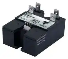


RA2A23D40C.
SOLID STATE RELAY, 40A, 4.5VDC-32VDC
- Manufacturer: CARLO GAVAZZI
- Product type:
- Contact Configuration:DPST; Load Current:40A; Operating Voltage Max:265VAC; Relay Mounting:Panel Mount; Relay Terminals:Quick Connect; Switching Mode:Zero Crossin 90Y7519
- SVHC: No SVHC (21-Jan-2025)
- Load Current: 40A
- Product Range: RA2A Series
- Relay Mounting: Panel Mount
- Switching Mode: Zero Crossing
- Relay Terminals: Quick Connect
- Control Voltage Max: 32VDC
- Control Voltage Min: 4.5VDC
- Contact Configuration: DPST
- Operating Voltage Max: 265VAC
- Operating Voltage Min: 24VAC
| Delivery and price | |
|---|---|
| Units per pack | 100 |
| Price | 83.75 € |
| Current stock | 10+ |
| Lead time | 30 days |
**RA2A..C**

## **RA2A..C**

## **2-pole solid state relays**

## **Main features**

- AC switching solid state relay

- Zero cross switching

- Back to back thyristor output

- Direct copper bonding (DCB) technology

- For resistive AC loads

- Integrated output overvoltage protection

- DC control voltage

- LED for control presence indication for each independent pole

- 6.35 mm Faston termination for the output terminals and 4-pin header for the control terminals

## **Description**

This 2-pole industrial relay minimises the space requirements in a control cabinet without compromising performance. By applying an input voltage on control A, the corresponding output semiconductor is activated at the first zero crossing of line voltage. The same applies to control B.

LEDs indicate the control status of each pole. The optimised design is free of moulding mass to reduce internal mechanical stress.

The integrated varistor across the output of each pole ensures protection against overvoltages.

Specifications are at a surrounding temperature of 25°C unless otherwise specified.

## **Applications**

Plastic injection machines, extrusion machines, blow moulding machines, thermoformers, coffee machines, electrical ovens, fryers, shrink tunnels, reflow ovens.

## **Main functions**

- 2 independent pole switching solid state relay

- Zero cross switching

- Ratings up to 600 VAC, 40 AAC per pole

- 4.5 - 32 VDC control voltage range

**1**

15/11/2022 RA2A..C DS ENG

Carlo Gavazzi Ltd.

**RA2A..C**

**==> picture [37 x 37] intentionally omitted <==**

**==> picture [483 x 53] intentionally omitted <==**

**----- Start of picture text -----**<br>
Order code<br>RA2A   D   C<br>**----- End of picture text -----**<br>


Enter the code option instead of . Refer to selection guide section for valid part numbers.

**==> picture [484 x 181] intentionally omitted <==**

**----- Start of picture text -----**<br>
Code Option Description Comments<br>R -<br>A - Solid State Relay (RA)<br>2 - 2-pole switching<br>A - Zero cross switching (ZC)<br>23 Rated voltage: 24-265 VAC, 650 Vp<br>60 Rated voltage: 42-660 VAC, 1200 Vp<br>D Control voltage: 4.5-32 VDC<br>25 Rated current: 2 x 25 AAC<br>40 Rated current: 2 x 40 AAC<br>C - PIN connectors for control<br>-<br>H53 RA2A mounted on heatsink RHS38AD<br>S18 Pre-attached thermal pad<br>**----- End of picture text -----**<br>


**2**

15/11/2022 RA2A..C DS ENG

Carlo Gavazzi Ltd.

**RA2A..C**

**==> picture [37 x 37] intentionally omitted <==**

## **Selection guide**

**==> picture [483 x 76] intentionally omitted <==**

**----- Start of picture text -----**<br>
Rated voltage,  Maximum rated operational current*<br>Switching mode Control voltage<br>Blocking voltage 2 x 25 AAC 2 x 40 AAC<br>230 VAC,<br>RA2A23D25C RA2A23D40C<br>650 Vp<br>Zero cross 4.5 - 32 VDC<br>600 VAC,<br>RA2A60D25C RA2A60D40C<br>1200 Vp<br>**----- End of picture text -----**<br>


- With suitable heatsink

## **Selection guide - RA2A..H53 (RA2A mounted on heatsink RHS38AD)**

|**Rated voltage,**|||**Rated operational current @ 40°C**|
|---|---|---|---|
|**Blocking voltage**|**Switching mode**|**Control voltage**|**2 x 20 AAC***|
|**230 VAC,**<br>**650 Vp**|Zero cross|4.5 - 32 VDC|RA2A23D40CH53|


- Refer to Derating Curve for other ratings

## **Selection guide - RA2A..S18 (Pre-attached thermal pad)**

|**Rated voltage,**<br>**Blocking voltage**|**Switching mode**|**Control voltage**|**Maximum rated operational current***|**Maximum rated operational current***|
|---|---|---|---|---|
||||**2 x 25 AAC**|**2 x 40 AACrms**|
|**230 VAC,**<br>**650 Vp**|Zero cross|4.5 - 32 VDC|-|RA2A23D40CS18|


- With suitable heatsink

## **Carlo Gavazzi compatible components**

**==> picture [483 x 77] intentionally omitted <==**

**----- Start of picture text -----**<br>
Description Component code Notes<br>Graphite thermal pad KK071CUT - Dimensions: 35 x 43 x 0.25 mm<br>- Packing quantity: 50 pcs.<br>Cable RCS4-xxx-1 xxx = 100 for 100 cm length<br>xxx = 400 for 400 cm length<br>Heatsink RHS Heatsinks and accessories<br>**----- End of picture text -----**<br>


## **Carlo Gavazzi further reading**

**==> picture [483 x 53] intentionally omitted <==**

**----- Start of picture text -----**<br>
Information Where to find it Notes<br>Datasheet https://gavazziautomation.com/images/PIM/DATASHEET/ Accessories and heatsink datasheet<br>ENG/SSR_Accessories.pdf<br>https://gavazziautomation.com/nsc/hq/en/solid_state_relays Online Heatsink selector tool<br>**----- End of picture text -----**<br>


**3**

15/11/2022 RA2A..C DS ENG

Carlo Gavazzi Ltd.

**RA2A..C**

**==> picture [37 x 37] intentionally omitted <==**

## **Structure**

**==> picture [483 x 386] intentionally omitted <==**

**----- Start of picture text -----**<br>
B1, B2<br>A1, A2<br>Green LED<br>Green LED<br>Control input<br>Element Component Function<br>A1, A2 Power connections Mains and load connections for pole A<br>B1, B2 Power connections Mains and load connections for pole B<br>Control input Control connection Terminals for control voltage<br>Green LED Control indicator Indicates presence of control voltage (pole A and pole B)<br>**----- End of picture text -----**<br>


**4**

15/11/2022 RA2A..C DS ENG

Carlo Gavazzi Ltd.

**RA2A..C**

**==> picture [37 x 37] intentionally omitted <==**

## **Features**

## **General data**

|**Material**|Noryl, black|Noryl, black|
|---|---|---|
|**Mounting**|Panel mount||
|**Baseplate**|Aluminium||
|**Isolation**|Output to heatsink<br>Input to Output<br>4000<br>4000|Vrms<br>Vrms|
|**Weight**|approx. 60 g<br>approx. 210g (RA2A..H53)||
|**Control terminals1**|4 PIN connector 0.64 mm squarepin with 2.54 mm centre distance||
|**Power terminals**|4 x Fastons; 6.35 x 0.8 mm||
|**Max. Pull out force forpower terminals**|130 N||
|**Relay**<br>**Mounting screws**<br>**Mounting torque**|M5<br>1.5 - 2.0 Nm||


1. Possible mating connector model CE100F22-4-D from MAS-CON

## **Dimensions**

**==> picture [53 x 79] intentionally omitted <==**

**==> picture [460 x 196] intentionally omitted <==**

**----- Start of picture text -----**<br>
34.8<br>29.7 67.4<br>Faston Terminals (x4) 25.7 23.2 Mounting hole3.5 45.5 34.8<br>29.7<br>Faston Terminals (x4) 25.7 23.2<br>A2 B1<br>A1 B2<br>A2 B1<br>Control A Control B A1 B2<br>Control A Control B<br>5.2<br>13 5.2<br>Pins<br>44.5 13<br>Pins<br>44.5<br>Fig. 1: RA2A..C Fig. 2:  RA2A..CH53<br>5.1<br>5.1<br>10.2<br>57.8 47.5<br>10.2<br>76.0 62.8 57.8 47.5<br>16.9<br>16.9<br>**----- End of picture text -----**<br>


Dimensions in mm unless otherwise noted. Tolerances +/- 0.5mm.

**5**

15/11/2022 RA2A..C DS ENG

Carlo Gavazzi Ltd.

**RA2A..C**

**==> picture [37 x 37] intentionally omitted <==**

## **Performance**

## **Output specifications**

**==> picture [483 x 156] intentionally omitted <==**

**----- Start of picture text -----**<br>
RA2A...25 RA2A...40<br>Max. operational current: AC-51  2 x 25 AACrms 2 x 40 AACrms<br>Operational frequency range 45 to 65 Hz<br>Leakage current @ rated voltage < 3 mA<br>Output protection Integrated varistor<br>Power factor ≥ 0.95 @ rated voltage<br>Minimum operational current 150 mA 250 mA<br>Non-repetitive surge current (ITSM),  325 Ap 600 Ap<br>t=10 ms<br>I²t for fusing (t=10 ms), minimum 525 A²s 1800 A²s<br>Critical dV/dt (@Tj init = 40°C) 1000 V/μs<br>**----- End of picture text -----**<br>


## **Output voltage specifications**

**==> picture [483 x 43] intentionally omitted <==**

**----- Start of picture text -----**<br>
RA2A23... RA2A60...<br>Operational voltage range, Ue 24 to 265 VACrms 42 to 660 VACrms<br>Blocking voltage 650 Vp 1200 Vp<br>**----- End of picture text -----**<br>


## **Inputs**

|**Control voltage range2**|4.5 - 32 VDC|
|---|---|
|**Pick-up voltage**|4.25 VDC|
|**Drop-out voltage**|2.0 VDC|
|**Maximum reverse voltage**|32 VDC|
|**Response timepick-up @ 50 Hz**|≤10 ms|
|**Response time drop-out@ 50 Hz**|≤10 ms|
|**Input current per pole @ max. input**<br>**voltage**|≤10 mA|


2. DC control to be supplied by class 2 power source

**6**

15/11/2022 RA2A..C DS ENG

Carlo Gavazzi Ltd.

**RA2A..C**

**==> picture [37 x 37] intentionally omitted <==**

## **Output power dissipation**

**==> picture [373 x 187] intentionally omitted <==**

**----- Start of picture text -----**<br>
50<br>45<br>40<br>35<br>30<br>25<br>RA2A…25C<br>RA2A…40C<br>20<br>15<br>10<br>5<br>0<br>0 5 10 15 20 25 30 35 40 45<br>Load Current per pole in AACrms<br>Power dissipation  per pole in W<br>**----- End of picture text -----**<br>


## **Derating Curve for RA2A..H53**

**==> picture [198 x 127] intentionally omitted <==**

**----- Start of picture text -----**<br>
30<br>0 20 25 40 70<br>2525 25 24 20 12<br>26.4 26.4 25 20.7 12<br>20<br>15<br>10<br>5<br>0<br>0 10 20 30 40 50 60 70<br>Surrounding ambient temperature in °C<br>Load current in AACrms (per pole)<br>**----- End of picture text -----**<br>


## **Applications**

Care must be taken to ensure proper heatsinking when the relay is to be used at high sustained currents. Adequate electrical connection between relay terminals and cable must be ensured.

## **Thermal characteristics**

The thermal design of solid state relays is very important. It is essential that the user makes sure that cooling is adequate and that the maximum junction temperature of the relay is not exceeded.

If the heatsink is placed in a small closed room, control panel or the like, the power dissipation can cause the ambient temperature to rise. The heatsink is to be calculated on the basis of the ambient temperature and the increase in temperature.

**==> picture [221 x 117] intentionally omitted <==**

**----- Start of picture text -----**<br>
Heat Flow<br>Rth j-c Rth c-s Rth s-a<br>Junction Case Heatsink Ambient<br>temperature temperature temperature temperature<br>Thermal resistance: Rth c-s = case to heatsink<br>Rth j-c = junction to case Rth s-a = heatsink to ambient<br>**----- End of picture text -----**<br>


**7**

15/11/2022 RA2A..C DS ENG

Carlo Gavazzi Ltd.

**RA2A..C**

**==> picture [37 x 37] intentionally omitted <==**

## **Heatsink selection**

Note: Add the currents of both poles and compare with datasheets for proper heatsink. Each pole can handle up to the maximum current specified. Example: Each pole of the RA2A23D40C can handle a maximum of 40 A.

## Thermal resistance [°C/W] of RA2A...25

Thermal resistance [°C/W] of RA2A...40

**==> picture [483 x 188] intentionally omitted <==**

**----- Start of picture text -----**<br>
Load  Surrounding ambient temperature  [°C] Load  Surrounding ambient temperature  [°C]<br>current  current<br>20 30 40 50 60 70 20 30 40 50 60 70<br>[A] [A]<br>50 1.11 0.94 0.78 0.62 0.46 0.29 80 0.68 0.56 0.44 0.32 0.19 0.07<br>45 1.36 1.17 0.99 0.80 0.61 0.43 72 0.87 0.73 0.59 0.45 0.31 0.17<br>40 1.68 1.47 1.25 1.03 0.81 0.60 64 1.10 0.94 0.78 0.62 0.45 0.29<br>35 2.06 1.80 1.54 1.29 1.03 0.77 56 1.41 1.22 1.03 0.83 0.64 0.45<br>30 2.5 2.2 1.87 1.56 1.25 0.94 48 1.8 1.6 1.36 1.13 0.90 0.67<br>25 3.1 2.7 2.3 1.9 1.6 1.17 40 2.3 2.0 1.7 1.4 1.1 0.86<br>20 4.0 3.5 3.0 2.5 2.0 1.52 32 3.0 2.6 2.2 1.9 1.5 1.1<br>15 6.0 5.0 4.0 3.5 2.8 2.1 24 4.0 4.0 3.0 2.6 2.0 1.5<br>10 9.0 8.0 7.0 6.0 4.0 3.3 16 6.0 6.0 5.0 4.0 3.0 2.4<br>5 18.0 16.0 14.0 12.0 9.0 7.0 8 13.0 12.0 10.0 8.0 7.0 5.0<br>**----- End of picture text -----**<br>


Note: The thermal resistance values indicated above are applicable if a fine layer of thermal paste, HTS02S, is applied between heatsink and SSR.

Thermal resistance [°C/W] of RA2A...25CS18

Thermal resistance [°C/W] of RA2A...40CS18

**==> picture [483 x 188] intentionally omitted <==**

**----- Start of picture text -----**<br>
Load  Surrounding ambient temperature  [°C] Load  Surrounding ambient temperature  [°C]<br>current  current<br>20 30 40 50 60 70 20 30 40 50 60 70<br>[A] [A]<br>50 0.61 0.44 0.28 0.12 --- --- 80 0.18 0.06 --- --- --- ---<br>45 0.86 0.67 0.49 0.30 0.11 --- 72 0.37 0.23 0.09 --- --- ---<br>40 1.18 0.97 0.75 0.53 0.31 0.10 64 0.60 0.44 0.28 0.12 --- ---<br>35 1.60 1.35 1.09 0.83 0.57 0.32 56 0.91 0.72 0.53 0.33 0.14 ---<br>30 2.17 1.86 1.55 1.24 0.93 0.61 48 1.32 1.09 0.86 0.63 0.40 ---<br>25 2.98 2.59 2.20 1.81 1.43 1.04 40 1.90 1.62 1.33 1.05 0.76 0.47<br>20 4.04 3.54 3.03 2.53 2.02 1.52 32 2.79 3.42 2.05 1.68 1.31 0.94<br>15 5.62 4.92 4.22 3.51 2.81 2.11 24 4.09 3.58 3.07 2.56 2.05 1.54<br>10 9.0 8.0 7.0 6.0 4.40 3.30 16 6.0 6.0 5.0 3.98 3.19 2.39<br>5 18.0 16.0 14.0 12.0 9.0 7.0 8 13.0 12.0 10.0 8.0 7.0 5.0<br>**----- End of picture text -----**<br>


Note: The thermal resistance values indicated above are applicable for models which have an attached thermal pad, KK071CUT. Refer to Accessories section.

## **Thermal data**

**==> picture [483 x 90] intentionally omitted <==**

**----- Start of picture text -----**<br>
RA2A...25 RA2A...40<br>Junction temperature ≤ 125°C ≤ 125°C<br>Rth junction to case<br>  1 pole 1°C/W 1°C/W<br>  2 pole 0.5°C/W 0.5°C/W<br>Rth junction to ambient ≤ 20°C/W ≤ 20°C/W<br>**----- End of picture text -----**<br>


**8**

15/11/2022

RA2A..C DS ENG

Carlo Gavazzi Ltd.

**RA2A..C**

**Compatibility and conformance** > **Approvals** ~~CE Ass FAL EB~~ LVD: EN 60947-4-3 EMCD: EN 60947-4-3 EE: EN 60947-4-3 **Standards compliance** EMC: EN 60947-4-3 UR: UL508 Recognised (E80573), NRNT2 cUR: C22.2 No. 14 (E80573), NRNT8 **UL short circuit current rating** 65k Arms (refer to short circuit current section, Type 1 – UL508)

|**Electromagnetic compatibility (EMC) - Immunity**|**Electromagnetic compatibility (EMC) - Immunity**|
|---|---|
|**Electrostatic discharge (ESD)**|EN/IEC 61000-4-2<br>8 kV air discharge, 4 kV contact (PC2)|
|**Radiated radio frequency**|EN/IEC 61000-4-3<br>10 V/m, from 80 MHz to 1 GHz (PC1)<br>10 V/m, from 1.4 to 2 GHz (PC1)<br>3 V/m,from 2 to 2.7 GHz(PC1)|
|**Electrical fast transient (burst)**|EN/IEC 61000-4-4<br>Output: 2 kV, 5 kHz (PC2)<br>Input: 1 kV,5 kHz(PC1)|
|**Conducted radio frequency**|EN/IEC 61000-4-6<br>10 V/m,from 0.15 to 80 MHz(PC1)|
|**Electrical surge**|EN/IEC 61000-4-5<br>Output, line to line: 1 kV (PC2)<br>Output, line to earth: 2 kV (PC2)<br>Input, line to line: 1 kV (PC2)<br>Input, line to earth: 2 kV (PC2)|
|**Voltage dips**|EN/IEC 61000-4-11<br>0% for 0.5, 1 cycle (PC2)<br>40% for 10 cycles (PC2)<br>70% for 25 cycles (PC2)<br>80% for 250 cycles (PC2)|
|**Voltage interruptions**|EN/IEC 61000-4-11<br>0% for 5000 ms(PC2)|


|**Electromagnetic compatibility (EMC) - Emissions**|**Electromagnetic compatibility (EMC) - Emissions**|
|---|---|
|**Radio interference field**<br>**emission (radiated)**|EN/IEC 55011<br>Class A: from 30 to 1000 MHz|
|**Radio interference voltage**<br>**emissions (conducted)**|EN/IEC 55011<br>Class A (Industrial) with external filters: from 0.15 to 30 MHz|


- Performance Criteria 1 (PC1): No degradation of performance or loss of function is allowed when the product is operated as intended.

- Performance Criteria 2 (PC2): During the test, degradation of performance or partial loss of function is allowed. However when the test is complete the product should return operating as intended by itself.

- Performance Criteria 3 (PC3): Temporary loss of function is allowed, provided the function can be restored by manual operation of the controls.

**9**

15/11/2022 RA2A..C DS ENG

Carlo Gavazzi Ltd.

**RA2A..C**

**==> picture [37 x 37] intentionally omitted <==**

## **Environmental specifications**

|**Operating temperature**|-20°C to +70°C(-4°F to +158°F)|
|---|---|
|**Storage temperature**|-20°C to + 80°C(-4°F to +212°F)|
|**Pollution degree**|2(non-conductivepollution withpossibilites of condensation)|
|**EU RoHS compliant**|Yes|
|**China RoHS**|25|


The declaration in this section is prepared in compliance with People’s Republic of China Electronic Industry Standard SJ/ T11364-2014: Marking for the Restricted Use of Hazardous Substances in Electronic and Electrical Products.

||**Toxic or Harardous Substances and Elements**|**Toxic or Harardous Substances and Elements**|**Toxic or Harardous Substances and Elements**|**Toxic or Harardous Substances and Elements**|**Toxic or Harardous Substances and Elements**|**Toxic or Harardous Substances and Elements**|
|---|---|---|---|---|---|---|
|**Part Name**|Lead<br>(Pb)|Mercury<br>(Hg)|Cadmium<br>(Cd)|Hexavalent<br>Chromium<br>(Cr(Vl))|Polybrominat-<br>ed biphenyls<br>(PBB)|Polybromi-<br>nated diphenyl<br>ethers (PBDE)|
|**Power Unit**<br>**Assembly**|x|O|O|O|O|O|
|O: Indicates that said hazardous substance contained in homogeneous materials fot this part are below the limit<br>requirement of GB/T 26572.<br>X: Indicates that said hazardous substance contained in one of the homogeneous materials used for this part is above<br>the limit requirement of GB/T 26572.|||||||


## 这份申明根据中华人民共和国电子工业标准

## SJ/T11364-2014:标注在电子电气产品中限定使用的有害物质

|零件名称|有毒或有害物质与元素|有毒或有害物质与元素|有毒或有害物质与元素|有毒或有害物质与元素|有毒或有害物质与元素|有毒或有害物质与元素|
|---|---|---|---|---|---|---|
||铅<br>(Pb)|汞<br>(Hg)|镉<br>(Cd)|六价铬<br>(Cr(Vl))|多溴化联苯<br>(PBB)|多溴联苯醚<br>(PBDE)|
|功率单元|x|O|O|O|O|O|
|O:此零件所有材料中含有的该有害物低于GB/T 26572的限定。<br>X: 此零件某种材料中含有的该有害物高于GB/T 26572的限定。|||||||


**10**

15/11/2022 RA2A..C DS ENG

Carlo Gavazzi Ltd.

**RA2A..C**

**==> picture [37 x 37] intentionally omitted <==**

## **Short circuit protection**

## **Protection Co-ordination, Type 1 vs Type 2:**

Type 1 protection implies that after a short circuit, the device under test will no longer be in a functioning state. In type 2 coordination the device under test will still be functional after the short circuit. In both cases, however, the short circuit has to be interrupted. The fuse between enclosure and supply shall not open. The door or cover of the enclosure shall not be blown open. There shall be no damage to conductors of terminals and the conductors shall not separate from terminals. Therese shall be no breakage or cracking of insulating bases to the extent that the integrity of the mounting of live parts is impaired. Discharge of parts or any risk of fire shall not occur.

The product variants listed in the table hereunder are suitable for use on a circuit capable of delivering not more than 65,000A rms Symmetrical Amperes, 600Volts maximum when protected by fuses. Tests at 65,000A were performed with Class J, fast acting: please refer to the table below for maximum allowed ampere rating of the fuse. Use fuses only.

**==> picture [484 x 174] intentionally omitted <==**

**----- Start of picture text -----**<br>
Protection co-ordination Type 1 according to UL 508<br>Prospective short circuit<br>Part No. Max fuse size [A] Class Voltage [VAC]<br>current [kArms]<br>RA2A..25.. 30 J / CC<br>65 40 J Max. 600<br>RA2A..40..<br>20 HSJ20 (Mersen)<br>Protection co-ordination Type 2 (IEC/EN 60947-4-3)<br>Part No. Prospective short circuit  Ferraz Shawmut (Mersen) Voltage [VAC]<br>current [kArms]<br>Max fuse size  Part number<br>[A]<br>RA2A..25.. 25 6.9 gRC 10 - 25<br>10 Max. 600<br>RA2A..40.. 40 6.9xx CP gRC 14x51/40<br>**----- End of picture text -----**<br>


xx= 00 without fuse trip indication xx = 21 with fuse trip indication

**==> picture [484 x 34] intentionally omitted <==**

**----- Start of picture text -----**<br>
Protection co-ordination Type 2 with Minature Circuit Breakers (M.C.B.s)<br>Solid State Relay type ABB Model no. for Z - type  ABB Model no. for B - type  Wire cross sectional area  Minimum length of Cu<br>M. C. B. (rated current) M. C. B. (rated current) [mm [2] ] wire conductor [m] [3]<br>**----- End of picture text -----**<br>


|**Protection co-ordination Type 2 with Minature Circuit Breakers(M.C.B.s)**|**Protection co-ordination Type 2 with Minature Circuit Breakers(M.C.B.s)**|**Protection co-ordination Type 2 with Minature Circuit Breakers(M.C.B.s)**|**Protection co-ordination Type 2 with Minature Circuit Breakers(M.C.B.s)**|**Protection co-ordination Type 2 with Minature Circuit Breakers(M.C.B.s)**|
|---|---|---|---|---|
|**Solid State Relay type**|**ABB Model no. for Z - type**<br>**M. C. B.(rated current)**|**ABB Model no. for B - type**<br>**M. C. B.(rated current)**|**Wire cross sectional area**<br>**[mm2]**|**Minimum length of Cu**<br>**wire conductor[m]3**|
||||||
|RA2A..25<br>(525 A2s)|1-pole<br>S201 - Z4 (4A)<br>S201 - Z6 UC (6A)|S201 - B2 (2A)<br>S201 - B2 (2A)|1.0<br>1.0<br>1.5|21.0<br>21.0<br>31.5|
|RA2A..40<br>(1800 A2s)|1-pole<br>S201 - Z10 (10A)|S201 - B4 (4 A)|1.0<br>1.5<br>2.5|7.6<br>11.4<br>19.0|
||S201 - Z16 (16A)|S201 - B6 (6 A)|1.0<br>1.5<br>2.5<br>4.0|5.2<br>7.8<br>13.0<br>20.8|
||S201 - Z20 (20A)|S201 - B10 (10 A)|1.5<br>2.5|12.6<br>21.0|
||S201 - Z25 (25A)|S201 - B13 (13 A)|2.5<br>4.0|25.0<br>40.0|
||2-pole<br>S202 - Z25 (25A)|S202 - B13 (13 A)|2.5<br>4.0|19.0<br>30.4|


3. Between MCB and Load (including return path which goes back to the mains)

Note: A prospective current of 6 kA and a 230 / 400 V power supply is assumed for the above suggested specifications. For cables with different cross section than those mentioned above please consult Carlo Gavazzi's Technical Support Group. S201 models refer to 1-pole M.C.B., S202 models refer to 2-poles M.C.B.

**11**

15/11/2022 RA2A..C DS ENG

Carlo Gavazzi Ltd.

**RA2A..C**

**==> picture [37 x 37] intentionally omitted <==**

## **Functional diagram**

**==> picture [235 x 140] intentionally omitted <==**

**12**

15/11/2022 RA2A..C DS ENG

Carlo Gavazzi Ltd.

**RA2A..C**

## **Connection Diagram**

**==> picture [441 x 190] intentionally omitted <==**

**----- Start of picture text -----**<br>
A single two pole relay in a three phase application.  A two pole relay and a single pole relay connected on a  A two pole relay and a single pole relay connected on a<br>A single two pole relay in a three phase application.<br>Star and Delta (Economy switch) three phase application. Delta, star and star with a neutral  three phase application. Delta, star and star with a neutral.<br>Star and Delta (Economy switch)<br>point. point.<br>L1 L1<br>L2<br>L2<br>L3<br>L3 N<br>| _ | ro<br>L A2 B1 L A2 B1<br>Us| UY es<br>A1 B2 A1 B2<br>Control A Control B Control A Control B<br>= |<br>oa = Ba—_<br>**----- End of picture text -----**<br>


COPYRIGHT ©2022 Content subject to change. Download the PDF: https://gavazziautomation.com

**13**

15/11/2022 RA2A..C DS ENG

Carlo Gavazzi Ltd.
Updated at June 10, 2026
Founded in Milan in 1931, Carlo Gavazzi is a globally recognized leader in the design and manufacture of high-quality automation components. For nearly a century, the company has driven technological innovation in the industrial and building automation markets. With ISO 9001-certified production facilities across Europe and Asia, Carlo Gavazzi delivers state-of-the-art solutions tailored for demanding applications, including HVAC, renewable energy, semiconductor manufacturing, and electric vehicle charging infrastructure. Our extensive portfolio of Carlo Gavazzi components focuses heavily on their industry-leading switching and sensing technologies. We carry a comprehensive selection of solid state relays, contactors, and power relays engineered for exceptional reliability and thermal performance. Alongside these robust switching solutions, our range features a wide array of precision sensors, with a strong emphasis on proximity switches and light sensors that are critical for automated manufacturing processes, mobile equipment, and access control systems. Beyond core sensing and switching, the Carlo Gavazzi lineup extends into essential power management, circuit protection, and control devices. This includes highly efficient AC/DC converters, thermal magnetic circuit breakers, and advanced panel instrumentation designed to monitor and optimize energy efficiency. From current sensing transformers to motor starters, engineers consistently trust Carlo Gavazzi to provide competitive, dependable, and forward-thinking components for their most complex automation challenges.
About Novapart
Novapart is a B2B electronic component broker specialising in stock shortages and cost reduction. We source hard-to-find parts and identify compliant alternatives across a catalogue of 540,000+ components from 500+ manufacturers.
Learn more →Stock Shortage Specialist
When a component is unavailable, discontinued or has an unacceptable lead time, we tap into our network of vetted European and Asian distributors to source what you need — without compromising on quality or traceability.
Request a quote →Compliant Alternatives
We identify pin-to-pin, electrically equivalent substitutes that meet the same certifications (RoHS, AEC-Q100, REACH) as your original specification — validated against datasheets, not just part numbers. Often at a lower cost.
BOM Analysis service →