
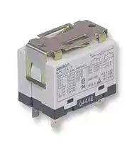


R99-07G5D
Relay Accessory, Mounting Bracket, Omron G7L Series General Purpose Relays
- Manufacturer: OMRON INDUSTRIAL AUTOMATION
- Product type: Other Relay Accessories
- Accessory Type:Mounting Bracket; For Use With:Omron G7L Series General Purpose Relays; Product Range:G7L Series; Clip Type:Ferrite Core Mounting Clip; External Depth:26mm; External Length / Hei
- SVHC: No SVHC (17-Dec-2014)
- Product Range: -
| Delivery and price | |
|---|---|
| Units per pack | 100 |
| Price | 1.69 € |
| Current stock | 100+ |
| Lead time | 30 days |
## **Power Rela G7L y** ~~po~~ **A High-capacity, High-dielectric-strength Relay Compatible with Momentary Voltage Drops**

- No contact chattering for momentary voltage drops up to 50% of rated voltage.

- Wide-range AC-activated coil that handles 100 to 120 or 200 to 240 VAC at either 50 or 60 Hz.

- Miniature hinge for maximum switching power, particularly for inductive loads.

- Flame-resistance materials (UL94V-0-qualifying) used for all insulation material.

- Quick-connect, screw, and PCB terminals, and DIN track mounting available.

RCE

## ~~Ordering Information~~

|**Mounting type**<br>~~le~~<br>~~es~~|**Contact form**<br>~~le~~|**Quick-connect**<br>**terminals**<br>~~le~~|**Screw terminals**<br>~~le~~<br>~~we~~|**PCB**<br>**terminals**<br>~~le~~|
|---|---|---|---|---|
|**E-bracket**<br>~~es~~|SPST-NO|G7L-1A-T|G7L-1A-B<br>~~we~~|---|
||DPST-NO|G7L-2A-T|G7L-2A-B<br>~~we~~|---|
|**E-bracket (with test button)**<br>~~es~~<br>~~———<—_—_—~~|SPST-NO<br>~~———<—_—_—~~|G7L-1A-TJ<br>~~———<—_—_—~~|G7L-1A-BJ<br>~~we~~<br>~~———<—_—_—~~|---<br>~~———<—_—_—~~|
||DPST-NO<br>~~———<—_—_—~~|G7L-2A-TJ<br>~~———<—_—_—~~|G7L-2A-BJ<br>~~we~~<br>~~———<—_—_—~~|---<br>~~———<—_—_—~~|
|**Upper bracket**<br>~~—————~~|SPST-NO<br>~~—————~~|G7L-1A-TUB<br>~~—————~~|G7L-1A-BUB<br>~~—————~~|---<br>~~—————~~|
||DPST-NO<br>~~—————~~|G7L-2A-TUB<br>~~—————~~|G7L-2A-BUB<br>~~—————~~|---<br>~~—————~~|
|**Upper bracket**<br>**(with test button)**<br>~~————<—_——~~|SPST-NO<br>~~————<—_——~~|G7L-1A-TUBJ<br>~~————<—_——~~|G7L-1A-BUBJ<br>~~————<—_——~~|---<br>~~————<—_——~~|
||DPST-NO<br>~~————<—_——~~|G7L-2A-TUBJ<br>~~————<—_——~~|G7L-2A-BUBJ<br>~~————<—_——~~|---<br>~~————<—_——~~|
|**PCB mounting**<br>~~———————~~|SPST-NO<br>~~———————~~|---<br>~~———————~~|---<br>~~———————~~|G7L-1A-P<br>~~———————~~|
||DPST-NO<br>~~———————~~|---<br>~~———————~~|---<br>~~———————~~|G7L-2A-P<br>~~———————~~|


Rated coil voltage

1

~~**G7L**~~

~~**G7L**~~

## **Accessories (Order Separately)**

|**Terminals**<br>**Contact form**<br>**Model**|**R99-07**|**P7LF-D DIN**||**P7LF-06**|
|---|---|---|---|---|
||**E-brackets**|**Track**||**Front-con**|
|||**Mounting**||**necting**|
|||**Adapter**||**Socket**|
|**Quick-connect**<br>SPST-NO<br>G7L-1A-T<br>Yes<br>Yes<br>Yes<br>**terminals**<br>G7L-1A-TJ<br>Yes<br>Yes<br>Yes<br>DPST-NO<br>G7L-2A-T<br>Yes<br>Yes<br>Yes<br>G7L-2A-TJ<br>Yes<br>Yes<br>Yes<br>**Screw terminals**<br>SPST-NO<br>G7L-1A-B<br>Yes<br>Yes<br>No<br>G7L-1A-BJ<br>Yes<br>Yes<br>No<br>DPST-NO<br>G7L-2A-B<br>Yes<br>Yes<br>No<br>G7L-2A-BJ<br>Yes<br>Yes<br>No<br>~~eese~~<br>~~a~~<br>~~ee ee ee~~<br>~~a~~<br>~~ee ee ee~~<br>~~a~~<br>~~eeeee~~<br>~~SS~~|||||
|**Applicable Relay**|**Name**|||**Model**|
|G7L-1A-T/G7L-1A-TJ/G7L-1A-B/G7L-1A-BJ|E-bracket||R99-07||
|G7L-2A-T/G7L-2A-TJ/G7L-2A-B/G7L-2A-BJ|Adapter||P7LF-D||
|G7L-1A-T/G7L-1A-TJ/G7L-2A-T/G7L-2A-TJ|Front-connecting Socket||P7LF-06||
|G7L-1A-B/G7L-1A-BJ/G7L-1A-BUB/G7L-1A-BUBJ<br>Cover|||P7LF-C||
|G7L-2A-B/G7L-2A-BJ/G7L-2A-BUB/G7L-2A-BUBJ|||||
|**Model Number Legend**<br>**G7L -**<br>**-**<br>**1**<br>**2**<br>**3**<br>**4 , 5**<br>~~HO OU~~<br>~~U~~|||||
|**1. Contact Form**<br>**3. Mounting Construction**||**5. Rated Coil Voltage**|||
|1A: SPST-NO<br>Blank:<br>E-bracket||AC: 12, 24, 50, 100 to 120, 200 to 240||AC: 12, 24, 50, 100 to 120, 200 to 240|
|2A: DPST-NO<br>UB:|Upper bracket|DC: 6, 12, 24, 48, 100|||
|**2. Terminal Shape**<br>**4. Special Functions**|||||
|T: Quick-connect terminals<br>Blank:<br>Standard mode|||||
|P: PCB terminals<br>J:|With test button||||
|B: Screw terminals|||||


## **Model Number Legend**

## ~~Application Examples~~

- ! Compressors for air conditioners and heater switching controllers.

- ! Switching controllers for power tools or motors.

- ! Power controllers for water heaters.

- ! Power controllers for dryers.

- ! Lamp controls, motor drivers, and power supply switching in copymachines,facsimilemachines, andotherofficeequipment.

- ! Lighting controllers.

- ! Power controllers for packers or food processing equipment.

- ! Magnetron control in microwaves.

2

~~**G7L**~~

~~**G7L**~~

## ~~Specifications~~

## **Coil Ratings**

|**Coil Ratings**|**Coil Ratings**|||||||
|---|---|---|---|---|---|---|---|
|**Rated voltage**||**Rated**<br>**current**|**Coil resistance**|**Must operate**<br>**voltage**|**Must release**<br>**voltage**|**Max. voltage**|**Power**<br>**consumption**<br>**(approx.)**|
|AC**(**~**)**|12 V|142 mA|---|75% max. of<br>**t** **d**<br>**lt**<br>ra e<br>vo age|15% min. of<br>**t** **d**<br>**lt**<br>ra e<br>vo age|110% of rated<br>**lt**<br>vo age|1.7 to 2.5 VA<br>**(60** **H** **)**<br>z|
||24 V|71 mA|---|||||
||50 V|34 mA|---|||||
||100 to 120 V|17.0 to<br>20.4 mA|---|75 V|18 V|132 V||
||200 to 240 V|8.5 to 10.2 mA|---|150 V|36 V|264 v||
|DC**(**=**)**|6 V|317 mA|18.9"|75% max. of<br>**t** **d**<br>**lt**<br>ra e<br>vo age|15% min. of<br>**t** **d**<br>**lt**<br>ra e<br>vo age|110% of rated<br>**lt**<br>vo age|1.9 W|
||12 V|158 mA|75"|||||
||24 V|79 mA|303"|||||
||48 V|40 mA|1220"|||||
||100 V|19 mA|5260"|||||


**Note:** 1. Theratedcurrentandcoilresistancearemeasuredatacoiltemperatureof23#Cwithtolerances of+15%/--20% forACratedcurrent and $15% for DC coil resistance.

2. Performance characteristic data are measured at a coil temperature of 23#C.

3. ~ indicates AC and = indicates DC (IEC417 publications).

## **Contact Ratings**

|**Model**|**G7L-1A-T**j**/G7L-1A-B**j|**G7L-1A-T**j**/G7L-1A-B**j|**G7L-2A-T**j**/G7L-2A-B**j|**G7L-2A-T**j**/G7L-2A-B**j|**G7L-1A-P/G7L-2A-P**|**G7L-1A-P/G7L-2A-P**|
|---|---|---|---|---|---|---|
||**Resistive load**<br>**(cos**%**= 1)**|**Inductive load**<br>**(cos**%**= 0.4)**|**Resistive load**<br>**(cos**%**= 1)**|**Inductive load**<br>**(cos**%**= 0.4)**|**Resistive load**<br>**(cos**%**= 1)**|**Inductive load**<br>**(cos**%**= 0.4)**|
|**Rated load**|30 A, 220 VAC<br>`(`~)|25 A, 220 VAC<br>`(`~)|25 A, 220 VAC`(`~)||20 A, 220 VAC`(`~)||
|**Rated carry**<br>**current**|30 A||25 A||20 A||
|**Max. switching**<br>**voltage**|250 VAC`(`~)||||||
|**Max. switching**<br>**current**|30 A||25 A||20 A||
|**Max. switching**<br>**power**|6,600 VAC`(`~)|5,500 VAC`(`~)|5,500 VAC`(`~)||4,400 VAC`(`~)||
|**Min. permissible**<br>**load***|100 mA, 5 VDC`(`=)||||||


***Note:** P level: &60 = 0.1 x 10[-6] /operation

3

~~**G7L**~~

~~**G7L**~~

## **Characteristics**

|**Characteristics**||
|---|---|
|**Contact resistance**|50 m"max.|
|**Operate time**|30 ms max.|
|**Release time**|30 ms max.|
|**Max. operating frequency**|Mechanical: 1,800 operations/hr<br>Electrical:<br>1,800 operations/hr(under rated load)|
|**Insulation resistance**|1,000 M"min. (at 500 VDC)|
|**Dielectric strength**|4,000 VAC min., 50/60 Hz for 1 min between coil and contacts<br>2,000 VAC, 50/60 Hz for 1 min between contacts of same polarity<br>2,000 VAC, 50/60 Hz for 1 min between contacts of different polarity (DPST-NO model)|
|**Impulse withstand voltage**|10,000 V between coil and contact (with 1.2 x 50's impulse wave)|
|**Vibration resistance**|Destruction: 10 to 55 Hz, 1.5-mm double amplitude<br>Malfunction: 10 to 55 Hz, 1.5-mm double amplitude|
|**Shock resistance**|Destruction: 1,000 m/s2<br>Malfunction: 100 m/s2|
|**Life expectancy**|Mechanical: 1,000,000 operations min. (at 1,800 operations/hr)<br>Electrical:<br>100,000 operations min.(at 1,800 operations/hr under rated load)|
|**Ambient temperature**|Operating: --25#C to 60#C (with no icing)|
|**Ambient humidity**|Operating: 35% to 85%|
|**Weight**|Quick-connect terminal models: approx. 90 g<br>PCB terminal models:<br>approx. 100 g<br>Screw terminal models:<br>approx. 120 g|


**Note:** The values given above are initial values.

4

~~**G7L**~~

~~**G7L**~~

## **Approved by Standards**

**UL 508, 1950 Recognitions (File No. E41643) CSA 22.2 No.14 Listings (File No.LR35535)**

|**Model**|**Contact Form**|**Coil ratings**|**Contact ratings**|**Operations**|
|---|---|---|---|---|
|G7L-1A-Tj<br>G7L-1A-Bj|SPST-NO|12 to 240 VAC<br>5 to 220 VDC|30 A, 277 VAC (RES)<br>25 A, 277 VAC (GEN)<br>30 A, 120 VAC (GEN)|100 x 103|
||||1.5 kW, 120 VAC (T)<br>1.5 HP, 120 VAC|6 x 10³|
||||3 HP, 277 VAC|100 x 103<br>(CSA; 6 x 10³)|
||||20 FLA/120 LRA, 120 VAC<br>17 FLA/102 LRA, 265 VAC|30 x 103|
||||TV-10, 120 VAC|25 x 103|
|G7L-2A-Tj<br>G7L-2A-Bj|DPST-NO||25 A, 277 VAC (RES)<br>25 A, 277 VAC (GEN)<br>25 A, 120 VAC (GEN)|100 x 103|
||||1.3 kW, 120 VAC (T)<br>1 HP, 120 VAC|6 x 10³|
||||2 HP, 277 VAC|100 x 103<br>(CSA; 6 x 10³)|
||||20 FLA/120 LRA, 120 VAC<br>17 FLA/102 LRA, 265 VAC|30 x 103|
||||TV-8, 120 VAC|25 x 103|
|G7L-1A-P|SPST-NO||20 A, 277 VAC (RES)<br>20 A, 277 VAC (GEN)<br>20 A, 120 VAC (GEN)|100 x 103|
||||1.5 kW, 120 VAC (T)<br>1.5 HP, 120 VAC|6 x 10³|
||||3 HP, 277 VAC|100 x 103<br>(CSA; 6 x 10³)|
||||20 FLA/120 LRA, 120 VAC<br>17 FLA/102 LRA, 265 VAC|30 x 103|
||||TV-10, 120 VAC|25 x 103|
|G7L-2A-P|DPST-NO||20 A, 277 VAC (RES)<br>20 A, 277 VAC (GEN)<br>20 A, 120 VAC (GEN)|100 x 103|
||||1.3 kW, 120 VAC (T)<br>1 HP, 120 VAC|6 x 10³|
||||2 HP, 277 VAC<br>**20** **FLA/120** **LRA** **120** **VAC**<br>,<br>17 FLA/102 LRA, 265 VAC|100 x 103|
|||||30 x 103|
||||TV-8, 120 VAC|25 x 103|


## **TÜV: File No. R9051158 (VDE 0435, IEC 255, IEC 950, EN60950)**

|**Model**|**Contact Form**|**Coil ratings**|**Contact ratings**|**Operations**|
|---|---|---|---|---|
|G7L-1A-Bj|SPST-NO|6, 12, 24, 48, 100, 110,<br>200, 220 VDC<br>12**,**24**,**50**,**100 to 120**,**<br>**200** **t**<br>**240** **VAC**<br>o|30 A, 240 VAC (cos%=1.0)<br>25 A, 240 VAC (cos%=0.4)<br>30 A, 120 VAC (cos%=0.4)|100 x 103|
|G7L-2A-Bj|DPST-NO||25 A, 240 VAC (cos%=1.0)<br>25 A, 240 VAC(cos%=0.4)||
|G7L-1A-Tj|SPST-NO||25 A, 240 VAC (cos%=1.0)<br>25 A, 240 VAC(cos%=0.4)||
|G7L-2A-Tj|DPST-NO||25 A, 240 VAC (cos%=1.0)<br>25 A, 240 VAC(cos%=0.4)||
|G7L-1A-P|SPST-NO||20 A, 240 VAC (cos%=1.0)<br>20 A, 240 VAC(cos%=0.4)||
|G7L-2A-P|DPST-NO||20 A, 240 VAC (cos%=1.0)<br>20 A,240 VAC(cos%=0.4)||


5

~~**G7L**~~

~~**G7L**~~

## ~~Engineering Data~~

## **G7L-1A-T/G7L-1A-B Maximum Switching Power**

**==> picture [165 x 150] intentionally omitted <==**

**----- Start of picture text -----**<br>
50}a——_-Eee h<br>py a ee AC resistive load<br>AC inductive load<br>~ (cos% = 0.4) So<br>SC) a Se a<br>7SS E<br>5 a<br>a<br>Tee ach<br>1<br>10 300 500<br>30 50 70 100 ,<br>Switching voltage (V)<br>Switching current (A)<br>**----- End of picture text -----**<br>


## **G7L-2A-T/G7L-2A-B Maximum Switching Power**

**==> picture [156 x 87] intentionally omitted <==**

**----- Start of picture text -----**<br>
el AC resistive loadAC inductive load<br>gop—_ek (cos% = 0.4)<br>oof 1 rr ry<br>10|<br>7 —— ee ee<br>Ss -—<br>Switching current (A)<br>**----- End of picture text -----**<br>


Switching voltage (V)

## **G7L-1A-P/G7L-2A-P Maximum Switching Power**

**==> picture [154 x 144] intentionally omitted <==**

**----- Start of picture text -----**<br>
AC resistive load<br>AC inductive load<br>(cos% = 0.4)<br>ETHIE<br>STI \<br>10|oORS NSEE NN<br>ee<br>fees iieeee<br>Tec<br>1 LTE<br>10 30 50 70100 300 500<br>Switching voltage (V)<br>Switching current (A)<br>**----- End of picture text -----**<br>


## **Life Expectancy**

**==> picture [169 x 163] intentionally omitted <==**

**----- Start of picture text -----**<br>
5,000<br>3000)-—_,___|| | | |<br>i a<br>1,000ky]pt ti | ————|<br>of SE 220 VAC resistive load<br>PVN Es a<br>500 NNR<br>300YAN<br>rT WA TT<br>220 VAC<br>inductive load<br>(cos% = 0.4) ~ <a<br>400 O S<br>LS  A A Ss es Ss<br>70A NE OE<br>50 SS SS<br>0 5 10 15 20 25 30<br>Switching current (A)<br>operations)<br>3<br>Life expectancy (x10<br>**----- End of picture text -----**<br>


## **Life Expectancy**

**==> picture [168 x 156] intentionally omitted <==**

**----- Start of picture text -----**<br>
3000)a —_+__|<br>| [| | |<br>1,000-4— 220 VAC resistive load<br>a a<br>SS500p SN—— }<br>A<br>300HSS<br>wea eee<br>220 VAC<br>inductive load<br>100 _—— (cos% = 0.4) SSN]>=——<br>505 5 10 15 20 25<br>Switching current (A)<br>operations)<br>3<br>Life expectancy (x10<br>**----- End of picture text -----**<br>


## **Life Expectancy**

**==> picture [169 x 154] intentionally omitted <==**

**----- Start of picture text -----**<br>
ee eee<br>Saenen<br>+000<_<br>=.2 500 aI 220 VAC resistive load<br>SSE<br>sof§<br>|<br>220 VAC<br>100 SA inductive load — K]—}—_—__}-——~<br>S (cos% = 0.4) s<br>—— Pe a a A ALS—TS<br>0 5 10 15 20 25<br>Switching current (A)<br>operations)<br>3<br>Life expectancy (x10<br>**----- End of picture text -----**<br>


6

~~O~~ ~~**G7L** IRO~~ ~~**G7L** Dimensions~~ **Note:** 1. All units are in millimeters unless otherwise indicated. 2. E-brackets are sold separately.

## **Quick-connect Terminals with E-bracket**

**G7L-1A-T** = Son's

**Terminal Arrangement/ Mounting Holes Internal Connections** (Top View) Two, 4.5-dia. hole or M4 tapped holes _ --

## **G7L-2A-T**

**G7L-1A-TJ with Test Button** Sy “awh ellereSSS **G7L-2A-TJ with Test Button** {+ | “\(ilontdi **p** —~

## **Quick-connect Terminals with DIN Track Mounting Adapter**

- **Note:** 1. The DIN Track Mounting Adapter and DIN tracks are sold separately.

   2. The DIN Track Mounting Adapter can be track-mounted or screw-mounted.

## **G7L-1A-T**

**==> picture [387 x 105] intentionally omitted <==**

**----- Start of picture text -----**<br>
P7LF-D<br>PFP-jN ~I. G7L y Terminal Arrangement/Internal Connections Mounting Holes<br>(Top View)<br>Two, M4 or<br>51.5 max. 0 1 4.5-dia. holes<br>4 6 40$0.1<br>55.5 max. 63 max. 5<br>66.5 max.<br>**----- End of picture text -----**<br>


7

~~**G7L**~~

~~**G7L**~~

## **G7L-2A-T**

**==> picture [475 x 346] intentionally omitted <==**

**----- Start of picture text -----**<br>
PFP-jN G7L P7LF-D Terminal Arrangement/Internal Connections Mounting Holes<br>(Top View)<br>Two, M4 or<br>0 1 4.5-dia. holes<br>51.5 max.<br>2 4 6 8<br>40$0.1<br>55.5 max. 63 max. 5<br>66.5 max.<br>G7L-1A-TJ<br>with Test Button PFP-jN P7LF-D<br>G7L<br>0 1<br>51.5 max.<br>4 6<br>2<br>55.5 max. 63 max. 5<br>on 66.5 max. eo<br>G7L-2A-TJ<br>with Test Button P7LF-D<br>PFP-jN<br>G7L<br>0 1<br>51.5 max.<br>2 4 6 8<br>2<br>55.5 max. 63 max. 5<br>66.5 max.<br>**----- End of picture text -----**<br>


## **Quick-connect Terminals with Front-connecting Socket**

**Note:** 1. The Front-connecting Socket and DIN tracks are sold separately. 2. The Front-connecting Socket can be track-mounted or screw-mounted.

**==> picture [480 x 241] intentionally omitted <==**

**----- Start of picture text -----**<br>
G7L-1A-T PFP-jN Two, M3.5 screwsfor coil G7L P7LF-06 Terminal Arrangement/Internal Connections Mounting Holes<br>(Top View)<br>Two, M4 or<br>51.5 max. 4.5-dia. holes<br>0 1<br>a) +f f e mal 4 6 a 40$0.1<br>55.5 max. 61.5 max.<br>5<br>Four, M4 screws 65 max.<br>for contact<br>G7L-2A-T Two, M3.5 screws P7LF-06<br>PFP-jN for coil<br>G7L<br>0 1<br>51.5 max.<br>2 4 6 8<br>55.5 max. 61.5 max. 5<br>Four, M4 screws 65 max.<br>for contact<br>**----- End of picture text -----**<br>


8

~~**G7L**~~

~~**G7L**~~

**==> picture [473 x 238] intentionally omitted <==**

**----- Start of picture text -----**<br>
G7L-1A-TJwith Test Button PFP-jN Two, M3.5 screwsfor coil G7L P7LF-06 Terminal Arrangement/Internal Connections Mounting Holes<br>(Top View)<br>51.5 max. Two, M4 or<br>0 1 4.5-dia. holes<br>2<br>55.5 max. 61.5 max. 5 4 6 40$0.1<br>Two, M4 screws 65 max.<br>for contact<br>G7L-2A-TJwith Test Button PFP-jN Two, M3.5 screwsfor coil G7L P7LF-06<br>T ae a i<br>= ! Mt Ht Lt<br>51.5 max. 0 1<br>oe coe eed<br>2 2 4 6 8<br>A LA 55.5 max. 61.5 max. — _ 5<br>Four, M4 screws 65 max.<br>for contact<br>**----- End of picture text -----**<br>


## **Quick-connect Terminals with Upper Bracket**

**==> picture [61 x 116] intentionally omitted <==**

**----- Start of picture text -----**<br>
G7L-1A-TUB<br>%<br>oa<br>G7L-2A-TUB<br>**----- End of picture text -----**<br>


**==> picture [173 x 130] intentionally omitted <==**

**----- Start of picture text -----**<br>
Terminal Arrangement/ Mounting Holes<br>Internal Connections<br>(Top View)<br>Two, 4.5-dia. hole or<br>M4 tapped holes<br>_<br>--<br>60+0.2-—<br>Terminal Arrangement/<br>Internal Connections<br>(Top View)<br>**----- End of picture text -----**<br>


**==> picture [79 x 49] intentionally omitted <==**

**----- Start of picture text -----**<br>
G7L-1A-TUBJ<br>with Test Button<br>[Sy<br>**----- End of picture text -----**<br>


**Terminal Arrangement/ Internal Connections** (Top View) -

9

~~O~~ ~~**G7L** OOMRO O~~ ~~**G7L**~~ **G7L-2A-TUBJ** 68.5 max. ——| **with Test Button** -———60 ———+ **Terminal Arrangement/ Mounting Holes** 50.5 max. —=| 33.5 Max. 2 **Internal Connections** (Top View) Two, 4.5-dia. hole or gea | a A SA(j-6.35AF | 0.8 _- M4 tapped holes

**Terminal Arrangement/ Mounting Holes Internal Connections** (Top View) Two, 4.5-dia. hole or _- M4 tapped holes _-

## **Screw Terminals with E-bracket**

**Note:** E-brackets are sold separately.

## **G7L-1A-B**

## **G7L-2A-B** ee

## **G7L-1A-BJ with Test Button**

## **G7L-2A-BJ with Test Button**

Two, M3.5 screws Two, M4 screws for coil for contact **Terminal Arrangement/ Mounting Holes Internal Connections** (Top View) rel TE Two, 4.5-dia. hole or M4 tapped holes CSS en Lis ‘am4040.1 Two, M3.5 screwsfor coil 52.5 max. 34.5 max. Four, M4 screwsfor contact 50.5 max.—-| -——— ft--£4} SST Uo Two, M3.5 screws 52.5 max. 34.5 max. Two, M4 screws for coil 50.5 max.—-| 2 for contact == To =—_—{_}—_—= =| r 4Pua h (re. AD : 52.5 max. 34.5 max. Two, M3.5 screws Four, M4 screws for coil for contact

Two, 4.5-dia. hole or M4 tapped holes

10

~~**G7L**~~

~~**G7L**~~

## **Screw Terminals with DIN Track Mounting Adapter**

**Note:** 1. The DIN Track Mounting Adapter and DIN tracks are sold separately.

2. The DIN Track Mounting Adapter can be track-mounted or screw-mounted.

## **G7L-1A-B**

**==> picture [475 x 476] intentionally omitted <==**

**----- Start of picture text -----**<br>
P7LF-D<br>PFP-jN G7L Terminal Arrangement/Internal Connections Mounting Holes<br>, Ta 5 (Top View)<br>51.5 max. Two, M4 or<br>0 1 4.5-dia. holes<br>ay CO<br>| =| ay } h 4 | ii 4 al 6 | | oe 40$0.1 |<br>55.5 max. 65.5 max. 5<br>eyo E S 69 max. P LA<br>G7L-2A-B<br>P7LF-D<br>PFP-jN<br>G7L<br>51.5 max. 0 1<br>2 4 6 8<br>Lr 55.5 max. 65.5 max. J 5<br>69 max.<br>G7L-1A-BJ PFP-jN P7LF-D<br>with Test Button G7L<br>‘Tac 7 5 51.5 max. 0 1<br>Ban Too lb | Bd FT : e= 56<br>2 4 6<br>: | nn oe 55.5 max. 7 65.5 max. — 4_ 5 ao<br>69 max.<br>G7L-2A-BJ<br>with Test Button P7LF-D<br>PFP-jN<br>——, Li re cae = G7L 4 ia 7<br>0 1<br>51.5 max.<br>rane cof :Jj. aa 2 4 6 8<br>2<br>JL 55.5 max. 65.5 max. _ 5<br>69 max.<br>**----- End of picture text -----**<br>


## **Screw Terminals with Upper Bracket**

**==> picture [476 x 60] intentionally omitted <==**

**----- Start of picture text -----**<br>
G7L-1A-BUB 68.5 max.——+]<br>Two, M3.5 screwsfor coil Two, M4 screwsfor contact Terminal Arrangement/ Mounting Holes<br>Internal Connections<br>fac a 508max ae (Top View) Two, 4.5-dia. hole<br>or M4 tapped holes<br>a Pr a _-<br>**----- End of picture text -----**<br>


11

**==> picture [487 x 323] intentionally omitted <==**

**----- Start of picture text -----**<br>
O G7L OOMRO O G7L<br>G7L-2A-BUB<br>68.5 max.<br>A Two, M3.5 screws 60 ——-+]<br>for coil Four, M4 screws<br>for contact<br>Terminal Arrangement/ Mounting Holes<br>ay | —50.5 max. ee Internal Connections<br>(Top View) Two, 4.5-dia. hole<br>Sad “9 mex. — or M4 tapped holes ~~<br>Loutig [ZF 3 ' ee — 45 Yat‘ f 1 atL 1 ~<br>G7L-1A-BUBJ 60+0.2<br>with Test Button 68.5 max.<br>Two, M3.5 screws 60 ———~—<br>for coil Two, M4 screws<br>“ for contact<br>50.5 max. —| 34.5 max. |~- [2]<br>Terminal Arrangement/<br>Internal Connections<br>(Top View)<br>—en eS| a 49 max. » oe Te<br>fa] BS) ste —————— ‘ L sal a<br>weulis re 45 ~ 7<br>G7L-2A-BUBJ<br>with Test Button 68.5 max.<br>Two, M3.5 screws<br>for coil Four, M4 screws<br>a 44= yy, 4 50.560 max. =| 34.5 max. ~-2 for contact<br>Terminal Arrangement/<br>am | SE ; Internal Connections<br>(Top View)<br>a “| Po<br>**----- End of picture text -----**<br>


## **PCB Terminals with PCB Mounting**

## **G7L-1A-P**

## **G7L-2A-P**

**==> picture [88 x 135] intentionally omitted <==**

**----- Start of picture text -----**<br>
Terminal Arrangement/<br>Internal Connections<br>(Top View)<br>[#4<br>Terminal Arrangement/<br>Internal Connections<br>(Top View)<br>**----- End of picture text -----**<br>


**Mounting Holes** (Bottom View)

**==> picture [62 x 16] intentionally omitted <==**

**----- Start of picture text -----**<br>
Mounting Holes<br>(Bottom View)<br>**----- End of picture text -----**<br>


12

~~**G7L**~~

~~**G7L**~~

**==> picture [443 x 582] intentionally omitted <==**

**----- Start of picture text -----**<br>
R99-07G5D 40 Two, 4.5-dia.<br>E-bracket holes<br>Mounting Holes<br>26 24 17.8 (Bottom View)<br>Two, M4 or<br>4.5-dia. holes<br>, wes 46 10<br>a, (ft<br>3<br>24 19.7<br>7 40$0.1<br>1 fa 7<br>5 30 : 5 ql a 4.4 a<br>fe 50 a y<br>Mounting Holes<br>P7LF-D Adapter (Bottom View)<br>51.5 max. Two, M4 or<br>4.5-dia. holes<br>14.5 40$0.1<br>40$0.1 5<br>55.5 max. 35.2 max.<br>seas<br>P7LF-06<br>Front-connecting Two, M3.5 screwsfor coil 8 Mounting Holes<br>Socket<br>(Bottom View)<br>Two, M4 or<br>Gras 5 i 51.5 max. o 4.5-dia. holes Y |<br>Four, M4 screws 40$0.1<br>for contact<br>9.2 25 5<br>40$0.1 46 max.<br>55.5 max.<br>ae<br>P7LF-C Cover<br>| 1 | |<br>34.5 max.<br>E el | Put the P7LF-C cover onto the terminals in order<br>50.5 max. 1 to protect the user from electric shock.<br>“Lo 6 max. He<br>**----- End of picture text -----**<br>


Put the P7LF-C cover onto the terminals in order to protect the user from electric shock.

## **Internal Coil Circuit**

**DC Operating Coil**

**AC Operating Coil**

13

~~**G7L**~~

~~**G7L**~~

## ~~Precautions~~

Refer to page NO TAG for general precautions.

## **Operating Coil**

## **Handling**

   - ! As a rule, either a DC battery or a DC power supply with a maximum of 5% ripple must be used for the operating voltagefor DC Relays. Before using a rectified AC supply, confirm that the ripple is not greater than 5%. Ripple greater than this can lead to variations in the operating and reset voltages.

- ! To preserve performance, do not drop or otherwise subject the Power Relay to shock.

- ! The case is not designed to be removed during normal handling and operation. Doing so may affect performance.

As excessive ripple can generate pulses, the insertion of a smoothing capacitor is recommended as shown below.

- ! Use the Power Relay in a dry environment free from excessive dust, SO2, H2S, or organic gas.

! Do not allow a voltage greater than the maximum allowable coil voltage to be applied continuously. ! Do not use the Power Relay outside of specified voltages and Smoothing Relay capacitor currents. eax ! Do not allow the ambient operating temperature to exceed the Ripple specified limit. **Installation** ~~E min. E max. E mean DC fraction~~ ! Although there are not specific limits on the installation site, it | ~~To.~~ should be as dry and dust-free as possible. ! PCB Terminal-equipped Relays weigh approximately 100 g. Be % of ripple = E max. -- E min. x 100 sure that the PCB is strong enough to support them. We E mean recommend dual-side through-hole PCBs to reduce solder cracking from heat stress. _E max_ .: Max. ripple ! Quick-connect terminals canbe connectedto Fastonreceptacle _E min.E mean_ : : Min. rippleMean DC value

## ! |

- ! Quick-connect terminals canbe connectedto Fastonreceptacle #250 and positive-lock connectors.

- ! Allow suitable slack on leads when wiring, and do not subject the terminals to excessive force.

- ! When driving a transistor, check the leakage current and connect a bleeder resistor if necessary.

## **Cleaning PCB Terminals**

## **DIN Track Mounting Adapter and Front-connecting Socket**

- ! PCB terminals have flux-tight construction which prevents flux from penetrating into the Relay base housing, e.g., due to capillary action up the terminals when Relay is soldered onto the PCB. This type of Relay cannot be immersed for cleaning.

## **DIN Track Mounting**

- ! Use a DIN-conforming 50-cm track or 1-m track (both are sold separately) for mounting a number of G7L Relays. Cut and shorten the track to an appropriate length it if the required track length is less than 50 cm.

## **Connecting**

- ! Refer to the following table when connecting a wire with a crimp-style terminal to the G7L.

- ! The DIN Track Mounting Adapter and Front-connecting Socket can be mounted on the G7L with just one hand and dismounted with ease by using a screwdriver.

**==> picture [232 x 179] intentionally omitted <==**

**----- Start of picture text -----**<br>
Terminals Screw terminals Front-connecting<br>Socket<br>Coil 8 8<br>5.8 6.5<br>5 5.3<br>BEL M3.5 M3.5<br>Contact M4 M4<br>5.5 5.5<br>6.5 7<br>9.2 9.2<br>Rated Current Flow<br>| me | [ee]<br>When using B-series (screw) products, the rated current from the<br>screw terminals (M4) should be 20 A or less according to jet stan-<br>dard (electrical appliance and material control law of Japan).<br>**----- End of picture text -----**<br>


- ! To support the G7L mounted on a DIN Track Mounting Adapter or Front-connecting Socket, use the PFP-M End Plate. Put the End Plate onto the DIN Track Mounting Adapter or Front-connecting Socket so that the surface mark of the End Plate faces upwards. Then tighten the screw of the End Plate securely with a screwdriver.

## **Screw Mounting**

- ! Screw-mounttheDINTrackMountingAdapterorFront-connecting Socket securely after opening screw mounting holes on them.

- ! When cutting or opening holes on the panel after the Front-connecting Socket is mounted, take proper measures so that the cutting chips will not fall onto the Relay terminals. When cutting or opening holes on the upper part of the panel, mask the Front-connecting Socket properly with a cover.

**ALL DIMENSIONS SHOWN ARE IN MILLIMETERS.** To convert millimeters into inches, multiply by 0.03937. To convert grams into ounces, multiply by 0.03527. ~~po~~

Cat. No. J055-E1-3A

14
Updated at June 7, 2026
With a legacy spanning over 80 years, Omron Industrial Automation is a globally recognized leader in the manufacture of advanced industrial control and automation components. Renowned for their reliability and engineering excellence, Omron delivers comprehensive solutions that enhance efficiency, machine safety, and precision across a wide range of manufacturing environments. Our extensive portfolio of Omron products is heavily focused on their industry-leading sensing and switching technologies. We offer a vast selection of sensors, excelling specifically in high-performance proximity sensors, light sensors, and temperature sensors. Complementing this range are robust switching solutions, featuring a deep inventory of power relays, solid-state relays, safety relays, and essential relay accessories designed for demanding operational requirements. Beyond sensing and switching, Omron is highly regarded for its precision automation and process control equipment. Our selection features highly accurate temperature controllers, versatile process controllers, and sophisticated panel displays and instrumentation. To support these fundamental systems, we also supply dependable Omron power supplies, notably AC/DC converters, alongside vital connectivity components like DIN rail terminal blocks to ensure secure, efficient, and complete industrial setups.
About Novapart
Novapart is a B2B electronic component broker specialising in stock shortages and cost reduction. We source hard-to-find parts and identify compliant alternatives across a catalogue of 410,000+ components from 500+ manufacturers.
Learn more →Stock Shortage Specialist
When a component is unavailable, discontinued or has an unacceptable lead time, we tap into our network of vetted European and Asian distributors to source what you need — without compromising on quality or traceability.
Request a quote →Compliant Alternatives
We identify pin-to-pin, electrically equivalent substitutes that meet the same certifications (RoHS, AEC-Q100, REACH) as your original specification — validated against datasheets, not just part numbers. Often at a lower cost.
BOM Analysis service →