


R95C-8UI-MQ
Signal Converter, Current, Voltage, Modbus, 1 Channels, 30 VDC
- Manufacturer: BANNER ENGINEERING
- Product type: Signal Converters
- SVHC: No SVHC (15-Jan-2018)
- Accuracy %: -
- Product Range: R95C Series
- Supply Voltage: 30VDC
- Isolation Input: -
- No. of Channels: 8 Channel
- Output Accuracy: -
- No. of Output Channels: 1Channels
- Signal Conditioner Input: Current, Voltage
- Signal Conditioner Output: Modbus
- Signal Conditioner Mounting: Screw Mount
| Delivery and price | |
|---|---|
| Units per pack | 1 |
| Price | 249.37 € |
| Current stock | 10+ |
| Lead time | 30 days |
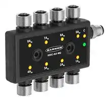
## R95C 8-Port Analog In to Modbus® Hub Instruction Manual

**==> picture [464 x 368] intentionally omitted <==**

Original Instructions p/n: 233568 Rev. C 06-Aug-24 © Banner Engineering Corp. All rights reserved.

## Contents

**Chapter 1 Features** Model............................................................................................................................................................................................................. 3 Overview........................................................................................................................................................................................................ 3 **Chapter 2 Modbus Configuration .......................................................................................... 4 Chapter 3 Mechanical Installation** Wiring............................................................................................................................................................................................................. 8 **Chapter 4 Status Indicators.................................................................................................... 9 Chapter 5 Specifications** FCC Part 15 Class B for Unintentional Radiators........................................................................................................................................ 10 Industry Canada ICES-003(B)......................................................................................................................................................................11 Dimensions...................................................................................................................................................................................................11 **Chapter 6 R95C Accessories................................................................................................ 12 Chapter 7 Banner Engineering Corp Limited Warranty..................................................... 15**

© Banner Engineering Corp. All rights reserved.

R95C 8-Port Analog In To Modbus® Hub Instruction Manual

## Chapter Contents

|Model.................................................................................................................................................................................................................... 3|
|---|
|Overview .............................................................................................................................................................................................................. 3|
|Features<br>Chapter 1|


**==> picture [114 x 59] intentionally omitted <==**

- Compact analog to Modbus® device converter that connects up to eight analog sources and outputs the values

- • Rugged over-molded design meets IP65, IP67, and IP68 • Connects directly to a sensor or anywhere in-line for ease of use • R95C Modbus hubs are a quick, easy, and economical way to integrate non-Modbus devices into a Modbus system

## Model

**==> picture [500 x 64] intentionally omitted <==**

**----- Start of picture text -----**<br>
Model Name Function Control Connectors<br>(8) Integral 4-pin M12 female quick-<br>disconnect connector<br>R95C-8UI-MQ 8-port voltage/current analog input  Modbus®<br>converter<br>(1) Integral 5-pin M12 male quick-<br>disconnect connector<br>**----- End of picture text -----**<br>


## Overview

When an analog input value is received by the R95C-8UI-MQ hub, the numerical representational value is represented via Modbus registers.

## Analog Ranges

Voltage = 0 mV to 11,000 mV Current = 0 µA to 24,000 µA

page 3 of 16

06-Aug-24

© Banner Engineering Corp. All rights reserved.

R95C 8-Port Analog In To Modbus® Hub Instruction Manual

## Chapter Contents

## Chapter 2

## Modbus Configuration

## Analog In Port Type

**==> picture [500 x 88] intentionally omitted <==**

**----- Start of picture text -----**<br>
Modbus Register Address Description I/O Range Comments Default Access Notes<br>[P8|P7|P6|P5|P4|P3|P2|P1]<br>Set to 255 for all ports to be<br>40001 Port Definition 0..255 Voltage = 0, Current = 1 0b11111111 RW current in.<br>Set to 0 for all ports to be<br>voltage in.<br>**----- End of picture text -----**<br>


## Device Port States

**==> picture [500 x 294] intentionally omitted <==**

**----- Start of picture text -----**<br>
Modbus Register Address Description I/O Range Comments Default Access Notes<br>40002 Measurement Value  0..65535 Voltage = mV,  - RO -<br>- Analog In 1 Current = µA<br>40003 Measurement Value  0..65535 Voltage = mV,  - RO -<br>- Analog In 2 Current = µA<br>40004 Measurement Value  0..65535 Voltage = mV,  - RO -<br>- Analog In 3 Current = µA<br>40005 Measurement Value  0..65535 Voltage = mV,  - RO -<br>- Analog In 4 Current = µA<br>40006 Measurement Value  0..65535 Voltage = mV,  - RO -<br>- Analog In 5 Current = µA<br>40007 Measurement Value  0..65535 Voltage = mV,  - RO -<br>- Analog In 6 Current = µA<br>40008 Measurement Value  0..65535 Voltage = mV,  - RO -<br>- Analog In 7 Current = µA<br>40009 Measurement Value  0..65535 Voltage = mV,  - RO -<br>- Analog In 8 Current = µA<br>0b[P8][P7][P6][P5][P4[P3][P2]<br>[P1], where Active for a [P#],<br>signifies that the analog input<br>LED is on, and that the<br>40010 Analog Input Active  0..255 Inactive = 0,  - RO values are between the<br>States Active = 1<br>minimum and maximum<br>setpoints for that port, as<br>defined in registers 40100 to<br>40139<br>**----- End of picture text -----**<br>


## Analog In - Range Setpoints

**==> picture [500 x 128] intentionally omitted <==**

**----- Start of picture text -----**<br>
Modbus Register Address Description I/O Range Comments Default Access Notes<br>Must be less<br>40100 Port 1 - Voltage Minimum LED  0..10999 than the  0 mV RW -<br>maximum<br>setpoint value<br>setpoint.<br>Port 1 - Voltage  Must be greater<br>40101 Maximum LED  0..11000 than the  10000 mV RW<br>setpoint value minimum setpoint. If the value > Max I/O Range,<br>value = Max<br>40102 Port 1 - Voltage  0..500 mV 50mV RW<br>Hysteresis<br>Continued on page 5<br>**----- End of picture text -----**<br>


page 4 of 16

06-Aug-24

© Banner Engineering Corp. All rights reserved.

Modbus Configuration

R95C 8-Port Analog In to Modbus® Hub Instruction Manual

**==> picture [500 x 677] intentionally omitted <==**

**----- Start of picture text -----**<br>
Continued from page 4<br>Modbus Register Address Description I/O Range Comments Default Access Notes<br>Port 1 - Current  Must be less<br>40103 Minimum LED  0..23999 than the  4000 µA RW -<br>setpoint value maximum setpoint.<br>Port 1 - Current  Must be greater<br>40104 Maximum LED  0..24000 than the  20000 µA RW<br>setpoint value minimum setpoint. If the value > Max I/O Range,<br>value = Max<br>Port 1 - Current<br>40105 0..500 µA 100 µA RW<br>Hysteresis<br>Port 2 - Voltage  Must be less<br>40106 Minimum LED  0..10999 than the  0 mV RW -<br>setpoint value maximum setpoint.<br>Port 2 - Voltage  Must be greater<br>40107 Maximum LED  0..11000 than the  10000 mV RW<br>setpoint value minimum setpoint. If the value > Max I/O Range,<br>value = Max<br>40108 Port 2 - Voltage  0..500 mV 50mV RW<br>Hysteresis<br>Port 2 - Current  Must be less<br>40109 Minimum LED  0..23999 than the  4000 µA RW -<br>setpoint value maximum setpoint.<br>Port 2 - Current  Must be greater<br>40110 Maximum LED  0..24000 than the  20000 µA RW<br>setpoint value minimum setpoint. If the value > Max I/O Range,<br>value = Max<br>Port 2 - Current<br>40111 0..500 µA 100 µA RW<br>Hysteresis<br>Port 3 - Voltage  Must be less<br>40112 Minimum LED  0..10999 than the  0 mV RW -<br>setpoint value maximum setpoint.<br>Port 3 - Voltage  Must be greater<br>40113 Maximum LED  0..11000 than the  10000 mV RW<br>setpoint value minimum setpoint. If the value > Max I/O Range,<br>value = Max<br>40114 Port 3 - Voltage  0..500 mV 50mV RW<br>Hysteresis<br>Port 3 -  Must be less<br>40115 CurrentMinimum  0..23999 than the  4000 µA RW -<br>LED setpoint value maximum setpoint.<br>Port 3 - Current  Must be greater<br>40116 Maximum LED  0..24000 than the  20000 µA RW<br>setpoint value minimum setpoint. If the value > Max I/O Range,<br>value = Max<br>Port 3 - Current<br>40117 0..500 µA 100 µA RW<br>Hysteresis<br>Port 4 - Voltage  Must be less<br>40118 Minimum LED  0..10999 than the  0 mV RW -<br>setpoint value maximum setpoint.<br>Port 4 - Voltage  Must be greater<br>40119 Maximum LED  0..11000 than the  10000 mV RW<br>setpoint value minimum setpoint. If the value > Max I/O Range,<br>value = Max<br>40120 Port 4 - Voltage  0..500 mV 50mV RW<br>Hysteresis<br>Port 4 - Current  Must be less<br>40121 Minimum LED  0..23999 than the  4000 µA RW -<br>setpoint value maximum setpoint.<br>Port 4 - Current  Must be greater<br>40122 Maximum LED  0..24000 than the  20000 µA RW<br>setpoint value minimum setpoint. If the value > Max I/O Range,<br>value = Max<br>Port 4 - Current<br>40123 0..500 µA 100 µA RW<br>Hysteresis<br>Port 5 - Voltage  Must be less<br>40124 Minimum LED  0..10999 than the  0 mV RW -<br>setpoint value maximum setpoint.<br>Continued on page 6<br>**----- End of picture text -----**<br>


page 5 of 16

06-Aug-24

© Banner Engineering Corp. All rights reserved.

R95C 8-Port Analog In to Modbus® Hub Instruction Manual

Modbus Configuration

**==> picture [500 x 677] intentionally omitted <==**

**----- Start of picture text -----**<br>
Continued from page 5<br>Modbus Register Address Description I/O Range Comments Default Access Notes<br>Port 5 - Voltage  Must be greater<br>40125 Maximum LED  0..11000 than the  10000 mV RW<br>setpoint value minimum setpoint. If the value > Max I/O Range,<br>value = Max<br>40126 Port 5 - Voltage  0..500 mV 50mV RW<br>Hysteresis<br>Port 5 - Current  Must be less<br>40127 Minimum LED  0..23999 than the  4000 µA RW -<br>setpoint value maximum setpoint.<br>Port 5 - Current  Must be greater<br>40128 Maximum LED  0..24000 than the  20000 µA RW<br>setpoint value minimum setpoint. If the value > Max I/O Range,<br>value = Max<br>Port 5 - Current<br>40129 0..500 µA 100 µA RW<br>Hysteresis<br>Port 6 - Voltage  Must be less<br>40130 Minimum LED  0..10999 than the  0 mV RW -<br>setpoint value maximum setpoint.<br>Port 6 - Voltage  Must be greater<br>40131 Maximum LED  0..11000 than the  10000 mV RW<br>setpoint value minimum setpoint. If the value > Max I/O Range,<br>value = Max<br>40132 Port 6 - Voltage  0..500 mV 50mV RW<br>Hysteresis<br>Port 6 - Current  Must be less<br>40133 Minimum LED  0..23999 than the  4000 µA RW -<br>setpoint value maximum setpoint.<br>Port 6 - Current  Must be greater<br>40134 Maximum LED  0..24000 than the  20000 µA RW<br>setpoint value minimum setpoint. If the value > Max I/O Range,<br>value = Max<br>Port 6 - Current<br>40135 0..500 µA 100 µA RW<br>Hysteresis<br>Port 7 - Voltage  Must be less<br>40136 Minimum LED  0..10999 than the  0 mV RW -<br>setpoint value maximum setpoint.<br>Port 7 - Voltage  Must be greater<br>40137 Maximum LED  0..11000 than the  10000 mV RW<br>setpoint value minimum setpoint. If the value > Max I/O Range,<br>value = Max<br>40138 Port 7 - Voltage  0..500 mV 50mV RW<br>Hysteresis<br>Port 7 - Current  Must be less<br>40139 Minimum LED  0..23999 than the  4000 µA RW -<br>setpoint value maximum setpoint.<br>Port 7 - Current  Must be greater<br>40140 Maximum LED  0..24000 than the  20000 µA RW<br>setpoint value minimum setpoint. If the value > Max I/O Range,<br>value = Max<br>Port 7 - Current<br>40141 0..500 µA 100 µA RW<br>Hysteresis<br>Port 8 - Voltage  Must be less<br>40142 Minimum LED  0..10999 than the  0 mV RW -<br>setpoint value maximum setpoint.<br>Port 8 - Voltage  Must be greater<br>40143 Maximum LED  0..11000 than the  10000 mV RW<br>setpoint value minimum setpoint. If the value > Max I/O Range,<br>value = Max<br>40144 Port 8 - Voltage  0..500 mV 50mV RW<br>Hysteresis<br>Port 8 - Current  Must be less<br>40145 Minimum LED  0..23999 than the  4000 µA RW -<br>setpoint value maximum setpoint.<br>Port 8 - Current  Must be greater<br>40146 Maximum LED  0..24000 than the  20000 µA RW If the value > Max I/O Range, value = Max<br>setpoint value minimum setpoint.<br>Continued on page 7<br>**----- End of picture text -----**<br>


page 6 of 16

06-Aug-24

© Banner Engineering Corp. All rights reserved.

Modbus Configuration

R95C 8-Port Analog In to Modbus® Hub Instruction Manual

**==> picture [500 x 55] intentionally omitted <==**

**----- Start of picture text -----**<br>
Continued from page 6<br>Modbus Register Address Description I/O Range Comments Default Access Notes<br>Port 8 - Current<br>40147 0..500 µA 100 µA RW<br>Hysteresis<br>**----- End of picture text -----**<br>


## ModBus Configuration

**==> picture [500 x 142] intentionally omitted <==**

**----- Start of picture text -----**<br>
Modbus Register Address Description I/O Range Comments Default Access<br>0 = 9.6k 0 = 9600<br>40601 Baud Rate 1 = 19.2k 1 = 19200 1 RW<br>2 = 38.4k 2 = 38400<br>0 = None 0 = None<br>40602 Parity 1 = Odd 1 = Odd 0 RW<br>2 = Even 2 = Even<br>40603 Address 1-257 - 1 RW<br>40604 Reserved None - - -<br>40605 Restore Factory  0 = No Operation, 1 =  - - WO<br>Configuration Restore<br>**----- End of picture text -----**<br>


## Device Information

**==> picture [500 x 262] intentionally omitted <==**

**----- Start of picture text -----**<br>
Modbus<br>Register  Description I/O Range Comments Default Access Notes<br>Address<br>40606-40615 Banner Name 0..65535 - Banner Engineering RO (9 words/18 characters)<br>40616-40631 Product Name 0..65535 - R95C-8UI-MQ RO (16 words/32 characters)<br>40632 Item H 0..65535 814472 split into  12 RO Banner Item Number<br>two 16-bit<br>40633 Item L 0..65535 registers 28040 RO -<br>40634 Serial Number H 0..65535 - - RO<br>40635 Serial Number 0..65535 - - RO<br>Serial Number is split into four<br>40636 Serial Number 0..65535 - - RO 16-bit registers<br>40637 Serial Number L 0..65535 - - RO<br>User writable  More Sensors. More<br>40644-40659 User Define Tag 0..65535 space Solutions. RW (16 words/32 characters)<br>40680 Discovery 0..1 0 = Disabled, 1 = Enabled - RW Flash all LEDs to find hub<br>40681 All-Time Run Time H 0..65535 - - RO Upper 16 of 32 bits<br>40682 All-Time Run Time L 0..65535 - - RO Lower 16 of 32 bits<br>40683 Resettable Run Time H 0..65535 - - RW Upper 16 of 32 bits<br>40684 Resettable Run Time L 0..65535 - - RW Lower 16 of 32 bits<br>**----- End of picture text -----**<br>


page 7 of 16

06-Aug-24

© Banner Engineering Corp. All rights reserved.

R95C 8-Port Analog In To Modbus® Hub Instruction Manual

## Chapter Contents

Wiring ................................................................................................................................................................................................................... 8

## Chapter 3 Mechanical Installation

Install the R95C to allow access for functional checks, maintenance, and service or replacement. Do not install the R95C in such a way to allow for intentional defeat.

Fasteners must be of sufficient strength to guard against breakage. The use of permanent fasteners or locking hardware is recommended to prevent the loosening or displacement of the device. The mounting hole (4.5 mm) in the R95C accepts M4 (#8) hardware.

See the figure below to help in determining the minimum screw length.

**==> picture [89 x 46] intentionally omitted <==**

**----- Start of picture text -----**<br>
MOUNTING SCREW<br>17.0 mm<br>**----- End of picture text -----**<br>


CAUTION: Do not overtighten the R95C's mounting screw during installation. Overtightening can affect the performance of the R95C.

## Wiring

**==> picture [379 x 169] intentionally omitted <==**

**----- Start of picture text -----**<br>
Port 1-Port 8 — Female Pin Signal Description<br>1 12 V DC to 30 V DC<br>2<br>1 2 Analog In<br>3 3 Ground<br>4<br>4 Not Used<br>Male Pin Signal Description<br>1 12 V DC to 30 V DC<br>1<br>2 RS485/D1/B/+<br>2 fs<br>4 3 Ground<br>S) 4 RS485/D0/A/-<br>3 5<br>5 Banner 1-wire<br>**----- End of picture text -----**<br>


page 8 of 16

06-Aug-24

© Banner Engineering Corp. All rights reserved.

R95C 8-Port Analog In To Modbus® Hub Instruction Manual

## Chapter Contents

## Chapter 4

## Status Indicators

The R95C 8-Port Analog In to Modbus® Hub has matching amber LED indicators on both sides for each analog in port to allow for installation needs and still provide adequate indication visibility. There is also an additional amber LED indicator on both sides of the converter, which is specific to the Modbus communication.

**==> picture [251 x 87] intentionally omitted <==**

**----- Start of picture text -----**<br>
Com LED<br>(x1 near M12 male)<br>8AIN 7AIN 6AIN 5AIN C<br>Power LED<br>4AIN 3AIN 2AIN 1AIN (x1 near M12 male)<br>Analog In LEDs<br>(x8)<br>**----- End of picture text -----**<br>


## Power Indicator Green LED

**==> picture [500 x 44] intentionally omitted <==**

**----- Start of picture text -----**<br>
Indication Status<br>Off Power off<br>Solid Green Power on<br>**----- End of picture text -----**<br>


## Modbus Communication Amber LED

**==> picture [500 x 72] intentionally omitted <==**

**----- Start of picture text -----**<br>
Indication Status<br>Off Modbus communications are not present<br>Flashing Amber (4 Hz) Modbus communications are active<br>Solid Amber for 2 Seconds, Then to Off Modbus communications are lost after connection<br>Solid Amber for 2 Seconds, Then to Flashing Amber (4 Hz) Modbus communications momentarily lost, but then communication was reestablished<br>**----- End of picture text -----**<br>


## Analog In Amber LED

**==> picture [500 x 89] intentionally omitted <==**

**----- Start of picture text -----**<br>
Indication Status<br>Off Analog current value is less than the minimum setpoint OR analog value is greater than the<br>maximum setpoint<br>Solid Amber Analog current value is between the minimum and maximum setpoints<br>Default Current Values: Default Voltage Values:<br>• Minimum = 0.004 A • Minimum = 0 V<br>• Maximum = 0.02 A • Maximum = 10 V<br>**----- End of picture text -----**<br>


page 9 of 16

06-Aug-24

© Banner Engineering Corp. All rights reserved.

R95C 8-Port Analog In To Modbus® Hub Instruction Manual

## Chapter Contents

FCC Part 15 Class B for Unintentional Radiators .............................................................................................................................................. 10 Industry Canada ICES-003(B).............................................................................................................................................................................11 Dimensions..........................................................................................................................................................................................................11

## Chapter 5

## Specifications

Supply Voltage

Product Identification

12 V DC to 30 V DC at 400 mA maximum

Power Pass-Through Current 500 mA per port maximum

Analog Input Impedance Current version: Approximately 250 ohms Voltage version: Approximately 14.3K ohms

Supply Protection Circuitry Protected against reverse polarity and transient voltages

Leakage Current Immunity 400 µA

Indicators Green: Power Amber: Modbus communications Amber: Analog In status

Connections

Environmental Rating IP65, IP67, IP68 UL Type 1 Operating Conditions Temperature: –40 °C to +70 °C (–40 °F to +158 °F) 90% at +70 °C maximum relative humidity (non-condensing) Storage Temperature: –40 °C to +80 °C (–40 °F to +176 °F) Required Overcurrent Protection

WARNING: Electrical connections must be made by qualified personnel in accordance with local and national electrical codes and regulations.

(8) Integral 4-pin M12 female quick-disconnect connectors

(1) Integral 5-pin M12 male quick-disconnect connector

Construction Coupling Material: Nickel-plated brass Connector Body: PVC translucent black

## Vibration and Mechanical Shock

Meets IEC 60068-2-6 requirements (Vibration: 10 Hz to 55 Hz, 0.5 mm amplitude, 5 minutes sweep, 30 minutes dwell) Meets IEC 60068-2-27 requirements (Shock: 15G 11 ms duration, half sine wave)

Certifications

Banner Engineering BV Park Lane, Culliganlaan 2F bus 3 1831 Diegem, BELGIUM Turck Banner LTD Blenheim House Blenheim Court Wickford, Essex SS11 8YT GREAT BRITAIN

Overcurrent protection is required to be provided by end product application per the supplied table.

Overcurrent protection may be provided with external fusing or via Current Limiting, Class 2 Power Supply. Supply wiring leads < 24 AWG shall not be spliced. For additional product support, go

to www.bannerengineering.com.

**==> picture [208 x 68] intentionally omitted <==**

**----- Start of picture text -----**<br>
Supply  Supply<br>Required Overcurrent  Required Overcurrent<br>Wiring  Wiring<br>Protection (A) Protection (A)<br>(AWG) (AWG)<br>20 5.0 26 1.0<br>22 3.0 28 0.8<br>24 1.0 30 0.5<br>**----- End of picture text -----**<br>


## FCC Part 15 Class B for Unintentional Radiators

(Part 15.105(b)) This equipment has been tested and found to comply with the limits for a Class B digital device, pursuant to part 15 of the FCC Rules. These limits are designed to provide reasonable protection against harmful interference in a residential installation. This equipment generates, uses, and can radiate radio frequency energy and, if not installed and used in accordance with the instructions, may cause harmful interference to radio communications. However, there is no guarantee that interference will not occur in a particular installation. If this equipment does cause harmful interference to radio or television reception, which can be determined by turning the equipment off and on, the user is encouraged to try to correct the interference by one or more of the following measures:

- Reorient or relocate the receiving antenna.

- Increase the separation between the equipment and receiver.

- Connect the equipment into an outlet on a circuit different from that to which the receiver is connected.

- • Consult the dealer or an experienced radio/TV technician for help.

(Part 15.21) Any changes or modifications not expressly approved by the party responsible for compliance could void the user’s authority to operate this equipment.

page 10 of 16

06-Aug-24

© Banner Engineering Corp. All rights reserved.

Specifications

R95C 8-Port Analog In to Modbus® Hub Instruction Manual

## Industry Canada ICES-003(B)

This device complies with CAN ICES-3 (B)/NMB-3(B). Operation is subject to the following two conditions: 1) This device may not cause harmful interference; and 2) This device must accept any interference received, including interference that may cause undesired operation.

Cet appareil est conforme à la norme NMB-3(B). Le fonctionnement est soumis aux deux conditions suivantes : (1) ce dispositif ne peut pas occasionner d'interférences, et (2) il doit tolérer toute interférence, y compris celles susceptibles de provoquer un fonctionnement non souhaité du dispositif.

## Dimensions

All measurements are listed in millimeters [inches], unless noted otherwise. The measurements provided are subject to change.

page 11 of 16

06-Aug-24

© Banner Engineering Corp. All rights reserved.

R95C 8-Port Analog In To Modbus® Hub Instruction Manual

## Chapter Contents

## Chapter 6

## R95C Accessories

## Cordsets

**==> picture [500 x 293] intentionally omitted <==**

**----- Start of picture text -----**<br>
4-pin Double-Ended M12 Female to M12 Male Right-Angle Cordsets<br>Model Length Dimensions (mm) Pinouts<br>BC-M12F4-M12M4A-22-1 1 m (3.28 ft) Female<br>32 Typ. 2<br>BC-M12F4-M12M4A-22-2 2 m (6.56 ft) [1.26"] 1<br>BC-M12F4-M12M4A-22-5 5 m (16.4 ft) 30 Typ.[1.18"] 4 3 1 = Brown<br>BC-M12F4-M12M4A-22-8 8 m (26.25 ft) ø 14.5 [0.57"]M12 x 1 Male 2 = White 3 = Blue<br>BC-M12F4-M12M4A-22-10 10 m (30.81 ft) 4 = Black<br>ø 14.5 [0.57"] 1<br>44 Typ. M12 x 1 2<br>BC-M12F4-M12M4A-22-15 15 m (49.2 ft) [1.73"] 4<br>3<br>4-pin Double-Ended M12 Female Right-Angle to M12 Male Right-Angle Cordsets<br>Model Length Dimensions (mm) Pinouts<br>BC-M12F4A-M12M4A-22-1 1 m (3.28 ft) Female<br>BC-M12F4A-M12M4A-22-2 2 m (6.56 ft) 32 Typ.[1.26"] 1 2<br>BC-M12F4A-M12M4A-22-5 5 m (16.4 ft) 30 Typ. 4 3<br>[1.18"] 1 = Brown<br>BC-M12F4A-M12M4A-22-8 8 m (26.25 ft) 2 = White<br>M12 x 1 Male 3 = Blue<br>BC-M12F4A-M12M4A-22-10 10 m (30.81 ft) ø 14.5 [0.57"] 31 Typ. 4 = Black<br>1<br>2<br>BC-M12F4A-M12M4A-22-15 15 m (49.2 ft) 32 Typ. 4<br>3<br>**----- End of picture text -----**<br>


## Splitter Cordsets

**==> picture [500 x 201] intentionally omitted <==**

**----- Start of picture text -----**<br>
5-Pin Double-Ended M12 Female to M12 Male Flat Junction Splitter Cordsets<br>Model  Description Pinout (Male)  Pinout (Female)<br>Four (no cable) 5-pin M12 female quick-disconnect  1<br>connectors 2<br>2 1<br>CSB4-M1251M1250 One 0.3 m (0.98 ft) cable with a 5-pin M12 male  4 3<br>quick-disconnect connector 3 5 4 5<br>Parallel wiring<br>Branch 1<br>2 x 19 Branch 2 1 = Brown 1 = Brown<br>72 mm Branch 3 2 = White3 = Blue 2 = White3 = Blue<br>3 x 18 4 = Black 4 = Black<br>Branch 4 5 = Gray 5 = Gray<br>32 mm Male TrunkLength<br>**----- End of picture text -----**<br>


page 12 of 16

06-Aug-24

© Banner Engineering Corp. All rights reserved.

R95C Accessories

R95C 8-Port Analog In to Modbus® Hub Instruction Manual

**==> picture [482 x 99] intentionally omitted <==**

**----- Start of picture text -----**<br>
4-Pin M12 Female RS-485 to USB Adapter Cordset, with Wall Plug<br>Model  Length  Style  Dimensions  Pinout (Female)<br>2 4<br>1 3<br>BWA-UCT-900 1 m (3.28 ft)  Straight<br>1 = Brown<br>2 = White<br>3 = Blue<br>4 = Black<br>**----- End of picture text -----**<br>


## Splitter Tee

**==> picture [463 x 129] intentionally omitted <==**

**----- Start of picture text -----**<br>
5-Pin M12 Female to M12 Male Splitter Tee<br>Model  Pinout (Male)  Pinout (Female)<br>CSB-M1250M1250-T 1 2<br>• Two 5-pin M12 female  2 1<br>quick-disconnect  4 3<br>connectors re 3 © 5 4 5<br>• One 5-pin M12 male<br>quick-disconnect  @ 1 = Brown 2 = White  1 = Brown  eur<br>connector 3 = Blue  2 = White<br>• Parallel wiring 4 = Black  3 = Blue 4 = Black<br>5 = Gray<br>5 = Gray<br>**----- End of picture text -----**<br>


## 5-Pin Molded Junction Blocks

**==> picture [474 x 141] intentionally omitted <==**

**----- Start of picture text -----**<br>
Model Pinout (Male) Pinout (Female)<br>R50-4M125-M125Q-P  Molded Junction Block<br>• Four integral 5-pin M12 female quick-<br>disconnect connectors<br>• One integral 5-pin M12 male quick-<br>1 2<br>disconnect connector<br>• Parallel wiring 2 RB 1<br>• Product documentation (p/n 227974) 4 3<br>3 5 4 5<br>R95-8M125-M125Q-P  Molded Junction Block 1 = Brown 1 = Brown<br>• Eight integral 5-pin M12 female quick- 2 = White3 = Blue 2 = White3 = Blue<br>disconnect connectors 4 = Black 4 = Black<br>• One integral 5-pin M12 male quick- 5 = Gray 5 = Gray<br>**----- End of picture text -----**<br>


- One integral 5-pin M12 male quickdisconnect connector

- • Parallel wiring • Product documentation (p/n 227974)

## Brackets

- 8.6 B

- • Stainless steel bracket • 4x M4-07 pemnuts (B) • Includes 2x M4 stainless steel hex head screws and flat washers 74 A “|

- Hole center spacing: A = 40, B = 20 o|J& Hole size: A = ø 5 24 10.1 ae

## SMBR90S

page 13 of 16

06-Aug-24

© Banner Engineering Corp. All rights reserved.

R95C 8-Port Analog In to Modbus® Hub Instruction Manual

R95C Accessories

## SMBR95RA

- Stainless steel right-angle bracket

- • M4 x 0.7 mm #316SS screws (qty 2)

**==> picture [68 x 48] intentionally omitted <==**

**----- Start of picture text -----**<br>
90<br>2X M4 x  40<br>0.7 PEM<br>Ø4.5<br>2X Ø4.5 40<br>**----- End of picture text -----**<br>


page 14 of 16

06-Aug-24

© Banner Engineering Corp. All rights reserved.

R95C 8-Port Analog In To Modbus® Hub Instruction Manual

## Chapter Contents

## Chapter 7

## Banner Engineering Corp Limited Warranty

Banner Engineering Corp. warrants its products to be free from defects in material and workmanship for one year following the date of shipment. Banner Engineering Corp. will repair or replace, free of charge, any product of its manufacture which, at the time it is returned to the factory, is found to have been defective during the warranty period. This warranty does not cover damage or liability for misuse, abuse, or the improper application or installation of the Banner product.

THIS LIMITED WARRANTY IS EXCLUSIVE AND IN LIEU OF ALL OTHER WARRANTIES WHETHER EXPRESS OR IMPLIED (INCLUDING, WITHOUT LIMITATION, ANY WARRANTY OF MERCHANTABILITY OR FITNESS FOR A PARTICULAR PURPOSE), AND WHETHER ARISING UNDER COURSE OF PERFORMANCE, COURSE OF DEALING OR TRADE USAGE.

This Warranty is exclusive and limited to repair or, at the discretion of Banner Engineering Corp., replacement. IN NO EVENT SHALL BANNER ENGINEERING CORP. BE LIABLE TO BUYER OR ANY OTHER PERSON OR ENTITY FOR ANY EXTRA COSTS, EXPENSES, LOSSES, LOSS OF PROFITS, OR ANY INCIDENTAL, CONSEQUENTIAL OR SPECIAL DAMAGES RESULTING FROM ANY PRODUCT DEFECT OR FROM THE USE OR INABILITY TO USE THE PRODUCT, WHETHER ARISING IN CONTRACT OR WARRANTY, STATUTE, TORT, STRICT LIABILITY, NEGLIGENCE, OR OTHERWISE.

Banner Engineering Corp. reserves the right to change, modify or improve the design of the product without assuming any obligations or liabilities relating to any product previously manufactured by Banner Engineering Corp. Any misuse, abuse, or improper application or installation of this product or use of the product for personal protection applications when the product is identified as not intended for such purposes will void the product warranty. Any modifications to this product without prior express approval by Banner Engineering Corp will void the product warranties. All specifications published in this document are subject to change; Banner reserves the right to modify product specifications or update documentation at any time. Specifications and product information in English supersede that which is provided in any other language. For the most recent version of any documentation, refer to: www.bannerengineering.com.

For patent information, see www.bannerengineering.com/patents.

page 15 of 16

06-Aug-24

© Banner Engineering Corp. All rights reserved.

## LinkedIn

Twitter

Facebook

© 2024. All rights reserved. www.bannerengineering.com
Updated at April 23, 2026
Founded in 1966, Banner Engineering is a globally recognized leader in the design and manufacture of industrial automation products. The company is renowned for developing innovative, high-quality solutions that improve operational efficiency, safeguard personnel, and optimize manufacturing processes across a diverse range of industries. Our extensive selection of Banner Engineering components prominently features their industry-leading sensing technologies. We offer a comprehensive array of precision light sensors engineered for accurate detection and measurement in demanding environments. Complementing this core sensing portfolio is a robust offering of automation signaling devices, including visual signal indicator units and essential accessories, which provide clear and immediate communication of machine status. Beyond primary sensing and indication solutions, our range encompasses critical components for broader process control and machine safety. This includes advanced process controllers, reliable pressure sensors and transducers, and dependable safety relays. Supported by a variety of purpose-built sensor accessories and fiber optic lead assemblies, Banner Engineering delivers the durable, high-performance technologies required to build and maintain sophisticated automated systems.
About Novapart
Novapart is a B2B electronic component broker specialising in stock shortages and cost reduction. We source hard-to-find parts and identify compliant alternatives across a catalogue of 410,000+ components from 500+ manufacturers.
Learn more →Stock Shortage Specialist
When a component is unavailable, discontinued or has an unacceptable lead time, we tap into our network of vetted European and Asian distributors to source what you need — without compromising on quality or traceability.
Request a quote →Compliant Alternatives
We identify pin-to-pin, electrically equivalent substitutes that meet the same certifications (RoHS, AEC-Q100, REACH) as your original specification — validated against datasheets, not just part numbers. Often at a lower cost.
BOM Analysis service →