


R95C-8UI-KQ
Signal Converter, Current, Voltage, PFM, 1 Channels, 30 VDC
- Manufacturer: BANNER ENGINEERING
- Product type: Signal Converters
- SVHC: No SVHC (15-Jan-2018)
- Accuracy %: -
- Product Range: R95C Series
- Supply Voltage: 30VDC
- Isolation Input: -
- No. of Channels: 8 Channel
- Output Accuracy: -
- No. of Output Channels: 1Channels
- Signal Conditioner Input: Current, Voltage
- Signal Conditioner Output: PFM
- Signal Conditioner Mounting: Screw Mount
| Delivery and price | |
|---|---|
| Units per pack | 1 |
| Price | 305.84 € |
| Current stock | 10+ |
| Lead time | 30 days |
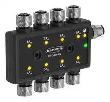
R95C 8-Port Analog In to IO-Link Hub Instruction Manual

## Features

**==> picture [114 x 59] intentionally omitted <==**

- Compact analog to IO-Link device converter that connects to an analog source and outputs the value to the IO-Link master

- • Ability to represent one of the eight analog inputs as a PFM output • Rugged over-molded design meets IP65, IP67, and IP68 • Connects directly to a sensor or anywhere in-line for ease of use • R95C IO-Link hubs are a quick, easy, and economical way to integrate non-IOLink devices into an IO-Link system

## Models

**==> picture [336 x 80] intentionally omitted <==**

**----- Start of picture text -----**<br>
Housing Function Converter Control Connector<br>R95 C 8UI K Q<br>C = Converter 8UI = 8-port, K = IO-Link Q = M12 integral<br>voltage/current quick disconnect<br>analog input<br>**----- End of picture text -----**<br>


## Overview

When an analog input value is received by the R95C-8UI-KQ hub, the numerical representational value is sent to an IO-Link Master via Process Data In (PDI).

PDI Analog Ranges PFM Input Source Channel Voltage = 0 mV to 10,000 mV Selects the analog input value from Port 1..8 as the PFM outCurrent = 4,000 µA to 20,000 µA put source PFM Out Pulse Frequency Configuration Enables a PFM representation of an analog input as an output Sets the near and far frequency values

## Configuration

For more information, see P/N 232874 R95C-8UI-KQ IO-Link Data Reference Guide and P/N 232873 R95C-8UI-KQ IODD Files.

## IO-Link®

IO-Link® is a point-to-point communication link between a master device and a sensor and/or light. It can be used to automatically parameterize sensors or lights and to transmit process data. For the latest IO-Link protocol and specifications, please visit www.io-link.com.

For the latest IODD files, please refer to the Banner Engineering Corp website at: www.bannerengineering.com.

## Mechanical Installation

Install the R95C to allow access for functional checks, maintenance, and service or replacement. Do not install the R95C in such a way to allow for intentional defeat.

Fasteners must be of sufficient strength to guard against breakage. The use of permanent fasteners or locking hardware is recommended to prevent the loosening or displacement of the device. The mounting hole (4.5 mm) in the R95C accepts M4 (#8) hardware.

See the figure below to help in determining the minimum screw length.

**==> picture [39 x 40] intentionally omitted <==**

**==> picture [91 x 47] intentionally omitted <==**

**----- Start of picture text -----**<br>
MOUNTING SCREW<br>17.0 mm<br>**----- End of picture text -----**<br>


Original Instructions July 25, 2023

© Banner Engineering Corp.

p/n: 232750 Rev. A

232750

R95C 8-Port Analog In to IO-Link Hub Instruction Manual

**==> picture [32 x 38] intentionally omitted <==**

CAUTION: Do not overtighten the R95C's mounting screw during installation. Overtightening can affect the performance of the R95C.

## Wiring

**==> picture [500 x 175] intentionally omitted <==**

**----- Start of picture text -----**<br>
Port 1-Port 8 — Female  Pin  Signal Description<br>1  18 V DC to 30 V DC<br>2 2  Analog In<br>1<br>3  Ground<br>3<br>4 4  Not Used<br>Male  Pin  Signal Description<br>1 1  18 V DC to 30 V DC<br>2 2  Banner-specific/PFM out<br>4 3  Ground<br>3 4  IO-Link<br>**----- End of picture text -----**<br>


## Status Indicators

The R95C 8-Port Analog In to IO-Link Hub has matching amber LED indicators on both sides for each analog in port to allow for installation needs and still provide adequate indication visibility. There is also an additional amber LED indicator on both sides of the converter, which is specific to the IO-Link communication.

**==> picture [251 x 87] intentionally omitted <==**

**----- Start of picture text -----**<br>
Com LED<br>(x1 near M12 male)<br>8AIN 7AIN 6AIN 5AIN<br>Power LED<br>4AIN 3AIN 2AIN 1AIN (x1 near M12 male)<br>Analog In LEDs<br>(x8)<br>**----- End of picture text -----**<br>


**==> picture [500 x 206] intentionally omitted <==**

**----- Start of picture text -----**<br>
Power Indicator Green LED<br>Indication  Status<br>Off  Power off<br>Solid Green  Power on<br>IO-Link Amber LED<br>Indication  Status<br>Off  IO-Link communications are not present<br>Flashing Amber (900 ms On, 100 ms Off)  IO-Link communications are active<br>Analog In Amber LED<br>Indication  Status<br>Off  Analog current value is less than setpoint SP1 OR analog value is greater than setpoint SP2<br>Solid Amber  Analog current value is between setpoint SP1 AND setpoint SP2<br>Default Current Values: Default Voltage Values:<br>• SP1 = 0.004 A  • SP1 = 0 V<br>• SP2 = 0.02 A  • SP2 = 10 V<br>**----- End of picture text -----**<br>


page 2

July 25, 2023

© Banner Engineering Corp.

R95C 8-Port Analog In to IO-Link Hub Instruction Manual

## Specifications

Supply Voltage

## Product Identification

18 V DC to 30 V DC at 400 mA maximum

Power Pass-Through Current 500 mA per port maximum

Analog Input Impedance Current version: Approximately 450 ohms Voltage version: Approximately 14.3K ohms

Supply Protection Circuitry Protected against reverse polarity and transient voltages

Leakage Current Immunity 400 µA

## Indicators

Green: Power Amber: IO-Link communications Amber: Analog In status

## Connections

(8) Integral 4-pin M12 female quick-disconnect connector

(1) Integral 4-pin M12 male quick-disconnect connector Construction Coupling Material: Nickel-plated brass Connector Body: PVC translucent black

## Vibration and Mechanical Shock

Meets IEC 60068-2-6 requirements (Vibration: 10 Hz to 55 Hz, 0.5 mm amplitude, 5 minutes sweep, 30 minutes dwell) Meets IEC 60068-2-27 requirements (Shock: 15G 11 ms duration, half sine wave)

Certifications

Banner Engineering BV Park Lane, Culliganlaan 2F bus 3 1831 Diegem, BELGIUM

## Environmental Rating

IP65, IP67, IP68 NEMA/UL Type 1

Operating Conditions

Temperature: –40 °C to +70 °C (–40 °F to +158 °F) 90% at +70 °C maximum relative humidity (non-condensing) Storage Temperature: –40 °C to +80 °C (–40 °F to +176 °F)

Required Overcurrent Protection

WARNING: Electrical connections must be made by qualified personnel in accordance with local and national electrical codes and regulations.

Overcurrent protection is required to be provided by end product application per the supplied table.

Overcurrent protection may be provided with external fusing or via Current Limiting, Class 2 Power Supply. Supply wiring leads < 24 AWG shall not be spliced. For additional product support, go

to www.bannerengineering.com.

|Supply<br>Wiring<br>(AWG)|Supply<br>Wiring<br>(AWG)|Required Overcurrent<br>Protection (A)|Required Overcurrent<br>Protection (A)|Supply<br>Wiring<br>(AWG)|Required Overcurrent<br>Protection (A)|Required Overcurrent<br>Protection (A)|
|---|---|---|---|---|---|---|
||20<br>22|5.0<br>3.0||26<br>28|1.0<br>0.8||
||24|1.0||30|0.5||


## FCC Part 15 Class B

This equipment has been tested and found to comply with the limits for a Class B digital device, pursuant to part 15 of the FCC Rules. These limits are designed to provide reasonable protection against harmful interference in a residential installation. This equipment generates, uses and can radiate radio frequency energy and, if not installed and used in accordance with the instructions, may cause harmful interference to radio communications. However, there is no guarantee that interference will not occur in a particular installation. If this equipment does cause harmful interference to radio or television reception, which can be determined by turning the equipment off and on, the user is encouraged to try to correct the interference by one or more of the following measures:

- Reorient or relocate the receiving antenna.

- Increase the separation between the equipment and receiver.

- Connect the equipment into an outlet on a circuit different from that to which the receiver is connected.

- Consult the dealer or an experienced radio/TV technician for help.

## Industry Canada ICES-003(B)

This device complies with CAN ICES-3 (B)/NMB-3(B). Operation is subject to the following two conditions: 1) This device may not cause harmful interference; and 2) This device must accept any interference received, including interference that may cause undesired operation.

Cet appareil est conforme à la norme NMB-3(B). Le fonctionnement est soumis aux deux conditions suivantes : (1) ce dispositif ne peut pas occasionner d'interférences, et (2) il doit tolérer toute interférence, y compris celles susceptibles de provoquer un fonctionnement non souhaité du dispositif.

July 25, 2023

page 3

© Banner Engineering Corp.

R95C 8-Port Analog In to IO-Link Hub Instruction Manual

## Dimensions

All measurements are listed in millimeters [inches], unless noted otherwise.

July 25, 2023

page 4

© Banner Engineering Corp.

R95C 8-Port Analog In to IO-Link Hub Instruction Manual

## Accessories

## Cordsets

**==> picture [500 x 198] intentionally omitted <==**

**----- Start of picture text -----**<br>
4-Pin Threaded M12 Cordsets—Double Ended<br>Model  Length  Style  Dimensions  Pinout<br>MQDEC-401SS  0.31 m (1 ft)   Female<br>MQDEC-403SS 0.91 m (2.99 ft)<br>2<br>40 Typ.<br>MQDEC-406SS 1.83 m (6 ft)  [1.58"] 1<br>MQDEC-412SS  3.66 m (12 ft)  4 3<br>MQDEC-420SS  6.10 m (20 ft)  M12 x 1<br>MQDEC-430SS  9.14 m (30.2 ft)  Male Straight/Female  ø 14.5 [0.57"] Male<br>Straight  44 Typ.<br>[1.73"] 1<br>2<br>4<br>MQDEC-450SS  15.2 m (49.9 ft)  M12 x 1 3<br>ø 14.5 [0.57"] 1 = Brown<br>2 = White<br>3 = Blue<br>4 = Black<br>**----- End of picture text -----**<br>


## Banner Engineering Corp Limited Warranty

Banner Engineering Corp. warrants its products to be free from defects in material and workmanship for one year following the date of shipment. Banner Engineering Corp. will repair or replace, free of charge, any product of its manufacture which, at the time it is returned to the factory, is found to have been defective during the warranty period. This warranty does not cover damage or liability for misuse, abuse, or the improper application or installation of the Banner product.

THIS LIMITED WARRANTY IS EXCLUSIVE AND IN LIEU OF ALL OTHER WARRANTIES WHETHER EXPRESS OR IMPLIED (INCLUDING, WITHOUT LIMITATION, ANY WARRANTY OF MERCHANTABILITY OR FITNESS FOR A PARTICULAR PURPOSE), AND WHETHER ARISING UNDER COURSE OF PERFORMANCE, COURSE OF DEALING OR TRADE USAGE.

This Warranty is exclusive and limited to repair or, at the discretion of Banner Engineering Corp., replacement. IN NO EVENT SHALL BANNER ENGINEERING CORP. BE LIABLE TO BUYER OR ANY OTHER PERSON OR ENTITY FOR ANY EXTRA COSTS, EXPENSES, LOSSES, LOSS OF PROFITS, OR ANY INCIDENTAL, CONSEQUENTIAL OR SPECIAL DAMAGES RESULTING FROM ANY PRODUCT DEFECT OR FROM THE USE OR INABILITY TO USE THE PRODUCT, WHETHER ARISING IN CONTRACT OR WARRANTY, STATUTE, TORT, STRICT LIABILITY, NEGLIGENCE, OR OTHERWISE.

Banner Engineering Corp. reserves the right to change, modify or improve the design of the product without assuming any obligations or liabilities relating to any product previously manufactured by Banner Engineering Corp. Any misuse, abuse, or improper application or installation of this product or use of the product for personal protection applications when the product is identified as not intended for such purposes will void the product warranty. Any modifications to this product without prior express approval by Banner Engineering Corp will void the product warranties. All specifications published in this document are subject to change; Banner reserves the right to modify product specifications or update documentation at any time. Specifications and product information in English supersede that which is provided in any other language. For the most recent version of any documentation, refer to: www.bannerengineering.com.

For patent information, see www.bannerengineering.com/patents.

July 25, 2023

page 5

© Banner Engineering Corp.
Updated at April 23, 2026
Founded in 1966, Banner Engineering is a globally recognized leader in the design and manufacture of industrial automation products. The company is renowned for developing innovative, high-quality solutions that improve operational efficiency, safeguard personnel, and optimize manufacturing processes across a diverse range of industries. Our extensive selection of Banner Engineering components prominently features their industry-leading sensing technologies. We offer a comprehensive array of precision light sensors engineered for accurate detection and measurement in demanding environments. Complementing this core sensing portfolio is a robust offering of automation signaling devices, including visual signal indicator units and essential accessories, which provide clear and immediate communication of machine status. Beyond primary sensing and indication solutions, our range encompasses critical components for broader process control and machine safety. This includes advanced process controllers, reliable pressure sensors and transducers, and dependable safety relays. Supported by a variety of purpose-built sensor accessories and fiber optic lead assemblies, Banner Engineering delivers the durable, high-performance technologies required to build and maintain sophisticated automated systems.
About Novapart
Novapart is a B2B electronic component broker specialising in stock shortages and cost reduction. We source hard-to-find parts and identify compliant alternatives across a catalogue of 410,000+ components from 500+ manufacturers.
Learn more →Stock Shortage Specialist
When a component is unavailable, discontinued or has an unacceptable lead time, we tap into our network of vetted European and Asian distributors to source what you need — without compromising on quality or traceability.
Request a quote →Compliant Alternatives
We identify pin-to-pin, electrically equivalent substitutes that meet the same certifications (RoHS, AEC-Q100, REACH) as your original specification — validated against datasheets, not just part numbers. Often at a lower cost.
BOM Analysis service →