
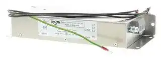


R88A-FIK304-RE
Filter, Accurax G5 Servo Motors, 400 V, 3 Phase
- Manufacturer: OMRON INDUSTRIAL AUTOMATION
- Product type: Controller Accessories
- Current Rating:4A; Product Range:Accurax G5 Series; SVHC:No SVHC (17-Dec-2015)
- SVHC: No SVHC (17-Dec-2015)
- Product Range: Accurax G5
- Current Rating: 4A
| Delivery and price | |
|---|---|
| Units per pack | 1 |
| Price | 87.02 € |
| Current stock | 10+ |
| Lead time | 30 days |
## **R88D-KN** @@@-ECT, R88D-KN@@@-ML2, R88D-KT@ ## **Accurax G5 servo drive** **Accurate motion control in a compact size servo drive family. EtherCAT and safety builtin.** - EtherCAT, ML-II and Analog/ Pulse servo drive models - Safety conforming ISO13849-1 PL-d - High-response frequency of 2 kHz - High resolution provided by 20 bits encoder - Drive Programming: embedded indexer functionality in the Analogue/ Pulse models - External encoder input for full closed loop - Real time auto-tuning - Advanced tuning algorithms (Anti-vibration function, torque feedforward, disturbance observer) ## **Ratings** - 230 VAC Single-phase 100 W to 1.5 kW (8.59 Nm) • 400 VAC three-phase 600 W to 15 kW (95.5 Nm) **==> picture [511 x 419] intentionally omitted <==** **----- Start of picture text -----**<br> Ld System configuration<br>EtherCAT control<br>as EtherCAT controllers<br>|| Je l [7 Personal computersoftware: CX-One<br>CJ PLC series:<br>CJ1W-NC EtherCAT unit<br>ae| 2 1 5 |<br>Poo Trajexia stand-alone with EtherCAT<br>ADR ADR ADR ADR ADR<br>Up to 100 m<br>af EtherCAT. — af af ap —————————~ au<br>Accurax G5 Accurax G5 Accurax G5 Accurax G5 Accurax G5<br>Servo Drive Servo Drive Servo Drive Servo Drive Servo Drive<br>|<br>Power cable Encoder cable Open Analog/pulse control<br>N<br> Accurax G5 Analog/pulse<br> Servo Drive<br>Servo Motor<br>3000 rpm (50 W - 750 kW)<br>Personal computer:<br>Software CX-One<br>fi--sc-e----<br>Motion control unit<br>Servo Motor Power cable Position control unit<br>3000 rpm (750 W - 5 kW)<br>2000 rpm (400 W - 5 kW) [s $ ——-e—— Hl | S s<br>1000 rpm (900 W - 3 kW) General purpose cable<br>Encoder cable<br> R88D-KT Terminal block<br>“ for Servo drive I/O<br>general purpose<br>signals<br>Unit<br>Servo Motor<br>1500 rpm (7.5 kW - 15 kW)<br>1000 rpm (4.5 kW - 6kW)<br>**----- End of picture text -----**<br> **Accurax G5 servo drive** 57 ## **Servo motor supported** |**Accurax G5 rotary servo motor**|**Accurax G5 rotary servo motor**|**Accurax G5 rotary servo motor**|**Accurax G5 rotary servo motor**|**Accurax G5 rotary servo motor**|**Accurax G5 rotary servo motor**|**Accurax G5 servodrive models**|**Accurax G5 servodrive models**|**Accurax G5 servodrive models**| |---|---|---|---|---|---|---|---|---| ||**Voltage**|**Speed**<br>-1|**Rated torque**<br>|**Capacity**|**Model**|**EtherCAT**|**Analog/Pulse**|**MECHATROLINK-II**| ||230 V|3000 min-1 <br>-1|0.16 Nm|50 W|R88M-K05030(H/T)-@|R88D-KN01H-ECT|R88D-KT01H|R88D-KN01H-ML2| ||||0.32 Nm|100 W|R88M-K10030(H/T)-@|R88D-KN01H-ECT|R88D-KT01H|R88D-KN01H-ML2| ||||0.64 Nm|200 W|R88M-K20030(H/T)-@|R88D-KN02H-ECT|R88D-KT02H|R88D-KN02H-ML2| ||||1.3 Nm|400 W|R88M-K40030(H/T)-@|R88D-KN04H-ECT|R88D-KT04H|R88D-KN04H-ML2| ||||2.4 Nm|750 W|R88M-K75030(H/T)-@|R88D-KN08H-ECT|R88D-KT08H|R88D-KN08H-ML2| |230V (1 kW - 1.5 kW)<br>400V (400 W - 5 kW)<br>7.5 kW - 15 kW<br>~~===~~|||3.18 Nm|1000 W|R88M-K1K030(H/T)-@|R88D-KN15H-ECT|R88D-KT15H|R88D-KN15H-ML2| ||||4.77 Nm|1500 W|R88M-K1K530(H/T)-@|R88D-KN15H-ECT|R88D-KT15H|R88D-KN15H-ML2| ||400 V||2.39 Nm|750 W|R88M-K75030(F/C)-@|R88D-KN10F-ECT|R88D-KT10F|R88D-KN10F-ML2| ||||3.18 Nm|1000 W|R88M-K1K030(F/C)-@|R88D-KN15F-ECT|R88D-KT15F|R88D-KN15F-ML2| ||||4.77 Nm|1500 W|R88M-K1K530(F/C)-@|R88D-KN15F-ECT|R88D-KT15F|R88D-KN15F-ML2| ||||6.37 Nm|2000 W|R88M-K2K030(F/C)-@|R88D-KN20F-ECT|R88D-KT20F|R88D-KN20F-ML2| ||||9.55 Nm|3000 W|R88M-K3K030(F/C)-@|R88D-KN30F-ECT|R88D-KT30F|R88D-KN30F-ML2| ||||12.7 Nm|4000 W|R88M-K4K030(F/C)-@|R88D-KN50F-ECT|R88D-KT50F|R88D-KN50F-ML2| ||||15.9 Nm<br>|5000 W|R88M-K5K030(F/C)-@|R88D-KN50F-ECT|R88D-KT50F|R88D-KN50F-ML2| ||230 V|2000 min-1 <br>-1|4.77 Nm|1000 W|R88M-K1K020(H/T)-@|R88D-KN10H-ECT|R88D-KT10H|R88D-KN10H-ML2| ||||7.16 Nm|1500 W|R88M-K1K520(H/T)-@|R88D-KN15H-ECT|R88D-KT15H|R88D-KN15H-ML2| ||400 V<br>~~===~~||1.91 Nm|400 W|R88M-K40020(F/C)-@|R88D-KN06F-ECT|R88D-KT06F|R88D-KN06F-ML2| ||||2.86 Nm|600 W|R88M-K60020(F/C)-@|R88D-KN06F-ECT|R88D-KT06F|R88D-KN06F-ML2| ||||4.77 Nm|1000 W|R88M-K1K020(F/C)-@|R88D-KN10F-ECT|R88D-KT10F|R88D-KN10F-ML2| ||||7.16 Nm|1500 W|R88M-K1K520(F/C)-@|R88D-KN15F-ECT|R88D-KT15F|R88D-KN15F-ML2| ||||9.55 Nm|2000 W|R88M-K2K020(F/C)-@|R88D-KN20F-ECT|R88D-KT20F|R88D-KN20F-ML2| ||||14.3 Nm|3000 W|R88M-K3K020(F/C)-@|R88D-KN30F-ECT|R88D-KT30F|R88D-KN30F-ML2| ||||19.1 Nm|4000 W|R88M-K4K020(F/C)-@|R88D-KN50F-ECT|R88D-KT50F|R88D-KN50F-ML2| ||||23.9 Nm<br>|5000 W|R88M-K5K020(F/C)-@|R88D-KN50F-ECT|R88D-KT50F|R88D-KN50F-ML2| |||1500 min-1 <br>-1<br>~~===~~|47.8 Nm<br>~~===~~|7500 W<br>~~===~~|R88M-K7K515C-@<br>~~===~~|R88D-KN75F-ECT<br>~~===~~|R88D-KT75F<br>~~===~~|-<br>~~===~~| ||||70.0 Nm<br>~~===~~|11000 W<br>~~===~~|R88M-K11K015C-@<br>~~===~~|R88D-KN150F-ECT<br>~~===~~|R88D-KT150F<br>~~===~~|-<br>~~===~~| ||||95.5 Nm<br><br>~~===~~|15000 W<br>~~===~~|R88M-K15K015C-@<br>~~===~~|R88D-KN150F-ECT<br>~~===~~|R88D-KT150F<br>~~===~~|-<br>~~===~~| |~~===~~|230 V<br>~~===~~|1000 min-1 <br>~~===~~|8.59 Nm<br>~~===~~|900 W<br>~~===~~|R88M-K90010(H/T)-@<br>~~===~~|R88D-KN15H-ECT<br>~~===~~|R88D-KT15H<br>~~===~~|R88D-KN15H-ML2<br>~~===~~| ||400 V<br>~~===~~||8.59 Nm<br>~~===~~|900 W<br>~~===~~|R88M-K90010(F/C)-@<br>~~===~~|R88D-KN15F-ECT<br>~~===~~|R88D-KT15F<br>~~===~~|R88D-KN15F-ML2<br>~~===~~| ||||19.1 Nm<br>~~===~~|2000 W<br>~~===~~|R88M-K2K010(F/C)-@<br>~~===~~|R88D-KN30F-ECT<br>~~===~~|R88D-KT30F<br>~~===~~|R88D-KN30F-ML2<br>~~===~~| ||||28.7 Nm<br>~~===~~|3000 W<br>~~===~~|R88M-K3K010(F/C)-@<br>~~===~~|R88D-KN50F-ECT<br>~~===~~|R88D-KT50F<br>~~===~~|R88D-KN50F-ML2<br>~~===~~| ||||43.0 Nm<br>~~===~~|4500 W<br>~~===~~|R88M-K4K510C-@<br>~~===~~|R88D-KN50F-ECT<br>~~===~~|R88D-KT50F<br>~~===~~|R88D-KN50F-ML2<br>~~===~~| ||||57.3 Nm<br>~~===~~|6000 W<br>~~===~~|R88M-K6K010C-@<br>~~===~~|R88D-KN75F-ECT<br>~~===~~|R88D-KT75F<br>~~===~~|-<br>~~===~~| **Type designation** ## **Servo drive** ## - - R88D KN01H ECT Accurax G5 Series servo drive Drive Type T: Analog/pulse type N: Network type Model Blank: Analog/pulse type ECT: EtherCAT comms ML2: MECHATROLINK-II comms **==> picture [84 x 154] intentionally omitted <==** **----- Start of picture text -----**<br> Capacity and Voltage<br>Voltage Code Output<br>01H 100 W<br>02H 200 W<br>04H 400 W<br>230 V<br>08H 750 W<br>10H 1 kW<br>15H 1.5 kW<br>06F 600 W<br>10F 1.0 kW<br>400 V 15F 1.5 kW<br>20F 2.0 kW<br>30F 3.0 kW<br>50F 5.0 kW<br>75F 7.5 kW<br>150F 15.0 kW<br>**----- End of picture text -----**<br> AC servo systems 58 ## **Servo drive specifications** ## **Single-phase, 230 V** |**Servo drive type R88D-K**@|**Servo drive type R88D-K**@|**Servo drive type R88D-K**@|**Servo drive type R88D-K**@|**Servo drive type R88D-K**@|**Servo drive type R88D-K**@|**01H**@|**01H**@|**02H**@|**02H**@|**04H**@|**04H**@|**08H**@|**08H**@|**10H**@|**10H**@|**15H**@|**15H**@| |---|---|---|---|---|---|---|---|---|---|---|---|---|---|---|---|---|---| |Applicable<br>servo motor||||R88M-K@||05030(H/T)@||20030(H/T)@||40030(H/T)@||75030(H/T)@||1K020(H/T)@||1K030(H/T)@|| |||||||10030(H/T)@||-||-||-||-||1K530(H/T)@|| |||||||-||-||-||-||-||1K520(H/T)@|| |||||||-||-||-||-||-||90010(H/T)@|| |Basic specifications|Max. applicable motor capacityW|||||<br>100||200||400||750||1000||1500|| ||Continuous output current Arms|||||<br>1.2||1.6||2.6||4.1||5.9||9.4|| ||<br>Inputpower|||Main circuit||Single-phase/3-phase, 200 to 240 VAC + 10 to -15%(50/60 Hz)|||||||||||| ||<br>Supply|||Control circuit||Single-phase, 200 to 240 VAC + 10 to -15%(50/60 Hz)|||||||||||| ||<br>Control method|||||IGBT-driven PWM method, sinusoidal drive|||||||||||| ||<br>Feedback|||||Serial encoder(incremental/absolute value)|||||||||||| ||<br>Conditions|Usage/storage temperature||||0 to +55°C / -20 to 65°C|||||||||||| |||Usage/storage humidity||||90% RH or less(non-condensing)|||||||||||| |||Altitude<br>||||1000m or less above sea level<br>|||||||||||| |||Vibration/shock resistance(max.)||||5.88 m/s210-60 Hz(Continuous operation at resonancepoint is not allowed)/ 19.6 m/s2|||||||||||| ||Configuration|||||Base mounted|||||||||||| ||Approx. weight Kg|||||0.8||||1.1||1.6||1.8|||| |**Three-phase, 400 V**|||||||||||||||||| |**Servo drive type R88D-K**@|||||**06F-**@||**10F-**@||**15F-**@||**20F-**@|**30F-**@|**50F-**@||**75F-**@||**150F-**@| |Applicable<br>servo motor|||R88M-K@||40020(F/C)-@||75030(F/C)-@||1K030(F/C)-@||2K030(F/C)-@|3K030(F/C)-@|4K030(F/C)-@||6K010C-@||11K015C-@| ||||||60020(F/C)-@||1K020(F/C)-@||1K530(F/C)-@||2K020(F/C)-@|3K020(F/C)-@|5K030(F/C)-@||7K515C-@||15K015C-@| ||||||-||-||1K520(F/C)-@||-|2K010(F/C)-@|4K020(F/C)-@||-||-| ||||||-||-||90010(F/C)-@||-|-|5K020(F/C)-@||-||-| ||||||-||-||-||-|-|4K510C-@||-||-| ||||||-||-||-||-|-|3K010(F/C)-@||-||-| |Basic specifications|Max. applicable motor capacitykW||||0.6||1.0||1.5||2.0|3.0|5.0||7.5||15.0| ||Continuous output current Arms||||<br>1.5||2.9||4.7||6.7|9.4|16.5||22.0||33.4| ||<br>Inputpower||Main circuit||3-phase, 380 to 480 VAC + 10 to -15%(50/60Hz)||||||||||||| ||<br>Supply||Control circuit||24 VDC ±15%||||||||||||| ||<br>Control method||||IGBT-driven PWM method, sinusoidal drive||||||||||||| ||<br>Feedback||Serial encoder||Incremental or absolute encoder||||||||||Absolute encoder||| ||<br>Conditions|Usage/storage temperature|||0 to +55°C / -20 to +65°C||||||||||||| |||Usage/storage humidity|||90% RH or less(non-condensing)||||||||||||| |||Altitude|||1000 m or less above sea level<br>||||||||||||| |||Vibration/shock resistance|||5.88 m/s210-60 Hz(Continuous operation at resonancepoint is not allowed)/ 19.6 m/s2||||||||||||| ||Configuration||||Base mounted||||||||||||| ||Approx. weight Kg||||1.9||||||2.7|4.7|||13.5||21.0| **Accurax G5 servo drive** 59 ## **General specifications (for EtherCAT servo drives)** |**Performance**|**Performance**|Frequencycharacteristics|2 kHz| |---|---|---|---| |**EtherCAT interface**|<br>Command input||EtherCAT commands (for sequence, motion, data setting/reference, monitor, adjustment, and other commands).| ||<br>*1 Drive Profile||CSP, CSV, CST, Homing and Position Profile modes (CiA402 Drive Profile)<br>Homing mode<br>Position profile mode<br>Dual touch probe function (Latch function)<br>Torque limit function| |**I/O signal**|<br>Sequence input signal||- Multi-function input x 8 by parameter setting (forward/reverse drive prohibition, emergency stop, external latch,<br>originproximity, forward/reverse torque limit,generalpurpose monitor input).| ||<br>Sequence output signal||1 x servo drive error output<br>2 x multi-function outputs by parameters setting (servo ready, brake release, torque limit detection, zero speed<br>detection, warningoutput,position completion, error clear attributed,programmable output...)| |**Integrated functions**|USB<br>communications|Interface|Personal computer/ Connector mini-USB| |||Communications standard|Compliant with USB 2.0 standard| |||Function|Parameter setting, status monitoringand tuning| ||<br>EtherCAT<br>communications|Communicationsprotocol|IEC 61158 Type 12, IEC 61800-7| |||Physical layer|100BASE-TX(IEEE802.3)| |||Connectors|RJ45 x 2<br>ECAT IN: EtherCAT input x 1<br>ECAT OUT: EtherCAT output x 1| |||Communications media|Category5 or higher(cable with double, aluminium tape and braided shieldingis recommended)| |||Communications distance|Distance between nodes: 100 m max.| |||LED indicators|RUN x 1<br>ERR x 1<br>L/A IN (Linck/Activity IN) x 1<br>L/A OUT(Link/activityOUT)x 1| ||<br>Autotuning||Automatic motorparameter setting. Oneparameter rigiditysetting. Inertia detection.| ||<br>Dynamic brake(DB)||Built-in. Operates duringmainpower OFF, servo alarm, servo OFF or overtravel.| ||<br>Regenerativeprocessing||Internal resistor included in models from 600 W to 5 kW. Regenerative resistor externallymounted(option).| ||<br>Overtravel(OT) prevention function||DB stop, deceleration stopor coast to stopduringP-OT, N-OT operation| ||<br>Encoder divider function||Gear ratio| ||<br>Protective functions||Overcurrent, overvoltage, undervoltage, overspeed, overload, encoder error, overheat...| ||Analog monitor functions for supervision||Analog monitor of motor speed, speed reference, torque reference, command following error, analog input...<br>The monitoring signals to output and their scaling can be specified with parameters.<br>Number of channels: 2(Output voltage: ±10V DC)| ||Panel operator|Displayfunctions|2 x digit 7-segment LED displayshows the drive status, alarm codes,parameters...| |||Switches|2 x rotaryswitches for settingthe node address| ||CHARGE lamp||Lits when the main circuitpower supplyis turned ON.| ||Safety terminal|Functions|Safety Torque OFF function to cut off the motor current and stop the motor. Output signal for failure monitoring<br>function.| |||Conformed standards|EN ISO13849-1:2008 (PL- d, Performance Level d), IEC61800-5 -2:2007 (function STO, Safe Torque OFF),<br>EN61508:2001(SafetyIntegrityLevel 2, SIL2), EN954-1:1996(CAT3).| ||External encoder feedback||Serial signal and line-driver A-B-Z encoder for full-closed control| *1 The CSV, CST and Homing modes are supported in the servo drive with version 2.0 or higher. AC servo systems 60 ## **General specifications (for MECHATROLINK-II servo drives)** |**Control mode**|**Control mode**|**Control mode**||Position control, velocitycontrol, torque control, full-closed control.| |---|---|---|---|---| |**Performance**|||Frequencycharacteristics|2 kHz| ||||Speed zero clamp|Preset velocitycommand can be clamped to zero bythe speed zero clampinput.| ||||soft start time setting|0 to 10 s(acceleration, deceleration can be set separately).| |**Command input**|||MECHATROLINK-II<br>communication|MECHATROLINK-II commands (for sequence, motion, data setting/reference, monitor, adjustment and other<br>commands)| |**I/O signal**|<br>Sequence input signal|||- Multi-function input x 8 by parameter setting (forward/reverse drive prohibition, emergency stop, external latch,<br>originproximity, forward/reverse torque limit,generalpurpose monitor input).| ||<br>Sequence output signal|||It is possible to output three types of signal form incl.: brake release, servo ready, servo alarm, positioning com-<br>plete, motor rotation speed detection, torque limit detection, zero speed detection, speed coincidence detection,<br>warning,position command status, speed limit detection, alarm ouput, speed command status.| |**Integrated functions**|USB<br>communications||Interface|Personal computer/ Connector mini-USB| ||||Communications standard|Compliant with USB 2.0 standard| ||||Function|Parameter setting, status monitoringand tuning| ||MECHATROLINK-<br>II communications||Communicationsprotocol|MECHATROLINK-II| ||||Station address|41H to 51 FH(max. number of slaves: 30)| ||||Tranmission speed|10 Mbps| ||||Transmission cycle|1, 2 & 4 ms| ||||Data length|32 bytes| ||<br>Autotuning|||Automatic motorparameter setting. Oneparameter rigiditysetting. Inertia detection.| ||<br>Dynamic brake(DB)|||Built-in. Operates duringmainpower OFF, servo alarm, servo OFF or overtravel.| ||<br>Regenerativeprocessing|||Internal resistor included in models from 600 W to 5 kW. Regenerative resistor externallymounted(option).| ||<br>Overtravel(OT) prevention function|||DB stop, deceleration stopor coast to stopduringP-OT, N-OT operation| ||<br>Encoder divider function|||Optional divisionpossible| ||<br>Protective functions|||Overcurrent, overvoltage, undervoltage, overspeed, overload, encoder error, overheat...| ||<br>Analog monitor functions for supervision|||Analog monitor of motor speed, speed reference, torque reference, command following error, analog input...<br>The monitoring signals to output and their scaling can be specified with parameters.<br>Number of channels: 2(Output voltage: ±10V DC)| ||Panel operator||Display functions|2-digit 7-segment LED displayshows the drive status, alarm codes,parameters...| |||||MECHATROLINK-II communications status LED indicator(COM)| ||||Switches|2 x rotaryswitches for settingthe MECHATROLINK-II node address| ||CHARGE lamp|||Lits when the main circuitpower supplyis turned ON.| ||Safety terminal||Functions|Safety Torque OFF function to cut off the motor current and stop the motor. Output signal for failure monitoring<br>function.| ||||Conformed standards|EN ISO13849-1:2008 (PL- d, Performance Level d), IEC61800-5 -2:2007 (function STO, Safe Torque OFF),<br>EN61508:2001(SafetyIntegrityLevel 2, SIL2), EN954-1:1996(CAT3).| ||External encoder feedback|||Serial signal and line-driver A-B-Z encoder for full-closed control| |**General specifications (for analog/pulse servo drives)**||||| |**Control modes**|||External control|(1) position control, (2) velocity control, (3) torque control, (4) position/velocity control, (5) position/torque control,<br>(6)velocity/torque control and(7)full-closed control.| ||||Internalpositioning|Drive Programming: indexer functionalityenabled by parameter.| |**Speed/torque control**|<br>**Performance**<br>**Input signal**<br>Speed control <br>Torque control||Frequencycharacteristics|2 kHz| ||||Speed zero clamp|Preset velocitycommand can be clamped to zero bythe speed zero clampinput.| ||||Soft start time setting|0 to 10 s(acceleration, deceleration can be set separately). S-curve acceleration/deceleration is also available.| |||Speed control|Speed reference voltage|6 VDC at rated speed: set at delivery (the scale andpolaritycan be set by parameters)| ||||Torque limit|3 VDC at rated torque(torque can be limited separatelyinpositive/negative direction).| ||||Preset speed control|Preset speed is selectable from 8 internal settings bydigital inputs.| |||Torque control|Torque reference voltage|3 VDC at rated torque: set at delivery (the scale andpolaritycan be set by parameters).| ||||Speed limit|Speed limit can be set by parameter.| |**Position control**|**Input signal**|Command<br>pulse|Inputpulse type|Sign +pulse train, 90°phase displacement 2-phasepulse(A-phase+ B-phase)or CCW/CWpulse train| ||||Inputpulse frequency|4 Mpps max.(200 Kpps max. at open collector).| ||||Command pulse scaling<br>(Electronic Gear)|Applicable scaling ratio: 1/1000 - 1000<br>Any value of 1-230can be set for numerator (encoder resolution) and denominator (command pulse resolution<br>per motor revolution). The combination has to be within the range shown above.| |**Full-closed control**|**Input signal**<br>Command<br>pulse<br>Inputpulse type<br>Inputpulse frequency<br>Command pulse scaling<br>(Electronic Gear)<br>External encoder scaling|Command<br>pulse|Inputpulse type|Sign +pulse train, 90°phase displacement 2-phasepulse(A-phase+ B-phase)or CCW/CWpulse train| ||||Inputpulse frequency|4 Mpps max.(200 Kpps max. at open collector).| ||||Command pulse scaling<br>(Electronic Gear)|Applicable scaling ratio: 1/1000 - 1000<br>Any value of 1-230can be set for numerator (encoder resolution) and denominator (command pulse resolution).<br>The combination has to be within the range shown above.| |||||Applicable scaling ratio: 1/20 - 160<br>Any value of 1-230can be set for numerator (encoder resolution) and denominator (external encoder resolution<br>per motor revolution). The combination has to be within the range shown above.| |**Drive Programming**|<br>Functionalityselection<br>Supported functionality<br>Software<br>Communication<br>Command types<br>Number of commands<br>Command execution<br>Command selection|||Functionalityenabled by parameter.| |||||G5 Analogue/ Pulse servo drive with firmware 1.10 or higher.| |||||CX-Drive version 2.30 or higher.| |||||Theprogram can be downloaded via USB communication(CX-Drive)| |||||Move relative, Move absolute, Jog, Homing, Deceleration stop, Velocity update, Timer, Output signal control,<br>Jump, Conditional branching,| |||||Upto 32 commands(0 to 31)| |||||Strobe input to execute the selected command or to execute a complex sequence<br>(combination of various commands).| |||||Upto 5 digital inputs to select the individual commands or sequences| **Accurax G5 servo drive** 61 |**I/O signal**|Position signal output|Position signal output|A-phase, B.phase, Z-phase line driver output and Z-phase open-collector output.| |---|---|---|---| ||Sequence input<br>signal<br>Ext<br>Int<br>pro|ernal control|- Multi-function input x 10 by parameter setting: servo ON, control mode switching, forward/reverse drive prohi-<br>bition, vibration filter switching, gain switching, electronic gear switching, error counter reset, pulse prohibition,<br>alarm reset, internal speed selection, torque limit switching, zero speed, emergency stop, inertia ratio switching,<br>velocity/torque command sign.<br>- Dedicated input x 1(SEN: sensor ON, ABS data request).| |||ernal positioning (Drive<br>gramming mode)|- Multi-function input x 10 by parameter setting: servo ON, forward/reverse drive prohibition, damping filter switch-<br>ing, gain switching, alarm reset, torque limit switching, emergency stop, immediate stop, deceleration stop input,<br>inertia ratio switching, latch input, origin proximity input, strobe and 5 x input command selection.<br>- Dedicated input x 1(SEN: sensor ON, ABS data request).| ||Sequence output<br>signal<br>Ext<br>Int<br>pro|ernal control|- 3 x outputs signals configured by parameter settings: brake release, servo ready, servo alarm, positioning com-<br>plete, motor rotation speed detection, torque limit detection, zero speed detection, speed coincidence detection,<br>warning, position command status, speed limit detection, speed command status.<br>- 1 output fixed to Alarm output.| |||ernal positioning (Drive<br>gramming enabled)|3 x outputs signals configured by parameter settings: ready, Brake, position completed, motor speed detection,<br>torque limit status, zero speed detection, speed conformity, warning, position command status, position complet-<br>ed, drive programming command output and output during drive programming.<br>- 1 output fixed to Alarm output.| |**Integrated functions**|USB<br>Communications<br>Int<br>Co<br>Fu|erface|Personal computer/ Connector mini-USB| |||mmunications standard|Compliant with USB 2.0 standard| |||nction|Parameter setting, status monitoringand tuning| ||Autotuning||Automatic motorparameter setting. Oneparameter rigiditysetting. Inertia detection.| ||Dynamic brake(DB)||Built-in. Operates duringmainpower OFF, servo alarm, servo OFF or overtravel.| ||Regenerativeprocessing||Internal resistor included in models from 600 W to 5 kW. Regenerative resistor externallymounted(option).| ||Overtravel(OT) prevention function||DB stop, deceleration stopor coast to stopduringP-OT, N-OT operation| ||Encoder divider function||Optional divisionpossible| ||Electronicgearing (Numerator/Denominator)||Upto 4 electronicgear numerators bycombiningwith inputs.| ||Internal speed settingfunction||8 speeds maybe set internally| ||Protective functions||Overcurrent, overvoltage, undervoltage, overspeed, overload, encoder error, overheat...| ||Analog monitor functions for supervision||Analog monitor of motor speed, speed reference, torque reference, command following error, analog input...<br>The monitoring signals to output and their scaling can be specified by parameters.<br>Number of channels: 2(Output voltage: ±10V DC)| ||Panel operator<br>Dis<br>Pa|playfunctions|6-digit 7-segment LED displayshows the drive status, alarm codes,parameters...| |||nel operator keys|Used to set/monitorparameters and drive condition(5 keyswitches).| ||CHARGE lamp||Lits when the main circuitpower supplyis turned ON.| ||Safety terminal<br>Fu<br>Co|nctions|Safety torque OFF function to cut off the motor current and stop the motor. Output signal for failure monitoring<br>function.| |||nformed standards|EN ISO13849-1:2008 (PL- d, Performance Level d), IEC61800-5 -2:2007 (function STO, Safe Torque OFF),<br>EN61508:2001(SafetyIntegrityLevel 2, SIL2), EN954-1:1996(CAT3).| ||External encoder feedback||Serial signal and line-driver A-B-Z encoder for full-closed control| ||Expansion connector||Serial bus for option board| ## **Servo drive part names** **==> picture [493 x 240] intentionally omitted <==** **----- Start of picture text -----**<br> EtherCAT status indicators<br>Seven-segment display Monitor connector (CN5) Display area Display area<br>Analog monitor connector (CN5) ADR Rotary switches for nodeaddress setting Address number switches Monitor connector (CN5)<br>USB connector (CN7) Operation area<br>MECHATROLINK-II connector (CN6)<br>EtherCAT communications USB connector (CN7)<br>connector: ECAT IN 3)<br>Expansion connector (CN<br>power supply terminals(L1, L2, and L3)Main circuit EtherCAT communicationsconnector: ECAT OUT power supply terminals(L1, L2, and L3)Main circuit USB connector (CN7) power supply terminals(L1, L2, and L3)Main circuit Safety connector (CN8)<br>power supply terminals(L1C and L2C)Control circuit Safety connector (CN8) power supply terminals(L1C and L2C)Control circuit Safety connector (CN8) power supply terminals(L1C and L2C)Control circuit<br>Charge lamp Charge lamp Charge lamp<br>terminals (B1, B2, and B3)External RegenerationResistor connection Control I/O connector (CN1) terminals (B1, B2 and B3)External RegenerationResistor connection Control I/O connector (CN1)- 26 pins- terminals (B1, B2 and B3)External RegenerationResistor connection Control I/O connector (CN1)- 50 pins -<br>terminals (U, V, and W)Motor connection terminals (U, V and W)Motor connection terminals (U, V and W)Motor connection<br>External encoder External encoder connector (CN4) External encoder connector (CN4)<br>connector (CN4)<br>Protective ground terminals Encoder connector (CN2) Protective ground terminals Encoder connector (CN2) Protective ground terminals Encoder connector (CN2)<br>EtherCAT servo drives MECHATROLINK-II servo drives Analog/pulse servo drives<br>**----- End of picture text -----**<br> **Note:** the above pictures show 230 V servo drives models only. The 400 V servo drives have 24 VDC power input terminals for control circuit instead of L1C and L2C terminals. AC servo systems 62 ## **I/O specifications** ## **Terminals specifications (for all drives)** |**Symbol**<br>|**Name**|**Function**| |---|---|---| |L1<br>|Main power supply input terminal|AC power input terminals for the main circuit<br>Note: for single-phase servo drives connect the power supply input to L1 and L3.| |L2||| |L3||| |L1C<br>|Control power supply input terminal|AC power input terminals for the control circuit<br>(for 200V single/three-phase servo drives only).| |L2C||| |24 V||DC power input terminals for the control circuit<br>(for 400V three-phase servo drives only).| |0 V||| |B1<br>|External regeneration resistor connection terminals|Servo drives 200 V below 750 W: no internal resistor is connected. Leave B2 and B3 open.<br>Connect an external regenerative resistor between B1 and B2.<br>Servo drives from 600 W to 5 kW: short-circuit in B2 and B3 for internal regenerative resistor. If the<br>internal regenerative resistor is insufficient, connect an external regenerative resistor between B1 and<br>B2 and remove the wire between B2 and B3.| |B2||| |B3||| |U|Servo motor connection terminals|Terminals for outputs to the servomotor.| |V||| |W||| ## **I/O signals (CN1) - Input signals (for EtherCAT and MECHATROLINK-II servo drives)** |**Pin No.**|**Signal name**|**Function**|**Function**|**Function**| |---|---|---|---|---| |6|I-COM|±pole of external DCpower. Thepower must use 12V-24V(±5%)||| |5|E-STOP|Emergencystop||The signal name shows the factory setting. The function can be<br>changed by parameter setting.| |7|P-OT|Forward runprohibited||| |8|N-OT|Reverse runprohibited||| |9|DEC|Originproximity||| |10|EXT3|External latch input 3||| |11|EXT2|External latch input 2||| |12|EXT1|External latch input 1||| |13|SI-MON0|Generalpurpose monitor input 0||| |14|BTP-I|Connecting pin for the absolute encoder backup battery. Do not connect when a battery is connected to the encoder cable (CN2<br>connector).||| |15|BTN-I|||| |17|-|Terminals not used. Do not connect.||| |18|-|||| |19|-|||| |20|-|||| |21|-|||| |22|-|||| |23|-|||| |24|-|||| |-|PCL|Forward torque limit|The function of input signals allocated to pins 5 and 7 to 13 can be changed with these options by<br>parameters settings.|| ||NCL|Reverse torque limit||| ||SI-MON1|General-purpose monitor input 1||| ||SI-MON2|General-purpose monitor input 2||| |Shell|FG|Shieldground. Connected to frameground if the shield wire of the I/O signal cable is connected to the connector shell.||| |16|GND|Signalground. It is insulated withpower supply (I-COM)for the control signal in the servo drive.||| ## **I/O signals (CN1) - output signals (for EtherCAT and MECHATROLINK-II servo drives)** |**Pin No.**|**Signal name**|**Function**|**Function**| |---|---|---|---| |1|BRK-OFF+|External brake release signal|| |2|BRK-OFF||| |25|S-RDY+|Servo ready: ON when there is no servo alarm and control/main circuit power supply is ON|| |26|S-RDY-||| |3|ALM+|Servo alarm: Turns OFF when an error is detected|| |4|ALM-||| |-|INP1|Position completed output 1<br>T<br>p<br>Speed detection<br>Torque limit<br>Zero speed<br>Speed command status<br>Position completed output 2<br>Warning1<br>Warning2<br>Position command status<br>Speed limit<br>Error clear attribute<br>(for ECT model only)<br>Programmable output 1<br>(for ECT model only)<br>Programmable output 2<br>(for ECT model only)|he function of output signals allocated to pins 1,2, 25 and 26 can be changed with these options by<br>arameters settings| ||TGON||| ||T_LIM||| ||ZSP||| ||VCMP||| ||INP2||| ||WARN1||| ||WARN2||| ||PCMD||| ||V_LIM||| ||ALM-ATB||| ||R-OUT1||| ||R-OUT2||| **Accurax G5 servo drive** 63 **I/O signals (CN1) - Input signals (for analog/pulse servo drives)** |**Pin No.**|**Control mode**|**Signal name**|**Function**|**Function**| |---|---|---|---|---| |1|Position/<br>Full closed loop|+24 VCW|Reference pulse input for line driver and open collector according to parameter setting.<br>Input mode:<br>Sign + pulse string<br>Reverse/forward pulse (CCW/CW pulse)<br>Two-phase pulse (90° phase differential)|| |3||<br>+CW||| |4||-CW||| |2||+24 VCW||| |5||+CCW||| |6||-CCW||| |44||+CWLD|Reference pulse input for line driver only.<br>Input mode:<br>Reverse/forward pulse (CCW/CW pulse)|| |45||-CWLD||| |46||+CCWLD||| |47||-CCWLD||| |14|Speed|REF|Speed reference input: ±10 V/rated motor speed(inputgain can be modified usingaparameter).|| ||Torque|TREF1|Torque reference input: ±10 V/rated motor torque(inputgain can be modified usingaparameter).|| |||VLIM|Speed limit input: ±10 V/rated motor speed(inputgain can be modified usingaparameter).|| |15|-|AGND1|Analogsignalground|| |16|Torque|TREF2|Torque reference input: ±10 V/rated motor torque(inputgain can be modified usingaparameter).|| ||Position/Speed<br>Full closed loop|PCL|Forward torque limit input: ±10 V/rated motor torque(inputgain can be modified usingaparameter).|| |18||<br>NCL|Reverse torque limit input: ±10 V/rated motor torque(inputgain can be modified usingaparameter).|| |17|-|AGND1|Analogsignalground|| |7|Common|+24 VIN|Controlpower supplyinput for sequence signals: users mustprovide the +24 Vpower supply (12 to 24 V).|| |29||RUN|Servo ON: this turn ON the servo.|| |26|Position/Full<br>closed loop|DFSEL1|Vibration filter switching 1|Enables vibration filter according parameter setting.| |27|Common|GSEL|Gain switching|Enablesgain value according parameter setting.| |28|Position/Full<br>closed loop|GESEL1|Electronic gear switching 1|Switches the numerator fro electronic gear ratio.| ||Speed|VSEL3|Internal speed selection 3|Input to select the desired speed setting during internally speed operation.<br>The speed selecton is combiningthis input with VSEL1 and VSEL2 inputs.| |30|Position/Full<br>closed loop|ECRST|Error counter reset input.|Resets the position error counter.| ||Speed|VSEL2|Internal speed selection 2|Input to select the desired speed setting during internally speed operation.<br>The speed selecton is combiningthis input with VSEL1 and VSEL3 inputs.| |31|Common|RESET|Alarm reset input.|Release the alarm status. The error counter is reset when the alarm is reset.| |32|Position/<br>Speed/Torque|TVSEL|Control mode switching|Positionspeed<br>Positiontorque<br>Torquespeed<br>Enables control mode switching| |33|Position|IPG|Pulseprohibition input. Digital input to inhibit theposition referencepulse.|| ||Speed|VSEL1|Internal speed selection 1|Input to select the desired speed setting during internally speed operation.<br>The speed selecton is combiningthis input with VSEL2 and VSEL3 inputs.| |8|Coomon|NOT|Reverse runprohibited|Overtravel prohibited: stops servomotor when movable part travels beyond the<br>allowable range of motion.| |9||POT|Forward runprohibited|| |20|Position/<br>Speed/Torque|SEN|Sensor ON input. Initial data request signal when usingan absolute encoder.|| |13||SENGND|Sensor ON signalground.|| |42|Common|BAT(+)|Backup battery connection terminals when the absolute encoder power is interrupted. Do not connect when a absolute<br>encoder battery cable for backup is used.|| |43||BATGND(-)||| |50||FG|Frameground|| |-|-|TLSEL|Torque limit switch|The function of input signals allocated to pins 8,9 and 26 to 33 can be changed with<br>these options by parameters settings| |||DFSEL2|Vibration filter switching2|| |||GESEL2|Electronicgear switching2|| |||VZERO|Zero speed|| |||VSIGN|Speed command signal|| |||TSIGN|Torque command signal|| |||E-STOP|Emergencystop|| |||JSEL|Inertia ratio switching|| ||Drive<br>Programming|EXT1|Latch input 1|| |||HOME|Originproximityinput|| |||H-STOP|Immediate stopinput|| |||S-STOP|Deceleration stopinput|| |||STB|Strobe|| |||B-SEL1|Command selection input 1|| |||B-SEL2|Command selection input 2|| |||B-SEL4|Command selection input 4|| |||B-SEL8|Command selection input 8|| |||B-SEL16|Command selection input 16|| |12|-|Terminals not used. Do not connect.||| |40|-|||| |41|-|||| AC servo systems 64 ## **I/O signals (CN1) - output signals (for analog/pulse servo drives)** |**Pin No.**|**Control mode**|**Signal name**|**Function**|**Function**| |---|---|---|---|---| |21|Position/<br>Full closed loop|+A|Encoderphase A+|Encoder signals (or external scale signals during full closing control) are output according En-<br>coder Dividing Numerator parameter.<br>This is the line-driver output (equivalent to R422). The maximum output frequency is 4 Mbps.<br>Phase Z is output for encoder signals (or external scale signals during full closing control). This<br>is the line-driver output (equivalent to R422).| |22||-A|Encoderphase A-|| |48||+B|Encoderphase B+|| |49||-B|Encoderphase B-|| |23||+Z|Encoderphase Z+|| |24||-Z|Encoderphase Z-|| |19||Z|Encoderphase-Z output|Phase Z is output for encoder signals (or external scale signals during full closing control).<br>Open-collector output.| |25||ZCOM|Encoderphase-Z common|| |11|Common|BKIR|Brake release signal output|Timing signal for operating the electromagnetic brake on a motor.| |10||BKIRCOM||| |35||READY|Servo ready: ON if there is not servo alarm when the control/main circuit power supply is turned ON.|| |34||READYCOM||| |37||/ALM|Servo alarm: turns OFF when an error is detected.|| |36||ALMCOM||| |39|Speed/torque|TGON|Motor rotation speed detection. This output turns ON when the motor rotation speed reaches the speed set in aparameter.|| |39|Position/<br>Full closed loop|INP1|Positioning complete output 1: turns ON when position error is equal to setting parameter.|| |38||INP1COM||| |-|-|INP2|Position complete output 2|The function of output signals allocated to pins 11,10, 34 to 39 can be changed with these op-<br>tions by parameters settings.| |||P-CMD|Position command status|| |||ZSP|Zero speed|| |||WARN1|Warning1|| |||WARN2|Warning2|| |||ALM-ATB|Error clear attribute|| |||VCMP|Speed conformityoutput|| |||V-CMD|Speed command status|| |||V-LIMIT|Speed limit detection|| |||T-LIMIT|Torque limit detection|| ||Drive<br>Programming|B-CTRL1|Drive Programmingoutput 1|| |||B-CTRL2|Drive Programmingoutput 2|| |||B-CTRL3|Drive Programmingoutput 3|| |||B-BUSY|Output during<br>Drive Programming|| |||HOME-CMP|Origin search complete|| ## **External encoder connector (CN4) - (for all servo drives)** |**Pin No.**|**Signal name**|**Function**| |---|---|---| |1|E5V|External scalepower supplyoutput. Use at 5.2V +/-5% and at or below 250 mA.| |2|E0V|This is connected to the control circuitground connected to connector CN1.| |3|PS|External scale signal I/O (serial signal).| |4|/PS|| |5|EXA|External scale signal input (Phase A, B, and Z signals). Perfoms the input and output of phase A, B and Z signals.| |6|/EXA|| |7|EXB|| |8|/EXB|| |9|EXZ|| |10|/EXZ|| |Shell|FG|Shieldground| ## **Monitor connector (CN5) - (for all servo drives)** |**Pin No.**|**Signal name**|**Function**| |---|---|---| |1|AM1|Analog monitor output 1. Outputs the analog signal for the monitor. Use the parameters setting to select the output<br>to monitor.<br>Default setting: Motor rotation speed 1 V/(1000 r/min).| |2|AM2|Analog monitor output 2. Outputs the analog signal for the monitor. Use the parameters setting to select the output<br>to monitor.<br>Default setting: Motor rotation speed 1 V/(1000 r/min).| |3|GND|Ground for analogmonitors 1,2.| |4|-|Terminals not used. Do not connect.| |5|-|| |6|-|| ## **Safety connector (CN8) - (all servo drives)** |**Pin No.**|**Signal name**|**Function**| |---|---|---| |1|-|Not used. Do not connect| |2|-|| |3|SF1-|Safety input 1 & 2. This input turns OFF the power trransistor drive signals in the servo drive to cut off the current<br>output to the motor.| |4|SF1+|| |5|SF2-|| |6|SF2+|| |7|EDM-|A monitor signal is output to detect a safety function failure.| |8|EDM+|| |Shell|FG|Frameground.| **Accurax G5 servo drive** 65 ## **Dimensions** ## **Servo drives** ## **R88D-KT01/02H, R88D-KN01/02H-** @ **(230 V, 100 - 200W)** **==> picture [306 x 326] intentionally omitted <==** **----- Start of picture text -----**<br> 130 (for Analog/pulse model)<br>40 70 132 (for EtherCAT and ML2 models)<br>2-M4<br>6 28 [] [0.5]<br>(40)<br>@ (230 V, 400 W)<br>130 (for Analog/pulse model)<br>55 70 132 (for EtherCAT and ML2 models)<br>2-M4<br>6 43 [] [0.5]<br>(55)<br>150 )(150 0.5 140<br>) 0.5 <br>150 (150 140<br>**----- End of picture text -----**<br> ## **R88D-KT04H, R88D-KN04H-** @ **(230 V, 400 W)** ## **R88D-KT08H, R88D-KN08H-** @ **(230 V, 750 W)** **==> picture [376 x 317] intentionally omitted <==** **----- Start of picture text -----**<br> 170 (for Analog/pulse model)<br>65 70 172 (for EtherCAT and ML2 models)<br>4 2-M4<br>7.5 50 [] [0.5]<br>(65)<br>@ (230 V, 1 - 1.5 kW)<br>85 (for Analog/pulse model)<br>86 (for ML2 and 170 (for Analog/pulse model)<br>EtherCAT models) 70 172 (for EtherCAT and ML2 models)<br>4 2-M4<br>8.5 70 [] [0.5]<br>(85)<br>150 0.5 <br>(150) 140<br>150 )(150 0.5 140<br>**----- End of picture text -----**<br> ## **R88D-KT10/15H, R88D-KN10/15H-** @ **(230 V, 1 - 1.5 kW)** AC servo systems 66 ## **R88D-KT06/10/15F, R88D-KN06/10/15F-** @ **(400 V, 600 W - 1.5 kW)** **==> picture [349 x 164] intentionally omitted <==** **----- Start of picture text -----**<br> 170 (for Analog/pulse model)<br>91 (for Analog/pulse model) 70 172 (for EtherCAT and ML2 models)<br>92 (for ML2 and<br>EtherCAT models) 4<br>2-M4<br>14.5 70 [] [0.5]<br>92<br>150 (150) 1400.5 <br>**----- End of picture text -----**<br> ## **R88D-KT20F, R88D-KN20F-** @ **(400 V, 2 kW)** **==> picture [420 x 209] intentionally omitted <==** **----- Start of picture text -----**<br> 94<br>85<br>17.5 50 193.5 (for Analog/pulse model)<br>42.5 5.2 70 195 (for EtherCAT and ML2 model) 1.5<br>5.2 5.2 6-M4<br>25 [] [0.5]<br>R2.6<br>R2.6<br>5.2 5.2 5.2 26.5 50 [] [0.5]<br>94<br>17.5 50<br>168 188 198 )(168 0.5 188<br>**----- End of picture text -----**<br> ## **R88D-KT30/50F, R88D-KN30/50F-** @ **(400 V, 3 - 5 kW)** **==> picture [368 x 187] intentionally omitted <==** **----- Start of picture text -----**<br> 15 100130 70 212 (for analog/pulse model)214 (for EtherCAT and ML2 model) 3 50 [] [0.5] 6-M4<br>65 5.2<br>5.2 5.2<br>R2.6<br>15 100 [] [0.5]<br>5.2 5.2 R2.6 (130)<br>65 5.2<br>15 100<br>220 240 502 )(220 0.5 240<br>**----- End of picture text -----**<br> **Accurax G5 servo drive** 67 ## **R88D-KT75F,R88D-KN75H-ECT (400 V, 7.5 kW)** **==> picture [479 x 196] intentionally omitted <==** **----- Start of picture text -----**<br> 233<br>90 71<br>90 90 26<br>3.5<br>R2.6 5.2 210R2.6 5.2R2.6 11 70 334 45 10-M4<br>27 180<br>R2.6 5.2 R2.6 R2.6 2.5 233<br>210 5.2 11<br>90 90 26<br>90 71<br>220 235<br>220 235 250<br>**----- End of picture text -----**<br> ## **R88D-KT150F,R88D-KN150H-ECT (400 V, 15 kW)** **==> picture [380 x 194] intentionally omitted <==** **----- Start of picture text -----**<br> 261 261<br>231 270 (for Analog/pulse model) 4 200 30.5<br>7 7 31 70 271 (for EtherCAT model) 4-M6<br>R3.5 R3.5 31<br>231<br>7.5<br>435 450 435 450<br>**----- End of picture text -----**<br> ## **Filters** **==> picture [453 x 182] intentionally omitted <==** **----- Start of picture text -----**<br> |||||||| |---|---|---|---|---|---|---| |Filter model|External dimensions|Mount dimensions| |H|W|D|M1|M2| |M2|D| |R88A-FIK102-RE|190|42|44|180|20| |R88A-FIK104-RE|190|57|30|180|30| |R88A-FIK107-RE|190|64|35|180|40|drive| |R88A-FIK114-RE|190|86|35|180|60|mounts| |R88A-FIK304-RE|196|92|40|186|70| |R88A-FIK306-RE|238|94|40|228|70| |R88A-FIK312-RE|291|130|40|278|100| |M1| |output| |flexes| **----- End of picture text -----**<br> AC servo systems 68 ## **Installation** ## **Single-phase, 230 VAC (for EtherCAT and MECHATROLINK-II servo drives)** **==> picture [501 x 637] intentionally omitted <==** **----- Start of picture text -----**<br> L1<br>L2<br>L3<br>*1<br>N<br>B1 B3 B2 Servo motor<br>U<br>Thermal switch CNB V<br>W<br>Contactor Accurax G5<br> EtherCAT<br>Noise filter L1 and Encoder<br>L3 MECHATROLINK-II<br>CNA Servo drive CN2<br>Single-Phase L1C<br>200 to 230 VAC L2C<br>CN1<br>1<br>BRK-OFF+<br>Brake release External power supply 12 to 24 VDC<br>2 signal output<br>BRK-OFF-<br>Maximum<br>25 S-RDY+ service voltage: 30 VDC<br>Servo ready<br>26 completed output Maximum<br>S-RDY-<br>output current: 50 mADC<br>3<br>ALM+<br>I-COM 6 4.7k 4 Servo alarm output<br>12 to 24 VDC ALM-<br>Emergency stop 1k <br>E-STOP 5<br>4.7k <br>Forward run 1k <br>prohibited<br>POT 7<br>4.7k <br>Reverse run prohibited 1k <br>NOT 8<br>4.7k <br>Origin 1k <br>proximity DEC 9<br>4.7k <br>External 1k <br>latch 3 EXT3 10<br>4.7k <br>External 1k <br>latch 2 EXT2 11<br>4.7k <br>External 1k <br>latch 1 EXT1 12<br>4.7k <br>1k <br>SI-MON0 13<br>General-purpose<br>monitor input 0<br> BTP-I 14<br>Backup battery [*2]<br>+24 V +24 V (3.6 V) BTN-I 15<br>S1<br>+24 V +24 V FG 16 GND<br>Connect shield to Frame ground<br>connector shell<br>A1 T11 T12 T21 T22 T31 T32 T33 Y1 T41 T42<br>SF1+ 4 4kW CN8<br>+24 V G9SX safety unit *3 10 8 EDM+<br>1kW<br>SF1- 3<br>EDM output: Monitor signal to detect a safety function failure<br>A2 S14 S24 S34 S44 S54 L1 X1 X2 SF2+ 6 4kW 7 EDM- (Maximum service voltage: 30 VDC or less Maximum output current: 50 mADC)<br>1kW<br>SF2- 5<br>**----- End of picture text -----**<br> - *1 For servo drives from 750 W, B2 and B3 are short-circuited. If the internal regenerative resistor is insufficient, remove the wire between B2 and B3 and connect an external regenerative resistor between B1 and B2. - *2 For use only with an absolute encoder. If a backup battery is connected to CN1 I/O connector, an encoder cable with a battery is not required. - *3 Wiring diagram example using the G9SX safety unit. If a safety unit is not used, keep the factory safety bypass connector installed in the CN8. **Note:** The input function of pins 5 and 7 to 13, and output function of pins 1, 2, 25 and 26, can be changed via parameter settings. **Accurax G5 servo drive** 69 ## **Three-phase, 400 VAC (for EtherCAT and MECHATROLINK-II servo drives)** **==> picture [501 x 635] intentionally omitted <==** **----- Start of picture text -----**<br> Three-Phase<br> 400 VAC<br>*1<br>Thermal switch B1 B3 B2 Servo motor<br>U<br>Contactor CNB V<br>W<br> Accurax G5<br>L1 EtherCAT<br>Noise filter L2 and Encoder<br>L3 MECHATROLINK-II<br>Power supply 24 V CNA Servo drive CN2<br>24 VDC +/-15% 0 V<br>CN1<br>1<br>BRK-OFF+<br>Brake release External power supply 12 to 24 VDC<br>2 signal output<br>BRK-OFF-<br>Maximum<br>25 S-RDY+ service voltage: 30 VDC<br>Servo ready<br>26 completed output Maximum<br>S-RDY-<br>output current: 50 mADC<br>3<br>ALM+<br>I-COM 6 4.7k 4 Servo alarm output<br>12 to 24 VDC ALM-<br>Emergency stop 1k <br>E-STOP 5<br>4.7k <br>Forward run prohibited 1k <br>POT 7<br>4.7k <br>Reverse run<br>prohibited 1k <br>NOT 8<br>4.7k <br>Origin 1k <br>proximity DEC 9<br>4.7k <br>External 1k <br>latch 3 EXT3 10<br>4.7k <br>External 1k <br>latch 2 EXT2 11<br>4.7k <br>External 1k <br>latch 1 EXT1 12<br>4.7k <br>1k <br>SI-MON0 13<br>General-purpose<br>monitor input 0<br> BTP-I 14<br>Backup battery [*2]<br>+24 V +24 V (3.6 V) BTN-I 15<br>S1<br>+24 V +24 V FG 16 GND<br>Connect shield to Frame ground<br>connector shell<br>A1 T11 T12 T21 T22 T31 T32 T33 Y1 T41 T42<br>SF1+ 4 4kW CN8<br>+24 V G9SX safety unit *3 10 8 EDM+<br>1kW<br>SF1- 3<br>EDM output: Monitor signal to detect a safety function failure<br>A2 S14 S24 S34 S44 S54 L1 X1 X2 SF2+ 6 4kW 7 EDM- (Maximum service voltage: 30 VDC or less Maximum output current: 50 mADC)<br>1kW<br>SF2- 5<br>**----- End of picture text -----**<br> - *1 Normally B2 and B3 are short-circuited. If the internal regenerative resistor is insufficient, remove the wire between B2 and B3 and connect an external regenerative resistor between B1 and B2. - *2 For use only with an absolute encoder. If a backup battery is connected to CN1 I/O connector, an encoder cable with a battery is not required. - *3 Wiring diagram example using the G9SX safety unit. If a safety unit is not used, keep the factory safety bypass connector installed in the CN8. **Note:** The input function of pins 5 and 7 to 13, and output function of pins 1, 2, 25 and 26, can be changed via parameter settings. AC servo systems 70 ## **Single-phase, 230 VAC(for analog/pulse servo drives)** **==> picture [484 x 636] intentionally omitted <==** **----- Start of picture text -----**<br> L1<br>L2<br>L3<br>*1<br>N<br>B1 B3 B2 Servo motor<br>U<br>Thermal switch CNB V<br>W<br>Contactor<br> Accurax G5<br>L1 Analog/Pulse<br>Noise filter Servo drive Encoder<br>L3<br>CNA CN2<br>Single-Phase L1C<br>200 to 230 VAC L2C<br>+24 VCW 1 2.2 k CN1<br>Reverse pulse +CW 3 11 BKIR<br>500 kpps max. -CW 4 220 10 BKIRCOMBrake release signal output External power supply 12 to 24 VDC<br>+24 VCCW 2 2.2 k Maximum<br>35 READY service voltage: 30 VDC<br>Forward pulse +CCW 5 Servo ready output<br>34 READYCOM Maximum<br>Position reference *3 -CCW 6 220 output current: 50 mADC<br>37 /ALM<br>Reverse pulse +CWLD 44 3 k 43 k Alarm output<br>110 36 ALMCOM<br>2 Mpps max. -CWLD 45<br>3k 43 k 39 INP<br>Forward pulse +CCWLD 46 3k 43 k Positioning completed output<br>-CCWLD 47 110 38 INPCOM<br>3 k 43 k 19 Z Phase-Z output<br>(open-collector output)<br>12 to 24 VDC +24 VIN 7 4.7 k 25 ZCOM<br>Servo ON RUN 29<br>4.7 k <br>21 +A<br>Vibration filter Encoder phase-A output Line-driver output corresponding<br>switching DFSEL1 26 22 -A with the EIA RS-422A communications<br>4.7 k method (load resistance 120 W min.)<br>49 +B<br>Gain switching Encoder phase-B output<br>GSEL 27 48 -B<br>4.7 k <br>23 +Z<br>Electronic gear Encoder phase-Z output<br>switching GESEL1 28 24 -Z<br>4.7 k <br>100 20 SEN Sensor ON<br>Deviation counter reset<br>ECRST 30 1 µF 4.7 k 13 SENGND<br>4.7 k <br>Alarm reset<br>RESET 31 42 BAT<br>4.7 k 43 BATGND Backup battery (3.6 V) [*2]<br>Control mode<br>switching TVSEL 32 20 k 14 REF/TREF1/VLIM<br>4.7 k <br>3.83 k 15 AGND Speed/Torque command or Speed limit [ *4]<br>Pulse prohibition (±10 V/rated speed or torque)<br>+24 V +24 V IPG 33<br>4.7 k 10 k 16 PCL/TREF2<br>Reverse run 3.83 k 17 AGND1 Forward torque limit/Torque command [ *4]<br>S1 prohibited NOT 8 (±12 V/rated speed or torque)<br>4.7 k 10 k 18 NCL Reverse torque limit<br>+24 V +24 V Forward run 3.83 k Reverse torque limit [ *4]<br>prohibited POT 9 50 FG (±12 V/rated speed or torque)<br>Frame ground<br>A1 T11 T12 T21 T22 T31 T32 T33 Y1 T41 T42<br>SF1+ 4 4kW CN8<br>+24 V G9SX safety unit *5 10 8 EDM+<br>SF1- 3 1kW EDM output: monitor signal to detect a safety<br>function failure<br>A2 S14 S24 S34 S44 S54 L1 X1 X2 SF2+ 6 4kW 7 EDM- Maximum output current: 50 mADC)(Maximum service voltage: 30 VDC or less<br>Shell<br>1kW FG<br>SF2- 5<br>**----- End of picture text -----**<br> - *1 For servo drives from 750 W, B2 and B3 are short-circuited. If the internal regenerative resistor is insufficient, remove the wire between B2 and B3 and connect an external regenerative resistor between B1 and B2. - *2 For use only with an absolute encoder. If a backup battery is connected to CN1 I/O connector, an encoder cable with a battery is not required. - *3 Only available in Position control mode. - *4 The input function depends on control mode used (Position, speed or torque control). - *5 Wiring diagram example using the G9SX safety unit. If a safety unit is not used, keep the factory safety bypass connector installed in the CN8. **Note:** The input function of pins 8,9 and 26 to 33, and output function of pins 10, 11, 34, 35, 38 and 39, can be changed via parameter settings. **Accurax G5 servo drive** 71 ## **Three-phase, 400 VAC (for analog/pulse servo drives)** **==> picture [493 x 643] intentionally omitted <==** **----- Start of picture text -----**<br> Three-Phase<br> 400 VAC<br>*1<br>Thermal switch B1 B3 B2 Servo motor<br>U<br>CNB V<br>Contactor<br>W<br>L1 Accurax G5<br>Noise filter L2 Analog/Pulse Servo drive Encoder<br>L3<br>CNA CN2<br>Power supply 24 V<br>24 VDC +/-15% 0 V<br>+24 VCW 1 2.2 k CN1<br>Reverse pulse +CW 3 11 BKIR<br>500 kpps max. -CW 4 220 10 BKIRCOMBrake release signal output External power supply 12 to 24 VDC<br>+24 VCCW 2 2.2 k Maximum<br>35 READY service voltage: 30 VDC<br>Forward pulse +CCW 5 Servo ready output<br>34 READYCOM Maximum<br>Position reference *3 -CCW 6 220 output current: 50 mADC<br>37 /ALM<br>Reverse pulse +CWLD 44 3 k 43 k Alarm output<br>110 36 ALMCOM<br>2 Mpps max. -CWLD 45<br>3k 43 k 39 INP<br>Forward pulse +CCWLD 46 3k 43 k Positioning completed output<br>-CCWLD 47 110 38 INPCOM<br>3 k 43 k 19 Z Phase-Z output<br>(open-collector output)<br>12 to 24 VDC +24 VIN 7 4.7 k 25 ZCOM<br>Servo ON RUN 29<br>4.7 k <br>21 +A<br>Vibration filter Encoder phase-A output Line-driver output corresponding<br>switching DFSEL1 26 22 -A with the EIA RS-422A communications<br>4.7 k method (load resistance 120 W min.)<br>49 +B<br>Gain switching Encoder phase-B output<br>GSEL 27 48 -B<br>4.7 k <br>23 +Z<br>Electronic gear Encoder phase-Z output<br>switching GESEL1 28 24 -Z<br>4.7 k <br>100 20 SEN Sensor ON<br>Deviation counter reset<br>ECRST 30 1 µF 4.7 k 13 SENGND<br>4.7 k <br>Alarm reset<br>RESET 31 42 BAT<br>4.7 k 43 BATGND (3.6 V)Backup battery [*2]<br>Control mode<br>switching TVSEL 32 20 k 14 REF/TREF1/VLIM<br>4.7 k <br>3.83 k 15 AGND Speed/Torque command or Speed limit [*4]<br>Pulse prohibition (±10 V/rated speed or torque)<br>+24 V +24 V IPG 33<br>4.7 k 10 k 16 PCL/TREF2<br>Reverse run 3.83 k 17 AGND1 Forward torque limit/Torque command [*4]<br>S1 prohibited NOT 8 (±12 V/rated speed or torque)<br>4.7 k 10 k 18 NCL<br>+24 V +24 V Forward run 3.83 k Reverse torque limit [*4]<br>prohibited POT 9 50 FG (±12 V/rated speed or torque)<br>Frame ground<br>A1 T11 T12 T21 T22 T31 T32 T33 Y1 T41 T42<br>SF1+ 4 4kW CN8<br>+24 V G9SX safety unit *5 10 8 EDM+<br>1kW EDM output: monitor signal to detect a safety<br>SF1- 3 function failure<br>A2 S14 S24 S34 S44 S54 L1 X1 X2 (Maximum service voltage: 30 VDC or less<br>SF2+ 6 4kW 7 EDM- Maximum output current: 50 mADC)<br>Shell<br>1kW FG<br>SF2- 5<br>**----- End of picture text -----**<br> - *1 Normally B2 and B3 are short-circuited. If the internal regenerative resistor is insufficient, remove the wire between B2 and B3 and connect an external regenerative resistor between B1 and B2. - *2 For use only with an absolute encoder. If a backup battery is connected to CN1 I/O connector, an encoder cable with a battery is not required. - *3 Only available in Position control mode. - *4 The input function depends on control mode used (Position, speed or torque control). - *5 Wiring diagram example using the G9SX safety unit. If a safety unit is not used, keep the factory safety bypass connector installed in the CN8. **Note:** The input function of pins 8,9 and 26 to 33, and output function of pins 10, 11, 34, 35, 38 and 39, can be changed via parameter settings. AC servo systems 72 ## ~~a~~ **System configuration** ## **Accurax G5 series EtherCAT Reference configuration** **==> picture [498 x 192] intentionally omitted <==** **----- Start of picture text -----**<br> C Accurax G5 series EtherCAT<br>Servo Drive<br>A ADR CN5 I Analog monitor cable Personal computer: Software CX-One<br>Servo Motor<br>ih 3000 rpm (50 W - 750 kW) flee! CN7 — gu J USB cable<br>L EtherCAT controllers<br>CN6<br>Filter<br>A N<br>Servo Motor B Motor CN8 K Safety cable Trajexia stand-alone<br>3000 rpm (1 kW - 5 kW) cables with EtherCAT<br>2000 rpm (400 W - 5 kW) D I/O signals connector<br>1000 rpm (900 W - 3 kW) External “edi a fay a CN1 ) | oO |:<br>regenerative E I/O signals cable<br>resistor<br>A i M i l in CN4 — F : heed CJ PLC series:CJ1W-NC EtherCAT<br>=ee | BB CN2 Ob H Cy 7<br>Servo Motor External encoder cable G Terminal block<br>1500 rpm (7.5 kW - 15 kW) for I/O signals<br>1000 rpm (4.5 kW - 6kW) R88D-KN -ECT ooo<br>**----- End of picture text -----**<br> **Note:** The symbols ABCDE... show the recommended sequence to select the components in Accurax G5 servo system ## **Servo motors, power & encoder cables** **Note:** AB Refer to the Accurax G5 servo motor chapter for servomotor, motor cables or connectors selection ## **Servo drives** |**Symbol**<br>C<br>~~a~~|**Specifications**<br>~~a~~<br>~~lS~~|**Specifications**<br>~~a~~<br>~~lS~~|**Servo drive model**<br>~~Se~~<br>~~lSBSe@~~|A**Compatible G5 series rotary servo motors**<br>~~BSe@]:~~| |---|---|---|---|---| |C<br>~~a~~|1 phase 230 VAC<br>3 phase 400 VAC<br>~~a~~<br>~~lS~~|100 W<br>~~a~~<br>~~lS~~|R88D-KN01H-ECT<br>~~Se~~<br>~~lSBSe@~~|R88M-K05030(H/T)-@<br>~~BSe@]:~~| |||||R88M-K10030(H/T)-@<br>~~BSe@]:~~| |||200 W<br>~~lS~~<br>~~po~~|R88D-KN02H-ECT<br>~~lSBSe@~~<br>~~po~~|R88M-K20030(H/T)-@<br>~~BSe@]:~~<br>~~po~~| |||400 W<br>~~lS~~<br>~~a~~|R88D-KN04H-ECT<br>~~lSBSe@~~|R88M-K40030(H/T)-@<br>~~BSe@]:~~| |||750 W<br>~~lS~~<br>~~a~~|R88D-KN08H-ECT<br>~~lSBSe@~~|R88M-K75030(H/T)-@<br>~~BSe@]:~~| |||1.0 kW<br>~~lS~~|R88D-KN10H-ECT<br>~~lSBSe@~~|R88M-K1K020(H/T)-@<br>~~BSe@]:~~| |||1.5 kW<br>~~lS~~<br>~~a~~|R88D-KN15H-ECT<br>~~lSBSe@~~<br>~~a~~|R88M-K1K030(H/T)-@<br>~~BSe@]:~~<br>~~Po~~<br>~~a~~| |||||R88M-K1K530(H/T)-@<br>~~BSe@]:~~<br>~~PO~~<br>~~a~~| |||||R88M-K1K520(H/T)-@<br>~~BSe@]:~~<br>~~Po~~<br>~~a~~| |||||R88M-K90010(H/T)-@<br>~~BSe@]:~~<br>~~a~~| |||600 W<br>~~lS~~<br>~~ee~~|R88D-KN06F-ECT<br>~~lS BSe@~~<br>~~ee~~|R88M-K40020(F/C)-@<br>~~BSe@ ]:~~<br>~~Po~~<br>~~ee~~| |||||R88M-K60020(F/C)-@<br>~~ee~~| |||1.0 kW|R88D-KN10F-ECT|R88M-K75030(F/C)-@| |||||R88M-K1K020(F/C)-@| |||1.5 kW<br>~~ee~~|R88D-KN15F-ECT<br>~~ee~~|R88M-K1K030(F/C)-@<br>~~PO~~| |||||R88M-K1K530(F/C)-@<br>~~Po~~| |||||R88M-K1K520(F/C)-@| |||||R88M-K90010(F/C)-@<br>~~Po~~<br>~~Po~~<br>| |||2.0 kW<br>~~ee~~|R88D-KN20F-ECT<br>~~ee~~|R88M-K2K030(F/C)-@<br>~~Po~~<br>| |||||R88M-K2K020(F/C)-@<br>~~Po~~<br>| |||3.0 kW<br>~~eeee~~<br>~~|~~|R88D-KN30F-ECT<br>~~eeee~~<br>~~|~~|R88M-K3K030(F/C)-@<br>~~Po~~<br>~~ee~~| |||||R88M-K3K020(F/C)-@<br>~~ee~~| |||||R88M-K2K010(F/C)-@<br>~~ee~~<br>~~Po~~<br>~~EL_=~~| |||5.0 kW<br>~~|~~<br>~~rr~~|R88D-KN50F-ECT<br>~~|~~<br>~~rr~~|R88M-K4K030(F/C)-@<br>~~EL_=~~| |||||R88M-K5K030(F/C)-@<br>~~EL_=~~<br>~~PO~~| |||||R88M-K4K020(F/C)-@<br>~~EL_=~~<br>~~Po~~| |||||R88M-K5K020(F/C)-@<br>~~EL_=~~<br>~~PO~~| |||||R88M-K4K510C-@<br>~~EL_=~~<br>~~Po~~| |||||R88M-K3K010(F/C)-@<br>~~EL_=~~<br>~~Po~~<br>| |||7.5 kW<br>~~|~~<br>~~rr~~|R88D-KN75F-ECT<br>~~|~~<br>~~rr~~|R88M-K6K010C-@<br>~~EL_=~~<br>~~Po~~<br>| |||||R88M-K7K515C-@<br>~~Po~~<br>| |||15 kW<br>~~rr~~<br>~~ee~~|R88D-KN150F-ECT<br>~~rr ~~<br>~~ee~~|R88M-K11K015C-@<br>~~Po~~<br> ~~PO~~<br>~~ee~~| |||||R88M-K15K015C-@<br>~~ee~~| ## **Signals cables for I/O general purpose (CN1)** **Accurax G5 servo drive** 73 |**Symbol**|**Description**|**Description**|**Description**|**Connect to**|**Connect to**|**Connect to**|**Connect to**||**Model**||| |---|---|---|---|---|---|---|---|---|---|---|---| |F<br>|Terminal block cable|||For|I/O general purpose|||1 m|XW2Z-100J-B34||| |||||||||2 m|XW2Z-200J-B34||| |G|Terminal block(M3 screw and forpin terminals)|||||||-|XW2B-20G4||| ||Terminal block(M3.5 screw and for fork/round terminals)|||||||-|XW2B-20G5||| ||Terminal block(M3 screw and for fork/round terminals)|||||||-|XW2D-20G6||| |**External encoder cable (CN4)**||**Model**<br>5m<br>R88A-CRKM005SR-E<br>10m<br>R88A-CRKM010SR-E<br>20m<br>R88A-CRKM020SR-E<br>**Model**<br>1m<br>R88A-CMK001S<br>**Model**<br>2m<br>AX-CUSBM002-E<br>**Model**<br>3m<br>R88A-CSK003S-E|||**EtherCAT controllers**||||||| |**Symbol**|**Name**||**Model**||**Symbol**|**Name**||||**Model**|| |H|External encoder cable|5m|R88A-CRKM005SR-E||L|Trajexia stand-alone|||Motion control unit|TJ2-MC64(64 axes)|| |||10m|R88A-CRKM010SR-E||||||EtherCAT master unit|TJ2-ECT64(64 axes)|| |||20m|R88A-CRKM020SR-E|||||||TJ2-ECT16(16 axes)|| |**Analog monitor (CN5)**||||||||||TJ2-ECT04(4 axes)|| |||||||Position Controller Unit for CJ1 PLC series||||CJ1W-NCF8@ (16 axes)|| |||||||||||CJ1W-NC88@ (8 axes)|| |**Symbol**|**Name**||**Model**||||||||| |||||||||||CJ1W-NC48@ (4 axes)|| |I|Analog monitor cable|1m|R88A-CMK001S||||||||| |||||||||||CJ1W-NC281(2 axes)|| |**USB personal computer cable (CN7)**|||||**External regenerative resistor**||||||| |**Symbol**<br>|**Name**||**Model**||**Symbol**||**Regenerative resistor unit model**||||**Specifications**| |J|USB mini-connector cable|2m|AX-CUSBM002-E||M||R88A-RR08050S||||50, 80 W| |**Cable for safety (CN8)**|||||||R88A-RR080100S||||100, 80 W| ||||||||R88A-RR22047S||||47, 220 W| ||||||||R88A-RR50020S||||20, 500 W| |**Symbol**|**Name**||**Model**||||||||| ||||||||||||| |K|Safety cable|3m|R88A-CSK003S-E||||||||| |**Filters**|||||||||||| |**Symbol**<br>|**Applicable servodrive**|**Filter model**|**Rated current**|**Leakage current**|**Rated voltage**| |---|---|---|---|---|---| |N|R88D-KN01H-ECT, R88D-KN02H-ECT|R88A-FIK102-RE|2.4 A|3.5 mA|250 VAC single-phase| ||R88D-KN04H-ECT|R88A-FIK104-RE|4.1 A|3.5 mA|| ||R88D-KN08H-ECT|R88A-FIK107-RE|6.6 A|3.5 mA|| ||R88D-KN10H-ECT, R88D-KN15H-ECT|R88A-FIK114-RE|14.2 A|3.5 mA<br>|| ||R88D-KN06F-ECT, R88D-KN10F-ECT, R88D-KN15F-ECT|R88A-FIK304-RE|4 A|0.3 mA / 32 mA1<br>|400 VAC three-phase| ||R88D-KN20F-ECT|R88A-FIK306-RE|6 A|0.3 mA / 32 mA1<br>|| ||R88D-KN30F-ECT, R88D-KN50F-ECT|R88A-FIK312-RE|12.1 A|0.3 mA / 32 mA1|| 1. Momentary peak leakage current for the filter at switch-on/off. ## **Connectors** |**Specifications**|**Model**| |---|---| |External encoder connector(for CN4)|R88A-CNK41L| |SafetyI/O signal connector(for CN8)|R88A-CNK81S| |**Computer software**|| |**Specifications**|**Model**| |Configuration and monitoringsoftware tool for servo drives and inverters(CX-drive version 2.10 or higher)|CX-Drive| AC servo systems 74 ## ~~Ln~~ **System configuration** ## **Accurax G5 series MECHATROLINK-II reference configuration** **==> picture [509 x 548] intentionally omitted <==** **----- Start of picture text -----**<br> |||||||||| |---|---|---|---|---|---|---|---|---| |C|Accurax G5 series MECHATROLINK-II| |Servo Drive| |CN5|I|Analog monitor cable| |K|MECHATROLINK-II| |Motion controllers| |CN6|J MECHATROLINK-II cables| |A| |=|=| |Servo Motor|CN7|L|USB cable| |3000 rpm (50 W - 750 kW)|Filter|Trajexia stand-alone| |with ML2| |O|CN8|M|Safety cable| |B|Cables| |D|I/O signals connector| |External|CN1|E|I/O signals cable|CJ PLC Series:| |A|regenerative|Trajexia in PLC| |resistorN|F|NC MECHATROLINK-II unit| |Servo Motor|CN4| |3000 rpm (1 kW - 5 kW)| |2000 rpm (400 W - 5 kW)|H| |1000 rpm (900 W - 4.5 kW)|CN2| |External encoder cable|G|Terminal block| |for I/O signals| |R88D-KN|@@@|-ML2| |Note:|The symbols ABCDE... show the recommended sequence to select the components in Accurax G5 servo systemABCDE... show the recommended sequence to select the components in Accurax G5 servo system... show the recommended sequence to select the components in Accurax G5 servo system| |Servo motors, power & encoder cables| |Note:|AB|Refer to the Accurax G5 servo motor chapter for servomotor, motor cables or connectors selection| |Servo drives| |Symbol|Specifications|Servo drive model|PO|A|Compatible G5 series rotary servo motors| |C|1 phase 230 VAC|100 W|R88D-KN01H-ML2|R88M-K05030(H/T)-@| |R88M-K10030(H/T)-@| |200 W|R88D-KN02H-ML2|R88M-K20030(H/T)-@| |ee|400 W|es|R88D-KN04H-ML2|R88M-K40030(H/T)-@| |750 W|R88D-KN08H-ML2|R88M-K75030(H/T)-@| ||es|1.0 kW1.5 kW|ti“|siz|R88D-KN10H-ML2R88D-KN15H-ML2|a|PO|R88M-K1K020R88M-K1K030((H/TH/T))--@@|eee| |R88M-K1K530(H/T)-@| |PO|R88M-K1K520(H/T)-@| |=Pf———PO|R88M-K90010(H/T)-@| |3 phase 400 VAC|600 W|R88D-KN06F-ML2|R88M-K40020(F/C)-@| |R88M-K60020(F/C)-@| |pe|1.0 kW|R88D-KN10F-ML2|PO|R88M-K75030(F/C)-@| |en|R88M-K1K020(F/C)-@| |ee|1.5 kW|R88D-KN15F-ML2|PO|R88M-K1K030(F/C)-@|—| |R88M-K1K530(F/C)-@| |R88M-K1K520(F/C)-@| |a|PO|R88M-K90010(F/C)-@| |2.0 kW|R88D-KN20F-ML2|R88M-K2K030(F/C)-@| |7|————————PO|R88M-K2K020(F/C)-@| |3.0 kW|R88D-KN30F-ML2|PO|R88M-K3K030(F/C)-@| |R88M-K3K020(F/C)-@| |RePO|R88M-K2K010(F/C)-@| |5.0 kW|R88D-KN50F-ML2|R88M-K4K030|——|(F/C)-@| |R88M-K5K030(F/C)-@| |PO|R88M-K4K020(F/C)-@| |PO|R88M-K5K020(F/C)-@| |PO|R88M-K4K510C-@| |Pf|PO|R88M-K3K010(F/C)-@| **----- End of picture text -----**<br> **Note:** The symbols ABCDE... show the recommended sequence to select the components in Accurax G5 servo systemABCDE... show the recommended sequence to select the components in Accurax G5 servo system... show the recommended sequence to select the components in Accurax G5 servo system ## **Servo motors, power & encoder cables** **Note:** AB Refer to the Accurax G5 servo motor chapter for servomotor, motor cables or connectors selection ## **Servo drives** **Accurax G5 servo drive** 75 ## **Control cables (for CN1)** |**Symbol**<br>|**Description**<br>|**Connect to**||**Model**| |---|---|---|---|---| |D<br>|I/O connector kit(26pins)<br>|For I/O general purpose|-|R88A-CNW01C| |E<br>|I/O signals cable||1m|R88A-CPKB001S-E| ||||2m|R88A-CPKB002S-E| |F<br>|Terminal block cable<br>|For I/O general purpose|1 m|XW2Z-100J-B34| ||||2 m|XW2Z-200J-B34| |G|Terminal block(M3 screw and forpin terminals)||-|XW2B-20G4| ||Terminal block(M3.5 screw and for fork/round terminals)||-|XW2B-20G5| ||Terminal block(M3 screw and for fork/round terminals)||-|XW2D-20G6| ## **External encoder cable (CN4)** |**Symbol**|**Name**||**Model**| |---|---|---|---| |H|External encoder cable|5m|R88A-CRKM005SR-E| |||10m|R88A-CRKM010SR-E| |||20m|R88A-CRKM020SR-E| |**Analog monitor (for CN5)**|||| |**Symbol**|**Name**||**Model**| |I|Analog monitor cable|1m|R88A-CMK001S| ## **MECHATROLINK-II cables (for CN6)** |**Symbol**|**Specifications**|**Length**|**Model**| |---|---|---|---| |J|MECHATROLINK-II<br>Terminator resistor<br>MECHATROLINK-II cables|-|JEPMC-W6022-E| |||0.5 m|JEPMC-W6003-A5-E| |||1 m|JEPMC-W6003-01-E| |||3 m|JEPMC-W6003-03-E| |||5 m|JEPMC-W6003-05-E| |||10 m|JEPMC-W6003-10-E| |||20 m|JEPMC-W6003-20-E| |||30 m|JEPMC-W6003-30-E| ## **USB personal computer cable (for CN7)** |**Symbol**|**Name**|**Name**||**Model**|**Model**| |---|---|---|---|---|---| |L|USB mini-connector cable||2m|AX-CUSBM002-E|| |**Cable for Safety Functions (for CN8)**|||||| |**Symbol**<br>||**Description**|||**Model**| |M||Safety connector with 3 m cable<br>(with loose wires at one end)|||R88A-CSK003S-E| |**External regenerative resistor**|||||| |**Symbol**||**Regenerative resistor unit model**|||**Specifications**| |N||R88A-RR08050S|||50, 80 W| |||R88A-RR080100S|||100, 80 W| |||R88A-RR22047S|||47, 220 W| |||R88A-RR50020S|||20, 500 W| ## **MECHATROLINK-II Motion controllers** |**Symbol**|**Name**||**Model**| |---|---|---|---| |K|Trajexia stand-alone<br>Motion<br>control unit<br>ML2 master<br>unit<br>Trajexia-PLC motion controller<br>Position Controller Unit for CJ1 PLC<br>Position Controller Unit for CS1 PLC|Motion<br>control unit|<br>TJ2-MC64(64 axes)| ||||TJ1-MC16(16 axes)| ||||TJ1-MC04(4 axes)| |||ML2 master<br>unit|TJ1-ML16(16 axes)| ||||TJ1-ML04(4 axes)| ||||CJ1W-MCH72(30 axes)| ||||CJ1W-MC472(4 axes)| ||||CJ1W-NCF71(16 axes)| ||||CJ1W-NC471(4 axes)| ||||CJ1W-NC271(2 axes)| ||||CS1W-NCF71(16 axes)| ||||CS1W-NC471(4 axes)| ||||CS1W-NC271(2 axes)| ## **Filters** |**Symbol**<br><br>|**Applicable servodrive**|**Filter model**|**Rated current**|**Leakage current**|**Rated voltage**| |---|---|---|---|---|---| |O<br> <br><br><br> <br> <br><br>|R88D-KN01H-ML2, R88D-KN02H-ML2|R88A-FIK102-RE|2.4 A|3.5 mA|250 VAC single-phase| ||R88D-KN04H-ML2|R88A-FIK104-RE|4.1 A|3.5 mA|| ||R88D-KN08H-ML2|R88A-FIK107-RE|6.6 A|3.5 mA|| ||R88D-KN10H-ML2, R88D-KN15H-ML2|R88A-FIK114-RE|14.2 A|3.5 mA<br>|| ||R88D-KN06F-ML2, R88D-KN10F-ML2, R88D-KN15F-ML2|R88A-FIK304-RE|4 A|0.3 mA / 32 mA1<br>|400 VAC three-phase| ||R88D-KN20F-ML2|R88A-FIK306-RE|6 A|0.3 mA / 32 mA1<br>|| ||R88D-KN30F-ML2, R88D-KN50F-ML2|R88A-FIK312-RE|12.1 A|0.3 mA / 32 mA1|| 1. Momentary peak leakage current for the filter at switch-on/off. ## **Connectors** |**Specifications**|**Model**| |---|---| |External encoder connector(for CN4)|R88A-CNK41L| |SafetyI/O signal connector(for CN8)|R88A-CNK81S| |**Computer software**|| |**Specifications**|**Model**| |Configuration and monitoringsoftware tool for servo drives and inverters.(CX-drive version 1.91 or higher)|CX-drive| AC servo systems 76 ## **Ordering information** ## **Accurax G5 series Analog/pulse Reference configuration** **==> picture [511 x 290] intentionally omitted <==** **----- Start of picture text -----**<br> C Accurax G5 series<br>Analog/Pulse servo drive<br>A CN5<br>O Analog monitor cable<br>Servo Motor<br>3000 rpm (50 W - 750 kW) CN7 P USB mini connector cable Personal computer:<br>Software CX-One<br>Filter CN8 R Safety cable<br>S<br>D<br>A B [Cables] Motion control unit Terminal block<br>Servo Motor External regenerative CN1 E Position control unit F for external signals<br>3000 rpm (1 kW - 5 kW) resistor -High-speed type-<br>2000 rpm (400 W - 5 kW)1000 rpm (900 W - 3 kW) Q H J G<br>Position control unit<br>CN4 I<br>K<br>A General purpose cable<br> R88D-KT @<br>M<br>Servo Motor L Terminal block for Servo drive<br>1500 rpm (7.5 kW - 15 kW) I/O general purpose signals<br>1000 rpm (4.5 kW - 6kW)<br>CN4<br>N External encoder cable<br>**----- End of picture text -----**<br> **Note:** The symbols ABCDE... show the recommended sequence to select the components in Accurax G5 servo system ## **Servo motors, power & encoder cables** **Note:** AB Refer to the Accurax G5 servo motor chapter for servomotor, motor cables or connectors selection ## **Servo drives** |**Symbol**<br>|**Specifications**||**Servo drive model1**|A**Compatible Accurax G5 series rotary servo motors**| |---|---|---|---|---| |C|1 phase 230 VAC|100 W|R88D-KT01H|R88M-K05030(H/T)-@| |||||R88M-K10030(H/T)-@| |||200 W|R88D-KT02H|R88M-K20030(H/T)-@| |||400 W|R88D-KT04H|R88M-K40030(H/T)-@| |||750 W|R88D-KT08H|R88M-K75030(H/T)-@| |||1.0 kW|R88D-KT10H|R88M-K1K020(H/T)-@| |||1.5 kW|R88D-KT15H|R88M-K1K030(H/T)-@| |||||R88M-K1K530(H/T)-@| |||||R88M-K1K520(H/T)-@| |||||R88M-K90010(H/T)-@| ||3 phase 400 VAC|600 W|R88D-KT06F|R88M-K40020(F/C)-@| |||||R88M-K60020(F/C)-@| |||1.0 kW|R88D-KT10F|R88M-K75030(F/C)-@| |||||R88M-K1K020(F/C)-@| |||1.5 kW|R88D-KT15F|R88M-K1K030(F/C)-@| |||||R88M-K1K530(F/C)-@| |||||R88M-K1K520(F/C)-@| |||||R88M-K90010(F/C)-@| |||2.0 kW|R88D-KT20F|R88M-K2K030(F/C)-@| |||||R88M-K2K020(F/C)-@| |||3.0 kW|R88D-KT30F|R88M-K3K030(F/C)-@| |||||R88M-K3K020(F/C)-@| |||||R88M-K2K010(F/C)-@| |||5.0 kW|R88D-KT50F|R88M-K4K030(F/C)-@| |||||R88M-K5K030(F/C)-@| |||||R88M-K4K020(F/C)-@| |||||R88M-K5K020(F/C)-@| |||||R88M-K4K510C-@| |||||R88M-K3K010(F/C)-@| |||7.5 kW|R88D-KT75F|R88M-K6K010C-@| |||||R88M-K7K515C-@| |||15 kW|R88D-KT150F|R88M-K11K015C-@| |||||R88M-K15K015C-@| 1. Drive Programming – embedded indexer functionality – is available in the Accurax G5 Analogue/Pulse models with firmware 1.10 or higher. **Accurax G5 servo drive** 77 ## **Control cables (for CN1)** |**Symbol**|**Description**|**Connect to**||**Model**| |---|---|---|---|---| |D<br>|Control cable<br>(1 axis)|Motion control units<br>CS1W-MC221<br>CS1W-MC421|1 m|R88A-CPG001M1| ||||2 m|R88A-CPG002M1| ||||3 m|R88A-CPG003M1| ||||5 m|R88A-CPG005M1| ||Control cable<br>(2 axis)|Motion control units<br>CS1W-MC221<br>CS1W-MC421|1 m|R88A-CPG001M2| ||||2 m|R88A-CPG002M2| ||||3 m|R88A-CPG003M2| ||||5 m|R88A-CPG005M2| |E<br>|Control cable<br>(line-driver output for 1 axis)|Position control units (high-speed type)<br>CJ1W-NC234<br>CJ1W-NC434|1 m|XW2Z-100J-G9| ||||5 m|XW2Z-500J-G9| ||||10 m|XW2Z-10MJ-G9| ||Control cable<br>(open-collector output for 1 axis)|Position control units (high-speed type)<br>CJ1W-NC214<br>CJ1W-NC414|1 m|XW2Z-100J-G13| ||||3 m|XW2Z-300J-G13| ||Control cable<br>(line-driver output for 2 axis)|Position control units (high-speed type)<br>CJ1W-NC234<br>CJ1W-NC434|1 m|XW2Z-100J-G1| ||||5 m|XW2Z-500J-G1| ||||10 m|XW2Z-10MJ-G1| ||Control cable<br>(open-collector output for 2 axis)|Position control units (high-speed type)<br>CJ1W-NC214<br>CJ1W-NC414|1 m|XW2Z-100J-G5| ||||3 m|XW2Z-300J-G5| |F<br>|Terminal block cable for external signals<br>(for input common, forward/reverse run prohibited inputs,<br>emergency stop input, origin proximity input and interrupt in-<br>put)|Position control units (high-speed type)<br>CJ1W-NC234<br>CJ1W-NC434<br>CJ1W-NC214<br>CJ1W-NC414<br>|0.5 m|XW2Z-C50X| ||||1 m|XW2Z-100X| ||||2 m|XW2Z-200X| ||||3 m|XW2Z-300X| ||||5 m|XW2Z-500X| ||||10 m|XW2Z-010X| |G<br>|Terminal block for external signals(M3 screw,pin terminals)||-|XW2B-20G4| ||Terminal block for ext. signals(M3.5 screw, fork/round terminals)||-|XW2B-20G5| ||Terminal block for ext. signals (M3 screw, fork/round terminals)||-|XW2D-20G6| |H|Cable from servo relay unit to servo drive|CS1W-NC1@3, CJ1W-NC1@3, C200HW-NC113,<br>CS1W-NC2@3/4@3, CJ1W-NC2@3/4@3,<br>C200HW-NC213/413, CQM1H-PLB21 or CQM1-CPU43|1 m|XW2Z-100J-B25| ||||2 m|XW2Z-200J-B25| |||CJ1M-CPU21/22/23|1 m|XW2Z-100J-B31| ||||2 m|XW2Z-200J-B31| |I|Servo relay unit|Position control units<br>CS1W-NC1@3, CJ1W-NC1@3 or C200HW-NC113|-|XW2B-20J6-1B (1 axis)| |||Position control units<br>CS1W-NC2@3/4@3, CJ1W-NC2@3/4@3 or<br>C200HW-NC213/413|<br>-|XW2B-40J6-2B (2 axes)| |||CQM1H-PLB21 or CQM1-CPU43|-|XW2B-20J6-3B(1 axis)| |||CJ1M-CPU21/22/23|-|XW2B-20J6-8A (1 axis)<br>XW2B-40J6-9A(2 axes)| |J|Position control unit<br>connecting cable|CQM1H-PLB21|0.5 m|XW2Z-050J-A3| ||||1 m|XW2Z-100J-A3| |||CS1W-NC113 or C200HW-NC113|0.5 m|XW2Z-050J-A6| ||||1 m|XW2Z-100J-A6| |||CS1W-NC213/413 or C200HW-NC213/413|0.5 m|XW2Z-050J-A7| ||||1 m|XW2Z-100J-A7| |||CS1W-NC133|0.5 m|XW2Z-050J-A10| ||||1 m|XW2Z-100J-A10| |||CS1W-NC233/433|0.5 m|XW2Z-050J-A11| ||||1 m|XW2Z-100J-A11| |||CJ1W-NC113|0.5 m|XW2Z-050J-A14| ||||1 m|XW2Z-100J-A14| |||CJ1W-NC213/413|0.5 m|XW2Z-050J-A15| ||||1 m|XW2Z-100J-A15| |||CJ1W-NC133|0.5 m|XW2Z-050J-A18| ||||1 m|XW2Z-100J-A18| |||CJ1W-NC233/433|0.5 m|XW2Z-050J-A19| ||||1 m|XW2Z-100J-A19| |||CJ1M-CPU21/22/23|0.5 m|XW2Z-050J-A33| ||||1 m|XW2Z-100J-A33| |K|General purpose cable|For general purpose controllers|1 m|R88A-CPG001S| ||||2 m|R88A-CPG002S| |L<br>|Terminal block cable|For general purpose controllers|1 m|XW2Z-100J-B24| ||||2 m|XW2Z-200J-B24| |M|Terminal block(M3 screw and forpin terminals)||-|XW2B-50G4| ||Terminal block(M3.5 screw and for fork/round terminals)||-|XW2B-50G5| ||Terminal block(M3 screw and for fork/round terminals)||-|XW2D-50G6| AC servo systems 78 ||||||**External regenerative resistor**|**External regenerative resistor**|**External regenerative resistor**|**External regenerative resistor**|**External regenerative resistor**|**External regenerative resistor**|**External regenerative resistor**|**External regenerative resistor**|**External regenerative resistor**| |---|---|---|---|---|---|---|---|---|---|---|---|---|---| ||||||**Symbol**||||**Regenerative resistor**<br>**unit model**||||**Specifications**| ||||||Q||||R88A-RR08050S||||50, 80 W| ||||||||||R88A-RR080100S||||100, 80 W| ||||||||||R88A-RR22047S||||47, 220 W| ||||||||||R88A-RR50020S||||20, 500 W| ||||||**Cable for Safety Functions (for CN8)**||||||||| ||||||**Symbol**<br>||**Description**|||||**Model**|| ||||||R||Safety connector with 3 m cable<br>(with loose wires at one end)|||||R88A-CSK003S-E|| |**Symbol**|**Name**||**Model**||||||||||| |P|USB mini-connector cable|2m|AX-CUSBM002-E||||||||||| |**Filters**|||||||||||||| |**Symbol**<br>|**Applicable servodrive**|||**Filter model**||**Rated current**||**Leakage current**|||**Rated**<br>**voltage**||| |S|R88D-KT01H, R88D-KT02H|||R88A-FIK102-RE||2.4 A||3.5 mA|||250 VAC single-phase||| ||R88D-KT04H|||R88A-FIK104-RE||4.1 A||3.5 mA|||||| ||R88D-KT08H|||R88A-FIK107-RE||6.6 A||3.5 mA|||||| ||R88D-KT10H, R88D-KT15H|||R88A-FIK114-RE||14.2 A||3.5 mA<br>|||||| ||R88D-KT06F, R88D-KT10F, R88D-KT15F|||R88A-FIK304-RE||4 A||0.3 mA / 32 mA1<br>|||400 VAC three-phase||| ||R88D-KT20F|||R88A-FIK306-RE||6 A||0.3 mA / 32 mA1<br>|||||| ||R88D-KT30F, R88D-KT50F|||R88A-FIK312-RE||12.1 A||0.3 mA / 32 mA1|||||| |**Connectors**<br>1. Momentary peak leakage current for the filter at switch-on/off.|||||||||||||| |**Specifications**||||||||||**Model**|||| |I/O connector kit -50pins-(for CN1)||||||||||R88A-CNU11C|||| |External encoder connector(for CN4)||||||||||R88A-CNK41L|||| |SafetyI/O signal connector(for CN8)||||||||||R88A-CNK81S|||| |**Computer software**|||||||||||||| |**Specifications**||||||||||**Model**|||| |Configuration and monitoringsoftware tool for servo drives and inverters.(CX-drive|||||version 2.10 or higher)|||||CX-drive|||| **Accurax G5 servo drive** 79 ALL DIMENSIONS SHOWN ARE IN MILLIMETERS. To convert millimeters into inches, multiply by 0.03937. To convert grams into ounces, multiply by 0.03527. Cat. No. I101E-EN-02 In the interest of product improvement, specifications are subject to change without notice. AC servo systems 80
Updated at April 22, 2026
With a legacy spanning over 80 years, Omron Industrial Automation is a globally recognized leader in the manufacture of advanced industrial control and automation components. Renowned for their reliability and engineering excellence, Omron delivers comprehensive solutions that enhance efficiency, machine safety, and precision across a wide range of manufacturing environments. Our extensive portfolio of Omron products is heavily focused on their industry-leading sensing and switching technologies. We offer a vast selection of sensors, excelling specifically in high-performance proximity sensors, light sensors, and temperature sensors. Complementing this range are robust switching solutions, featuring a deep inventory of power relays, solid-state relays, safety relays, and essential relay accessories designed for demanding operational requirements. Beyond sensing and switching, Omron is highly regarded for its precision automation and process control equipment. Our selection features highly accurate temperature controllers, versatile process controllers, and sophisticated panel displays and instrumentation. To support these fundamental systems, we also supply dependable Omron power supplies, notably AC/DC converters, alongside vital connectivity components like DIN rail terminal blocks to ensure secure, efficient, and complete industrial setups.
About Novapart
Novapart is a B2B electronic component broker specialising in stock shortages and cost reduction. We source hard-to-find parts and identify compliant alternatives across a catalogue of 410,000+ components from 500+ manufacturers.
Learn more →Stock Shortage Specialist
When a component is unavailable, discontinued or has an unacceptable lead time, we tap into our network of vetted European and Asian distributors to source what you need — without compromising on quality or traceability.
Request a quote →Compliant Alternatives
We identify pin-to-pin, electrically equivalent substitutes that meet the same certifications (RoHS, AEC-Q100, REACH) as your original specification — validated against datasheets, not just part numbers. Often at a lower cost.
BOM Analysis service →