
Image not available
Illustrative purposes only

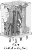
R10-T2W3-J30.0K
POWER RELAY, 3PDT, 65VDC, 7.5A, PLUG IN
⚠️ Reference pricing provided. In case of supply shortages, we will connect you with our trusted procurement partners to ensure your project's continuity.
- Manufacturer: Potter&Brumfield
- Product type: Power Relays
- Coil Voltage: 8.3VDC
| Delivery and price | |
|---|---|
| Units per pack | 250 |
| Price | 103.85 € |
| Current stock | 10+ |
| Lead time | 30 days |
Datasheet

General Purpose Relays Industrial Relays

**Potter & Brumfield**

## **R10 Series Panel Plug-in Relay**

- n **1 through 8 form C (CO) contact arrangement**

- n **Broad range of coil options provides sensitivity ranging from 25 to 750mW**

- n **Various contacts switch from dry circuit to 7.5 amps**

- n **Many mounting and termination options**

## Typical applications

Coin changers, audio equipment, elevators, traffic controls, ultrasonic test equipment, parking toll readers

**==> picture [208 x 7] intentionally omitted <==**

**----- Start of picture text -----**<br>
R10  R10-R  R10S   R10-T<br>**----- End of picture text -----**<br>


|~~**Approvals**~~||||**Contact ratings**(continued)|**Contact ratings**(continued)||||
|---|---|---|---|---|---|---|---|---|
|UL E29244; CSA LR15734||||Type|Load|||Cycles|
|Technical data of approved types on request||||**UL 508**|||||
|||||P type, Au overlay Ag, bifurcated crossbar contact|||||
|~~**Contact Data**~~|||||2A, 120VAC, resistive|||100x103|
|Contact arrangement|1, 2, 3, 4, 6 and 8 Form C (CO)|1, 2, 3, 4, 6 and 8 Form C (CO)|||3 A, 120 VAC, resistive|||6x10³|
|Rated voltage||120VAC|||3 A, 30 VDC, resistive|||100x103|
|Rated current||7.5A||L type, AuPtAg, bifurcated crossbar contact|||||
|Contact material<br>Ag, AgCdO, Au overlay Ag, AuPtAg|||||500mA, 28VDC, resistive|||6x10³|
|Contact style<br>Single or bifurcated crossbar|Single or bifurcated crossbar|||Mechanical endurance               10x10||Mechanical endurance               10x106ops., except W type is 1x10||ops., except W type is 1x10⁶ops.|
|Min. recommended contact load|||||||||
|W type, AgCdO, single contact|300mA, 12VDC||||||||
|X type, AgCdO, single contact|300mA, 12VDC|||~~**Coil Data**~~|||||
|M type, AgCdO, bifurcated contact|M type, AgCdO, bifurcated contact<br>300mA, 12VDC|||Coil voltage range|||3 to 115VDC||
|Y type, Ag, single contact|100mA, 12VDC||||||4.5mA to 20mA|4.5mA to 20mA|
|Z type, Ag, bifurcated crossbar|1mA, 12VDC||||||6 to 115VAC||
|P type, Au overlay Ag, bifurcated crossbar||dry circuit||**Coil versions, DC coil**|||||
|L type, AuPtAg, bifurcated crossbar|L type, AuPtAg, bifurcated crossbar|dry circuit||Coil|Rated|Operate|Coil|Rated coil|
|Initial contact resistance||||code|voltage|voltage|resistance|power|
|All AgCdO contact types||100mΩ|||VDC|VDC|Ω±10%|mW|
|All other contact materials and types|All other contact materials and types|50mΩ||V - standard DC voltage adjustment|||||
|Frequency of operation||360 ops./hr||1, 2 and 4 pole|1, 2 and 4 pole||||
|||||V10|3|2.25|10|900|
|**Contact ratings**||||V28|5|3.75|28|900|
|Type<br>Load||Cycles||V52|6|4.5|52|900|
|**UL 508**||||V185|12|9|185|900|
|W type, AgCdO, single contact||||V700|24|18|700|900|
|7.5A, 120VAC, resistive|7.5A, 120VAC, resistive|||V2.5K|48|36|2500|900|
|7.5A, 28VDC, resistive||||V5.8K|72|54|5800|900|
|1/8HP, 120VAC, same polarity||||V15.0K|115|86|15000|900|
|1/6HP, 240VAC, same polarity||||6 pole|||||
|X type, AgCdO, single contact||||V6|3|2.25|6|1,500|
|2A, 30VDC, resistive||100x103||V16|5|3.75|16|1,600|
|5A, 120VAC, resistive||6x10³||V25|6|4.5|25|1,500|
|5A, 30VDC, resistive||100x103||V90|12|9|90|1,600|
|1/20HP, 120VAC, same polarity||1/20HP, 120VAC, same polarity||V430|24|18|430|1,400|
|1/10HP, 240VAC, same polarity||1/10HP, 240VAC, same polarity||V1.5K|48|36|1500|1,600|
|M type, AgCdO, bifurcated contact||||V3.5K|72|54|3500|1,500|
|5A, 120VAC, resistive||6x10³||V9.0K|115|86|9000|1,500|
|5A, 28VDC, resistive||6x10³||8 pole|||||
|Y type, Ag, single contact||||V5|3|2.25|5|1,800|
|2A, 120VAC||6x10³||V14|5|3.75|14|1,800|
|2A, 28VDC||6x10³||V20|6|4.5|20|1,800|
|250VA, 250VAC||30x103||V72|12|9|72|2,000|
|125VA, 125VAC||100x103||V350|24|18|350|1,700|
|Z type, Ag, bifurcated crossbar contact||||V1.25K|48|36|1250|1,900|
|3A, 120VAC||6x10³||V2.8K|72|54|2800|1,900|
|3A, 28VDC||6x10³||V8.0K|115|86|8000|1,700|
|2A, 30VDC||100x103||All figures aregiven for coil withoutpreenergization,at ambient temperature +23°C.||||erature +23°C.|


1

Datasheets and product specification according to IEC 61810-1 and to be used only together with the ‘Definitions’ section.

Datasheets, product data, ‘Definitions’ section, application notes and all specifications are subject to change.

09-2010, Rev. 0910

Datasheets and product data is subject to the terms of the disclaimer and all chapters of the ‘Definitions’ section, available at http://relays.te.com/definitions

www.te.com © 2010 Tyco Electronics Ltd.

General Purpose Relays Industrial Relays

**Potter & Brumfield**

## **R10 Series Panel Plug-in Relay** (Continued)

|**Coil versions, DC coil**(continued)<br>Coil<br>Rated<br>Operate<br>Coil<br>Rated coil<br>code<br>voltage<br>voltage<br>resistance<br>power<br>VDC<br>VDC<br>Ω±10%<br>mW<br>Q - special DC voltage adjustment<br>1 and 2 pole<br>Q52<br>5<br>3.1<br>52<br>500<br>Q110<br>6<br>4.5<br>110<br>350<br>Q450<br>12<br>9.2<br>450<br>350<br>Q1.8K<br>24<br>17.4<br>1,800<br>350<br>Q7.5K<br>48<br>36.2<br>7500<br>310<br>Q15.0K<br>72<br>49.5<br>15000<br>350<br>Q30.0K<br>115<br>67.5<br>30000<br>450<br>3 and 4 pole<br>Q32<br>5<br>3.8<br>32<br>800<br>Q52<br>6<br>4.2<br>52<br>700<br>Q185<br>12<br>8.4<br>185<br>800<br>Q1.0K<br>24<br>17.2<br>1000<br>600<br>Q3.2K<br>48<br>31.1<br>3200<br>750<br>Q7.5K<br>72<br>49.3<br>7500<br>700<br>Q15.0K<br>115<br>67.5<br>15000<br>900<br>S - sensitive DC voltage adjustment<br>1 and 2 pole<br>S50<br>3<br>2.25<br>50<br>180<br>S140<br>5<br>3.75<br>140<br>180<br>S200<br>6<br>4.5<br>200<br>180<br>S800<br>12<br>9<br>800<br>180<br>S3.2K<br>24<br>18<br>3200<br>180<br>S13.0K<br>48<br>36<br>13000<br>180<br>S28.0K<br>72<br>54<br>28000<br>190<br>S50.0K<br>115<br>86<br>50000<br>270<br>3 and 4 pole<br>S30<br>3<br>2.25<br>30<br>300<br>S80<br>5<br>3.75<br>80<br>350<br>S110<br>6<br>4.5<br>110<br>350<br>S450<br>12<br>9<br>450<br>350<br>S1.8K<br>24<br>18<br>1800<br>350<br>S7.5K<br>48<br>36<br>7500<br>300<br>S16.0K<br>72<br>54<br>16000<br>350<br>S40.0K<br>115<br>86<br>40000<br>350<br>6 pole<br>S20<br>3<br>2.25<br>20<br>500<br>S56<br>5<br>3.75<br>56<br>500<br>S80<br>6<br>4.5<br>80<br>500<br>S320<br>12<br>9<br>320<br>500<br>S1.2K<br>24<br>18<br>1200<br>500<br>S5.2K<br>48<br>36<br>5200<br>500<br>S13.0K<br>72<br>54<br>13000<br>400<br>S30.0K<br>115<br>86<br>30000<br>500<br>8 pole<br>S12<br>3<br>2.25<br>12<br>750<br>S35<br>5<br>3.75<br>35<br>750<br>S52<br>6<br>4.5<br>52<br>700<br>S200<br>12<br>9<br>200<br>750<br>S800<br>24<br>18<br>800<br>750<br>S3.2K<br>48<br>36<br>3200<br>750<br>S7.5K<br>72<br>54<br>7500<br>700<br>S16.0K<br>115<br>86<br>16000<br>850<br>SS - ultra sensitive DC voltage adjustment<br>1 pole<br>SS220<br>3<br>2.25<br>220<br>45<br>SS700<br>5<br>3.75<br>700<br>40<br>SS1.0K<br>6<br>4.5<br>1000<br>40<br>SS4.0K<br>12<br>9<br>4000<br>40<br>SS9.0K<br>18<br>13.5<br>9000<br>40<br>SS15.0K<br>24<br>18<br>15000<br>40<br>SS30.0K<br>36<br>27<br>30000<br>45|**Coil versions, DC coil**(continued)|
|---|---|
||Coil<br>Rated<br>Operate<br>Coil<br>Rated coil<br>code<br>voltage<br>voltage<br>resistance<br>power<br>VDC<br>VDC<br>Ω±10%<br>mW|
||S - sensitive DC voltage adjustment (continued)<br>2 pole<br>SS110<br>3<br>2.25<br>110<br>85<br>SS350<br>5<br>3.75<br>350<br>75<br>SS500<br>6<br>4.5<br>500<br>75<br>SS2.0K<br>12<br>9<br>2000<br>75<br>SS4.5K<br>18<br>13.5<br>4500<br>75<br>SS7.5K<br>24<br>18<br>7500<br>80<br>SS15.0K<br>36<br>27<br>15000<br>85<br>SS30.0K<br>48<br>36<br>30000<br>80|
||3 and 4 pole<br>SS52<br>3<br>2.25<br>52<br>175<br>SS175<br>5<br>3.75<br>175<br>150<br>SS250<br>6<br>4.5<br>250<br>150<br>SS1.0K<br>12<br>9<br>1000<br>150<br>SS2.2K<br>18<br>13.5<br>2200<br>150<br>SS3.7K<br>24<br>18<br>3700<br>150<br>SS7.5K<br>36<br>27<br>7500<br>175<br>SS15.0K<br>48<br>36<br>15000<br>150|
|||
||Coil<br>Maximum<br>Operate<br>Coil<br>Pick-up<br>code<br>coil current<br>current<br>resistance<br>coil power<br>mADC<br>mADC<br>Ω±10%<br>mW|
||J - sensitive DC current adjustment<br>2 pole<br>J1.0K<br>45<br>8.5<br>1000<br>75<br>J2.5K<br>28<br>5.8<br>2500<br>85<br>J5.0K<br>20<br>4.1<br>5000<br>85<br>J10.0K<br>14<br>3.1<br>10000<br>100<br>J15.0K<br>11.5<br>2.6<br>15000<br>100<br>J30.0K<br>8.3<br>1.7<br>30000<br>85|
||4 pole<br>J1.0K<br>45<br>13<br>1000<br>175<br>J2.5K<br>28<br>8.4<br>2500<br>175<br>J5.0K<br>20<br>6.2<br>5000<br>200<br>J10.0K<br>14<br>4.5<br>10000<br>200<br>J15.0K<br>11.5<br>3.5<br>15000<br>200<br>J30.0K<br>8.3<br>2.5<br>30000<br>200|
||6 pole<br>J1.0K<br>45<br>16<br>1000<br>250<br>J2.5K<br>28<br>10<br>2500<br>250<br>J5.0K<br>20<br>7.2<br>5000<br>250<br>J10.0K<br>14<br>5<br>10000<br>250<br>J15.0K<br>11.5<br>4.2<br>15000<br>270<br>J30.0K<br>8.3<br>2.9<br>30000<br>250|
||8 pole<br>J1.0K<br>45<br>20<br>1000<br>250<br>J2.5K<br>28<br>13<br>2500<br>250<br>J5.0K<br>20<br>9<br>5000<br>250<br>J10.0K<br>14<br>6.4<br>10000<br>250<br>J15.0K<br>11.5<br>5.3<br>15000<br>270<br>J30.0K<br>8.3<br>3.7<br>30000<br>250|
||J - sensitive DC current adjustment - R10S types only<br>1 pole<br>J5001)<br>–<br>4.5<br>500<br>10<br>J1.0K1)<br>–<br>3.2<br>1000<br>10<br>J2.5K<br>–<br>2<br>2500<br>10<br>J5.0K2)<br>–<br>1.4<br>5000<br>10<br>J10.0K<br>–<br>1<br>10000<br>10<br>J16.0K<br>–<br>0.8<br>16000<br>10<br>J30.0K3)<br>–<br>0.6<br>30000<br>11|
|||


2

Datasheets and product specification according to IEC 61810-1 and to be used only together with the ‘Definitions’ section.

Datasheets and product data is subject to the Datasheets, product data, ‘Definitions’ secterms of the disclaimer and all chapters of tion, application notes and all specifications the ‘Definitions’ section, available at are subject to change. http://relays.te.com/definitions

09-2010, Rev. 0910

www.te.com © 2010 Tyco Electronics Ltd.

General Purpose Relays Industrial Relays

**Potter & Brumfield**

## **R10 Series Panel Plug-in Relay** (Continued)

|**Coil versions, DC coil**(continued)<br>Coil<br>Maximum<br>Operate<br>Coil<br>Pick-up<br>code<br>coil current<br>current<br>resistance<br>coil power<br>mADC<br>mADC<br>Ω±10%<br>mW<br>J - sensitive DC current adjustment – R10S types only<br>2 pole<br>J5001)<br>–<br>6.3<br>500<br>20<br>J1.0K<br>–<br>4.5<br>1000<br>20<br>J2.5K2)<br>–<br>2.9<br>2500<br>25<br>J5.0K<br>–<br>2<br>5000<br>20<br>J10.0K3)<br>–<br>1.4<br>10000<br>20<br>J16.0K<br>–<br>1.2<br>16000<br>25<br>J30.0K<br>–<br>0.8<br>30000<br>20<br>4 pole<br>J500<br>–<br>9<br>500<br>45<br>J1.0K<br>–<br>6.5<br>1000<br>45<br>J2.5K2)<br>–<br>4.1<br>2500<br>45<br>J5.0K3)<br>–<br>2.9<br>5000<br>45<br>J10.0K<br>–<br>2<br>10000<br>40<br>J16.0K<br>–<br>1.4<br>16000<br>35<br>J30.0K<br>–<br>1.2<br>30000<br>45<br>1) Suggested for 5VDC operation<br>2) Suggested for 12VDC operation<br>3) Suggested for 24VDC operation<br>JJ - ultrasensitive DC current adjustment<br>1 pole<br>JJ1.0K<br>45<br>4.5<br>1000<br>20<br>JJ2.5K<br>28<br>2.9<br>2500<br>25<br>JJ5.0K<br>20<br>2.1<br>5000<br>25<br>JJ10.0K<br>14<br>1.5<br>10000<br>25<br>JJ15.0K<br>11.5<br>1.2<br>15000<br>25<br>JJ30.0K<br>8.3<br>0.85<br>30000<br>25<br>2 pole<br>JJ1.0K<br>45<br>6.5<br>1000<br>45<br>JJ2.5K<br>28<br>4.1<br>2500<br>45<br>JJ5.0K<br>20<br>2.9<br>5000<br>45<br>JJ10.0K<br>14<br>2<br>10000<br>40<br>JJ15.0K<br>11.5<br>1.7<br>15000<br>45<br>JJ30.0K<br>8.3<br>1.2<br>30000<br>45<br>4 pole<br>JJ1.0K<br>45<br>9<br>1000<br>85<br>JJ2.5K<br>28<br>5.8<br>2500<br>85<br>JJ5.0K<br>20<br>4.1<br>5000<br>85<br>JJ10.0K<br>14<br>3<br>10000<br>90<br>JJ15.0K<br>11.5<br>2.4<br>15000<br>85<br>JJ30.0K<br>8.3<br>1.7<br>30000<br>90<br>All fgures aregiven for coil withoutpreenergization,at ambient temperature +23°C.<br>**Coil versions, AC coil (dual coil diode rectifed construction)**<br>Coil<br>Rated<br>Operate<br>Coil<br>code<br>voltage<br>voltage<br>resistance<br>VAC<br>VAC<br>Ω±20%<br>Standard AC<br>2 and 4 pole<br>6V<br>6<br>5<br>25<br>12V<br>12<br>9<br>120<br>24V<br>24<br>18<br>500<br>48V<br>48<br>36<br>2000<br>115V<br>115<br>86<br>9000<br>6 and 8 pole<br>6V<br>6<br>5<br>15<br>12V<br>12<br>9<br>90<br>24V<br>24<br>18<br>350<br>48V<br>48<br>36<br>1400<br>115V<br>115<br>86<br>7500|Operative Range<br>R10 Relays (DC Only) Typical Ranges of Operations @ 25°C<br>R10 Ultra-Sensitive “SS” and “JJ” Typical Ranges of Operation @ 25°C<br>Typical Coil Inductance<br>Operate Time<br>Multiple of Max. Pull-in Voltage or Current<br>Operate Time (Milliseconds)<br>Release Time (Milliseconds)<br>30<br>25<br>20<br>15<br>10<br>Release Time<br>(no suppression)<br>5<br>12<br>10<br>8<br>6<br>4<br>2<br>1.0<br>1.33 1.5<br>2.0<br>2.5<br>3.0<br>(Curves for reference only. If specifc<br>values are required, testing is required.)<br>Typical Operate<br>and Release Time<br>(all contact confgurations)<br>50<br>40<br>30<br>20<br>10<br>1.0<br>1.5<br>2.0<br>3.0<br>4.0<br>10<br>8<br>6<br>4<br>2<br>Operate Time<br>(Curves for reference only. If specifc<br>values are required, testing is required.)<br>Release Time<br>(no suppression)<br>Typical Operate<br>and Release Time<br>(all contact confgurations)<br>Multiple of Max. Pull-in Voltage or Current<br>Operate Time (Milliseconds)<br>Release Time (Milliseconds)<br>Coil Inductance (Henrys)<br> <br>500<br>100<br>50<br>10<br>1.0<br>0.5<br>0.110<br>50 100<br>500<br>1K<br>5K 10K<br>100K<br>Armature (open)<br>Armature (closed)|
|---|---|
||~~Coil Resistance (Ohms)~~|


All figures are given for coil without preenergization, at ambient temperature +23°C.

3

Datasheets and product specification according to IEC 61810-1 and to be used only together with the ‘Definitions’ section.

Datasheets, product data, ‘Definitions’ section, application notes and all specifications are subject to change.

09-2010, Rev. 0910

Datasheets and product data is subject to the terms of the disclaimer and all chapters of the ‘Definitions’ section, available at http://relays.te.com/definitions

www.te.com © 2010 Tyco Electronics Ltd.

**General Purpose Relays Industrial Relays**

**Potter & Brumfield**

## **R10 Series Panel Plug-in Relay** (Continued)

|~~**I**~~<br>In<br>I<br>~~**O**~~<br>M<br>A<br>C|~~**nsulation Data**~~<br>itial dielectric strength<br>between open contacts<br>500Vrms<br>between contact and coil<br>1000Vrms<br>between adjacent contacts<br>1000Vrms<br>nitial insulation resistance<br>between insulated elements<br>10GΩ, 500VDC<br>~~**ther Data**~~<br>aterial compliance: EU RoHS/ELV, China RoHS, REACH, Halogen content<br>refer to the Product Compliance Support Center at<br>www.te.com/customersupport/rohssupportcenter<br>mbient temperature<br>-55ºC to 75ºC<br>ategory of environmental protection<br>IEC 61810<br>RTI-dust protected and RTIII-wash tight|
|---|---|


||~~**Other Data**(continued)~~||
|---|---|---|
||Terminal type|Solder/plug-in terminals, PCB-THT,|
|||8-or 11-PIN octal type plug|
||Weight|23 to 40g|
||Packaging/unit|tray/50 pcs., box/350pcs.|
||||
||~~**Accessories**~~||
||For details see datasheet|Sockets and Accessories, R10 Relays|
||Product Code Description||
||Many versions of sockets and|clips available.|


## **Dimensions**

**==> picture [533 x 499] intentionally omitted <==**

**----- Start of picture text -----**<br>
1.187 MAX .<br>(30.15)<br>.735 MAX. R10S: 1.50 MAX. CASE R ONLY<br>(18.67) CASE E (38.1) Recommend tape tab<br>ONLY be removed after<br>2 POLE .950 MAX. immersion cleaning<br>(24.13, 2 POLE 1R10) and before relay is put<br>.406 4 POLE 1.165 MAX. in service. Peel off to<br>(10.31) .085 MAX. (29.59, 4 POLE 1R10)6 POLE 1.375 MAX. permit proper relay<br>(2.16) (34.93) ventilation.<br>.135 8 POLE 1.580 MAX.(40.13)<br>(3.43)<br>.171<br>.354<br>(4.43) TYPE E6 ONLY<br>(8.99)<br>.210<br>(5.33) .375 .156<br>NIB .091 DIA. x .020 HIGH3-48 THREAD } [TYPE E1 ONLY] THREAD#6-32 (9.53) (3.96)<br>(2.31)    (.51)<br>TYPE E6 ONLY<br>.59 REF.<br>(15.0) .437<br>(11.10)<br>STUD ON NARR OW<br>SIDE ONLY<br>Terminal dimensions<br>Solder terminal dimensions  Printed circuit terminal dimensions<br>.090 A B C D Arrang.<br>(2.29) .040 B Type 2 .131 .050 .064 1.251 Inline<br>(1.02) Type 7 .131 .040 .013 1.20 Inline<br>C A Type 9 .170 .040 .000 1.187 Staggered<br>D Thickness .012 .012 .012 .013 –––<br>.080 .012 (TO TOP OF CASE)<br>(2.03) (.30)<br>Terminal assignment<br>R10 - AC Coil Diagram<br>28     15       16<br>26      27       14<br>22     12       13 25     12       13<br>20      21      11 23      24      11<br>16       9       10 16       9       10 19       9       10 22       9       10<br>DUAL<br>14     15        8 14     15        8 17      18       8 20      21       8 COIL<br>10       6        7 10       6        7 13       6        7 13       6        7 16       6        7 19       6        7<br> 8        9        5  8        9        5 11     12        5 11     12        5 14      15       5 17      18       5<br>4    3    2     1 4    3    2     1 4    3    2     1 4    3    2     1 4    3    2     1 4    3    2     1<br>1 POLE 2 POLE 3 POLE 4 POLE 6 POLE 8 POLE<br>4<br>09-2010, Rev. 0910 Datasheets and product specifcation ac- Datasheets and product data is subject to the  Datasheets, product data, ‘Defnitions’ sec-nitions’ sec-<br>cording to IEC 61810-1 and to be used only  terms of the disclaimer and all chapters of  tion, application notes and all specifcations cations<br>www.te.com together with the ‘Defnitions’ section. the ‘Defnitions’ section, available at nitions’ section, available at  are subject to change.<br>**----- End of picture text -----**<br>


**Datasheets and product data is subject to the Datasheets, product data, ‘Defnitions’ sec-nitions’ secterms of the disclaimer and all chapters of tion, application notes and all specifcations cations the ‘Defnitions’ section, available at nitions’ section, available at are subject to change. http://relays.te.com/definitions**

**www.te.com © 2010 Tyco Electronics Ltd.**

**General Purpose Relays Industrial Relays**

**Potter & Brumfield**

## **R10 Series Panel Plug-in Relay** (Continued)

**==> picture [519 x 581] intentionally omitted <==**

**----- Start of picture text -----**<br>
PCB layout  Suggested panel cutout for relay  Mounting hole layout for<br>Bottom view on solder pins terminal & mounting style 6<br>Terminal Types E2 & R2  Terminal Types E9 & R9<br>(Omit unnecessary holes)  (Omit unnecessary holes)<br>2 HOLES .187 ± .002 DIA.<br>.210 (12.70).500 .109 + .005– .000 DIA. TOLERANCE: (± .25) [± .010] (4.75 ± .05)<br>.320(5.33) .420 (13.46).530 (18.80).740 (2.54)GRID.100 6 (           )2.77+ .13– .00 X (11.10).437<br>(8.13) (10.67) POLE<br>(2.79).110 (10.16)(11.43).400.450 (13.97).550(        .0561.42HOLES+ .004+ .10- .000- .00(16.00).630)DIA. .056(        )1.42HOLES+ .004- .000+ .10- .00 DIA.(12.70).500 (11.43).450 (3.81)POLE.1502 POLE(2.54)4.100 (16.66 ± .38).656 ± .015(7.14).281X = 2 POLE – .343 ± .020                 (8.71 ± .51)(8.99).354 (3.56).140 .281 ± .015(7.14 ± .38) .147 ± .002 DIA.(3.73 ± .05)<br>4 POLE – .562 ± .020<br>                 (14.27 ± .51)<br>6 POLE – .781 ± .020<br>                 (19.84 ± .51)<br>8 POLE – 1.000 ± .020<br>                 (25.40 ± .51)<br>Product code structure  Typical product code  R10  -E  1  Y  4  -V700<br>Type<br>R10  Cradle-style relay with form C contacts<br>R10S  Super sensitive cradle-style relay with form C contacts<br>Case style<br>E  Non-sealed polycarbonate dust cover (RTI)<br>R  Wash-tight (RTIII), tape sealed plastic case   [1)]<br>T  Octal style base on non-sealed polycarbonate dust cover (terminal types 1 & 2 only; 1, 2 & 3 poles only)<br>  1) R10 type only, terminal code 2 or 9 only, no ground or stud<br>Terminal and mounting<br>1  Solder/Plug-in terminals with #3-48 mounting stud on R10-E; 8-pin octal type on R10-T<br>2 PCB terminals (std.) 1.62mm (.064in) clearance, 31.75mm (1.25in) seated ht.; 11-pin octal type on R10-T<br>6 Side mounting plate with #6-32 stud, solder/plug-in terminals (#3-48 stud not included)<br>7 Narrow 1.02mm (.04in) PCB terminals, .33mm (.013in) clearance, 30.48mm (1.2in) seated ht.<br>9 Non-shouldered, narrow 1.02mm (.04in) PCB terminals in staggered arrangement  [ 2)]<br>2) Available only on 1 through 6 pole models<br>Contact style and rating    [3)]<br>W  Single contact rated 7.5A max, 300mA min.  [4)  5)]<br>X  Single contact rated 5A max, 300mA min.   [5)  6)]<br>M  Bifurcated contact rated 5A max, 300 mA min.  [5) 6)]<br>Y  Single contact rated 2A typ, 3A max, 100mA min.<br>Z  Bifurcated low level contacts rated 100mA typ, 2A max, 1mA min.<br>P  Bifurcated crossbar dry circuit contacts rated 1mA typ, 3A max, dry circuit min.<br>L  Bifurcated crossbar dry circuit contacts rated 500 microA typ, 250 mA max, dry circuit min.<br>  3) Ratings are at 28VDCV or 115VAC. Total load must not exceed 30A per relay.<br>  4) Use ungrounded frame for AC load of ≥5A. Max ratings are 7.5A at 115VAC and 4A at 28VDC for coil codes S & J<br>  5) Only available on R10 type, only available with coil adjustment code V, Q, S and J.<br>—   6) Use ungrounded frame for AC load of ≥5A. Max ratings are 5A at 115VAC and 3A at 28VDC for coil codes S & J<br>Number of poles<br>1  1 pole  4  4 pole (not available on R10-T)<br>2  2 pole  6  6 pole (not available on R10-T)  [7)]<br>3  3 pole  8  8 pole (not available on R10-T)   [8)]<br>  7) Not available with contact code W<br>  8) Only available with case style E, not available with contact code W<br>**----- End of picture text -----**<br>


- **Coil voltage**

   - Coil code: please refer to coil versions table

**AC voltage** Specify coil code consisting of nominal coil voltage followed by W (example: 24V)

- **DC voltage** Specify coil code consisting of coil adjustment code letter followed by coil resistance (example: V700)

5

Datasheets and product specification according to IEC 61810-1 and to be used only together with the ‘Definitions’ section.

Datasheets, product data, ‘Definitions’ section, application notes and all specifications are subject to change.

09-2010, Rev. 0910

Datasheets and product data is subject to the terms of the disclaimer and all chapters of the ‘Definitions’ section, available at http://relays.te.com/definitions

www.te.com © 2010 Tyco Electronics Ltd.

**General Purpose Relays Industrial Relays**

**Potter & Brumfield**

## **R10 Series Panel Plug-in Relay** (Continued)

**==> picture [520 x 516] intentionally omitted <==**

**----- Start of picture text -----**<br>
Product Code Arrangement Material Contact Style/Rating Nom. Coil V Terminals & Mounting Part Number<br>R10-E1P2-115V 2 Form C, 2 CO Au overlay Ag Bif crossbar / dry circuit 115 VAC Solder/plug-in w/ #3-48 mounting stud 7-1393765-0<br>R10-E1P2-V700 24 VDC 6-1393765-9<br>R10-E1P4-115V 4 Form C, 4 CO 115 VAC 7-1393765-6<br>R10-E1P4-V700 24 VDC 7-1393765-5<br>R10-E1W2-V185 2 Form C, 2 CO  AgCdO Single contact / 7.5A 12 VDC 8-1393765-9<br>R10-E1W2-V700 24 VDC 9-1393765-1<br>R10-E1W4-V185 4 Form C, 4 CO 12 VDC 9-1393765-3<br>R10-E1W4-V700 24 VDC 9-1393765-5<br>R10-E1X2-24V 2 Form C, 2 CO  Single contact / 5A 24 VAC 1-1393766-1<br>R10-E1X2-115V 115 VAC 1-1393766-0<br>R10-E1X2-S800 12 VDC 1393766-3<br>R10-E1X2-V185 1393766-5<br>R10-E1X2-V700 24 VDC 1393766-9<br>R10-E1X4-115V 4 Form C, 4 CO 115 VAC 1-1393766-8<br>R10-E1X4-V185 12 VDC 1-1393766-4<br>R10-E1X4-V700 24 VDC 1-1393766-7<br>R10-E1X4-V2.5K 48 VDC 1-1393766-5<br>R10-E1X6-115V 6 Form C, 6 CO 115 VAC 2-1393766-5<br>R10-E1X6-V90 12 VDC 2-1393766-4<br>R10-E1X6-V430 24 VAC 2-1393766-2<br>R10-E1Y2-J1.0K 2 Form C, 2 CO  Ag Single contact / 2A typical Not applicable 3-1393766-3<br>R10-E1Y2-J2.5K 3-1393766-4<br>R10-E1Y2-V185 12 VDC 4-1393766-0<br>R10-E1Y2-V700 24 VDC 4-1393766-4<br>R10-E1Y2-V2.5K 48 VDC 4-1393766-1<br>R10-E1Y2-V15.0K 115 VDC 3-1393766-9<br>R10-E1Y4-J10.0K 4 Form C, 4 CO Not applicable 4-1393766-9<br>R10-E1Y4-V52 5-1393766-6<br>R10-E1Y4-V2.5K 48 VDC 5-1393766-5<br>R10-E1Y4-V700 24 VDC 5-1393766-7<br>R10-E1Y6-V430 6 Form C, 6 CO 6-1393766-1<br>R10-E1Y6-V1.5K 48 VDC 6-1393766-0<br>R10-E1Z2-V185 2 Form C, 2 CO  Bifurcated / 100mA typical 12 VDC 7-1393766-2<br>R10-E1Z2-V700 24 VDC 7-1393766-4<br>R10-E1Z4-V185 4 Form C, 4 CO 12 VDC 7-1393766-9<br>R10-E1Z4-V700 24 VDC 8-1393766-1<br>R10-E1Z4-V2.5K 48 VDC 8-1393766-0<br>R10-E1Z6-V430 6 Form C, 6 CO 24 VDC 8-1393766-6<br>R10-E1Z6-V1.5K 48 VDC 8-1393766-5<br>R10-T1P2-115V 2 Form C, 2 CO Au overlay Ag Bif crossbar / dry circuit 115 VAC 2-1393769-8<br>R10S-E1Y1-J1.0K 1 Form C, 1 CO Ag Single contact / 2A typical Not applicable 7-1393769-0<br>R10S-E1Y2-J5.0K 2 Form C, 2 CO  7-1393769-5<br>R10-E2P4-V185 4 Form C, 4 CO Au overlay Ag Bif crossbar / dry circuit 12 VDC PCB, .064" clearance, 1.25" seated ht. 1393767-3<br>R10-E2P4-V700 24 VDC 1393767-4<br>R10-E2W2-V185 2 Form C, 2 CO  AgCdO Single contact / 5A 12 VDC 1393767-7<br>R10-E2X2-V185 1-1393767-1<br>R10-E2X2-V700 24 VDC 1-1393767-5<br>R10-E2X4-V185 4 Form C, 4 CO 12 VDC 1-1393767-7<br>R10-E2X4-V700 24 VDC 1-1393767-8<br>R10-E2Y2-V185 2 Form C, 2 CO  Ag Single contact / 2A typical 12 VDC 2-1393767-6<br>R10-E2Y2-V700 24 VDC 2-1393767-9<br>R10-E2Y4-V185 4 Form C, 4 CO 12 VDC 3-1393767-5<br>R10-E2Y4-V700 24 VDC 3-1393767-6<br>R10S-E2Y1-J1.0K 1 Form C, 1 CO Not applicable 8-1393769-1<br>**----- End of picture text -----**<br>


6

Datasheets and product specification according to IEC 61810-1 and to be used only together with the ‘Definitions’ section.

Datasheets, product data, ‘Definitions’ section, application notes and all specifications are subject to change.

09-2010, Rev. 0910

Datasheets and product data is subject to the terms of the disclaimer and all chapters of the ‘Definitions’ section, available at http://relays.te.com/definitions

www.te.com © 2010 Tyco Electronics Ltd.
Updated at February 9, 2023
About Novapart
Novapart is a B2B electronic component broker specialising in stock shortages and cost reduction. We source hard-to-find parts and identify compliant alternatives across a catalogue of 410,000+ components from 500+ manufacturers.
Learn more →Stock Shortage Specialist
When a component is unavailable, discontinued or has an unacceptable lead time, we tap into our network of vetted European and Asian distributors to source what you need — without compromising on quality or traceability.
Request a quote →Compliant Alternatives
We identify pin-to-pin, electrically equivalent substitutes that meet the same certifications (RoHS, AEC-Q100, REACH) as your original specification — validated against datasheets, not just part numbers. Often at a lower cost.
BOM Analysis service →