
Image not available
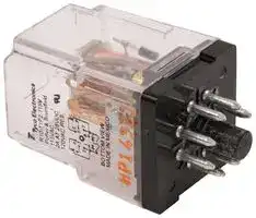
Illustrative purposes only

R10-T1P2-115V
POWER RELAY, DPDT, 3A, 120VAC, SOCKET
⚠️ Reference pricing provided. In case of supply shortages, we will connect you with our trusted procurement partners to ensure your project's continuity.
- Manufacturer: TE CONNECTIVITY - POTTER&BRUMFIELD
- Product type: Power Relays
- C; POWER RELAY, DPDT, 3A, 120VAC, SOCKET; Contact Configuration:DPDT; Coil Voltage:115VAC; Contact Current:3A; Product Range:R10 Series; Relay Mounting:Socket; Coil Type:Non Latchin
- Coil Type: Non Latching
- Coil Voltage: 115VAC
- Product Range: R10 Series
- Relay Mounting: Socket
- Coil Resistance: 9kohm
- Contact Current: 3A
- Relay Terminals: Plug In
- Contact Material: Silver
- Contact Voltage VAC: 120V
- Contact Voltage VDC: 30V
- Contact Configuration: DPDT
| Delivery and price | |
|---|---|
| Units per pack | 1 |
| Price | 76.73 € |
| Current stock | 100+ |
| Lead time | 30 days |
Datasheet

Catalog 1308242 Issued 3-03

_P&B_

## R10 series

## **General Purpose Dry Circuit to 7.5 Amp Multicontact AC or DC Relay**

- R10-E – Clear Dust Cover Version

- R10-R – Sealed, Immersion Cleanable Type

- R10S – Super Sensitive, Logic Compatible

## File E29244

## File LR15734

**==> picture [160 x 7] intentionally omitted <==**

**----- Start of picture text -----**<br>
R10 R10-R R10S<br>**----- End of picture text -----**<br>


Users should thoroughly review the technical data before selecting a product part number. It is recommended that user also seek out the pertinent approvals files of the agencies/laboratories and review them to ensure the product meets the requirements for a given application.

## **Features**

- Broad range of coil options provide sensitivity ranging from 25 to 750mW.

- Various contacts switch from dry circuit to 7.5 amps.

- Many mounting and termination options.

## **Capacitance**

**Between Contacts:** 2 pf, typ. **Between Contacts and Coil:** 2 pf, typ. **Between Coil and Frame:** 30 pf, typ.

## **Initial Insulation Resistance**

## **Contact Data @ 25** ° **C**

**Between Mutually Insulated Elements:** 10[10] ohms @ 25°C, 50% RH. Consult factory for optional acetal resin material rated 10[12] ohms.

**Arrangements:** 1 Form C (SPDT) through 8 Form C (8PDT)  See Ordering Information tables for more details regarding availability.

## **Coil Data @ 25** ° **C (also see Coil Data tables)**

## **Contact Materials, Styles & Ratings @ +25** ° **C**

**Voltage:** 3 to 115VDC and 6 to 115VAC. **Maximum Coil Power:** 2.2 Watts.

|**Contact**<br>**Code**|**Contact**<br>**Contact**<br>**Material**|**Contact**<br>**Style**|**Coil Codes**<br>**Available**|**Coil Codes**<br>**Contact Ratings**|**Coil Codes**<br>**Contact Ratings**|**Coil Codes**<br>**Contact Ratings**|
|---|---|---|---|---|---|---|
|||||**Min.**|**Typ.**|**Max.**|
|W<br>X<br>Y<br>Z<br>P|Silver-Cadmium Oxide<br>Silver-Cadmium Oxide<br>Fine Silver<br>Fine Silver<br>Gold overlay on Silver|Single Button<br>Single Button<br>Single Button<br>Bifurcated<br> Bifurcated Crossbar|V, Q, S, J<br>V, Q, S, J<br>All<br>All<br>All|500mA<br>500mA<br>100mA<br>1mA<br>Dry Circuit|-<br>-<br>2A<br>100mA<br>1mA|7.5A‡<br>5A§<br>3A<br>2A<br>3A|


**Coil Temperature Rise:** 30°C per Watt.

**Maximum Coil Temperature:** 105°C.

## **Operate Data @ 25** ° **C**

## **R10 Relays (DC Only) Typical Ranges of Operations**

**==> picture [518 x 347] intentionally omitted <==**

**----- Start of picture text -----**<br>
P Gold overlay on Silver Bifurcated Crossbar All Dry Circuit 1mA 3A (Curves for reference only.  If specific<br>values are required, testing is required.)<br>Ratings are at 28VDC or 155VAC unless otherwise specified.  Total load must not 30 12<br>exceed 30A per relay.<br>‡ Use ungrounded frame for AC loads of 5A or greater.  Max.ratings are 7.5A at 115VAC and4A at 28VDC for coil codes S and J. 25 Typical Operate  10<br>§ Use ungrounded frame for AC loads of 5A or greater.  Max.ratings are 5A at 115VAC and 3A and Release Time<br>at 28VDC for coil codes S and J. 20 VaanNie (all contact configurations) | | 8<br>UL Horsepower Contact Ratings (Coil Code V Only)<br>15 6<br>Contact Code No. of Poles At 110-120VAC At 220-240VAC<br>Release Time<br>W 1, 2, 4 1/8 HP (3.8A) 1/6 HP (2.2A) (no suppression)<br>X 1, 2, 4, 6 1/20 HP (1.5A) 1/10 HP (1.5A) 10 4<br>ee Expected Mechanical Life:  100 million operations, typical. (Except contact 5 | 2<br>Code W: 1,000,000 operations, typical.) Operate Time<br>ee<br>Typical Expected Life For Resistive Loads @ 25 ° C 1.0 1.33 1.5 2.0 2.5 3.0<br>Multiple of Max. Pull-In Voltage or Current<br>Type Current Voltage Contact Style Coil Code Operations††<br>R10 7.5A 120VAC, 60 Hz. W V,S,J 7.5 · 10 [4] R10 Ultra-Sensitive "SS" and "JJ" Typical Ranges of Operation<br>R10 7.5A 28VDC W V 7.5 · 10 [4] (Curves for reference only.  If specific<br>R10 5.0A 120VAC, 60 Hz. X V,S,J 5 · 10 [4] values are required, testing is required.)<br>R10 5.0A 28VDC X V 5 · 10 [4] 50 10<br>R10 4.0A 28VDC W S,J 2 · 10 [4]<br>R10 3.0A 28VDC X S,J 2 · 10 [4] pip tp Typical Operate<br>R10 3.0A 28VDC or 120VAC P V,S,J 3 · 10 [4] 40 and Release Times 8<br>R10 2.0A 28VDC P,Y,Z V 1.5 · 10 [6] aE (all contact configurations)<br>R10SR10 2.0A2.0A 28VDC28VDC P,Y,ZP,Y,Z S,JJ 6 · 105 · 10 [5][5] 30 — 6<br>R10 1.0A 28VDC P,Y,Z V,S,J 12 · 10 [6]<br>R10SR10 1.0A1.0A 28VDC28VDC P,Y,ZP,Y,Z SS,JJJ 1 · 105 · 10 [5][6] 20 M7 (no suppression)Release Time  4<br>R10 500mA 28VDC P,Y,Z SS,JJ 5 · 10 [6] eBNGn e<br>R10R10 100mA100mA 28VDC or 120VAC48VDC P,Y,ZP,Z SS,JJV,S,J 1 · 105 · 10 [8][6] 10 | N\A 2<br>R10 100mA 6VDC P SS,JJ 5 · 10 [7] PSR Operate Time<br>R10S 100mA 28VDC or 120VAC P,Y,Z J 1 · 10 [6]<br>R10 50mA 6VDC P,Z V,S,J 5 · 10 [7] Pe SS<br>R10S 30mA 6VDC P,Z J 5 · 10 [6] 1.0 1.5 2.0 3.0 4.0<br>R10 1mA 6VDC P SS,JJ 5 · 10 [7] Multiple of Max. Pull-In Voltage or Current<br>WT) oa<br>†† Relay operated at rated coil voltage or 133% of pick-up current or higher. Environmental Data<br>Storage Temperature Range:  -55°C to +105°C.°C to +105°C.C to +105°C.°C.C.<br>Initial Dielectric Strength °C to +75°C. °C.<br>Operate Time (Milliseconds)<br>Release Time (Milliseconds)<br>Operate Time (Milliseconds) Release Time (Milliseconds)<br>**----- End of picture text -----**<br>


**Storage Temperature Range:** -55°C to +105°C.°C to +105°C.C to +105°C.°C.C. **Operating Temperature Range:** -55°C to +75°C.

**Between Open Contacts:** 500V rms, for contact codes P and Z.

## **Mechanical Data**

1,000V rms for contact codes W, X and Y with coil code V.

**Terminal Finish:** Tin plating standard. **Weight:** 0.8 to 1.4 oz. (23 to 40g) approximately.

**Between All Other Conductors:** 1,000V rms.

Specifications and availability subject to change.

Dimensions are shown for reference purposes only.

Dimensions are in inches over (millimeters) unless otherwise specified.

www.tycoelectronics.com Technical support: 703 Refer to inside back cover.

Catalog 1308242 Issued 3-03

_P&B_

## **Coil Data Tables @ 25** ° **C**

One of the **boldface** resistance or voltage values from a table below is to be inserted in step 6 of the ordering chart on the next page.

|**V**|**Standard DC Voltage Adjustment**|**Standard DC Voltage Adjustment**|**Standard DC Voltage Adjustment**|**Standard DC Voltage Adjustment**|**Standard DC Voltage Adjustment**|
|---|---|---|---|---|---|
|**2.2 Watts Maximum Continuous Coil Dissipation @ 25**°**C**||||||
|**VDC at 25**°**C**|||**Coil Resistance**<br>**at 25**°**C**±**10% (ohms)**|||
|**Nominal**||**Pick-up**<br>**(Max.)**|**1, 2 & 4 Form**<br>**A, B, C or D**<br>**Pick-up**<br>**500mW**|**6 Form A,**<br>**B or C**<br>**Pick-up**<br>**850mW**|**8 Form A,**<br>**B or C**<br>**Pick-up**<br>**1000mW**|
|3.0<br>5.0<br>6.0<br>12.0<br>24.0<br>48.0<br>72.0<br>115.0||2.25<br>3.75<br>4.5<br>9.0<br>18.0<br>36.0<br>54.0<br>86.0|**10**<br>**28**<br>**52**<br>**185**<br>**700**<br>**2.5K**<br>**5.8K**<br>**15.0K**|**6**<br>**16**<br>**25**<br>**90**<br>**430**<br>**1.5K**<br>**3.5K**<br>**9.0K**|**5**<br>**14**<br>**20**<br>**72**<br>**350**<br>**1.25K**<br>**2.8K**<br>**8.0K**|


|**Q**|**Special DC Voltage Adjustment**|**Special DC Voltage Adjustment**|**Special DC Voltage Adjustment**|**Special DC Voltage Adjustment**|**Special DC Voltage Adjustment**|**Special DC Voltage Adjustment**|**Special DC Voltage Adjustment**|
|---|---|---|---|---|---|---|---|
|**1 & 2 Form A, B, C or D**||||**3 & 4 Form A, B, C or D**||||
|**Coil Res.**<br>**@ 25**°**C**<br>±**10%**<br>**(ohms)**||**Pick-up**<br>**(Max.)**<br>**@ 25**°**C**<br>**(VDC)**|**Pick-up**<br>**@ 25**°**C**<br>**(mW)**|**Coil Res.**<br>**@ 25**°**C**<br>±**10%**<br>**(ohms)**|**Pick-Up**<br>**(Max.)**<br>**@ 25**°**C**<br>**(VDC)**|**Pick-Up**<br>**@ 25**°**C**<br>**(mW)**|**Nominal**<br>**Voltage**<br>**@ 25**°**C**<br>**(VDC)**|
|**52**<br>**110**<br>**450**<br>**1.8K**<br>**7.5K**<br>**15.0K**<br>**30.0K**||3.1<br>4.5<br>9.2<br>17.4<br>36.2<br>49.5<br>67.5|180<br>185<br>190<br>170<br>175<br>165<br>160|**32**<br>**52**<br>**185**<br>**1.0K**<br>**3.2K**<br>**7.5K**<br>**15.0K**|3.8<br>4.2<br>8.4<br>17.2<br>31.1<br>49.3<br>67.5|450<br>340<br>380<br>295<br>300<br>325<br>300|5<br>6<br>12<br>24<br>48<br>72<br>115|


|**S**|**Sensitive DC Voltage Adjustment**|**Sensitive DC Voltage Adjustment**|**Sensitive DC Voltage Adjustment**|**Sensitive DC Voltage Adjustment**|**Sensitive DC Voltage Adjustment**|**Sensitive DC Voltage Adjustment**|
|---|---|---|---|---|---|---|
|**2.2 Watts Maximum Continuous Coil Dissipation @ 25**°**C**|||||||
|**VDC at 25**°**C**|||**Coil Resistance**<br>**at 25**°**C**±**10% (ohms)**||||
|**Nominal**||**Pick-up**<br>**(Max.)**|**1 & 2 Form**<br>**A, B, C or D**<br>**Pick-up**<br>**100mW**|**3 & 4 Form A,**<br>**B, C or D**<br>**Pick-up**<br>**175mW**|**6 Form A,**<br>**B or C**<br>**Pick-up**<br>**250mW**|**8 Form A,**<br>**B or C**<br>**Pick-up**<br>**400mW**|
|3.0<br>5.0<br>6.0<br>12.0<br>24.0<br>48.0<br>72.0<br>115.0||2.25<br>3.75<br>4.5<br>9.0<br>18.0<br>36.0<br>54.0<br>86.0|**50**<br>**140**<br>**200**<br>**800**<br>**3.2K**<br>**13.0K**<br>**28.0K**<br>**50.0K**|**30**<br>**80**<br>**110**<br>**450**<br>**1.8K**<br>**7.5K**<br>**16.0**<br>**40.0K**|**20**<br>**56**<br>**80**<br>**320**<br>**1.2K**<br>**5.2K**<br>**13.0K**<br>**30.0K**|**12**<br>**35**<br>**52**<br>**200**<br>**800**<br>**3.2K**<br>**7.5K**<br>**16.0K**|


|**J**|**Sensitive DC Current Adjustment**|**Sensitive DC Current Adjustment**|**Sensitive DC Current Adjustment**|**Sensitive DC Current Adjustment**|**Sensitive DC Current Adjustment**|**Sensitive DC Current Adjustment**|**Sensitive DC Current Adjustment**|**Sensitive DC Current Adjustment**|**Sensitive DC Current Adjustment**|
|---|---|---|---|---|---|---|---|---|---|
|**Must Operate Current (mA)**||||||||||
|**All Applicable Types Except R10S**||||||||||
|**Coil**<br>**Resistance**<br>±**10%**<br>**(ohms)**||**2 Form A,**<br>**B, C or D**<br>**Pick-up**<br>**85mW**||**4 Form A,**<br>**B, C or D**<br>**Pick-up**<br>**175mW**|**6 Form A,**<br>**B, C or D**<br>**Pick-up**<br>**250mW**||**8 Form A,**<br>**B or C**<br>**Pick-up**<br>**400mW**||**Max.**<br>**Coil**<br>**Current**<br>**(mA)**|
|**1.0K**<br>**2.5K**<br>**5.0K**<br>**10.0K**<br>**15.0K**<br>**30.0K**||8.5<br>5.8<br>4.1<br>3.1<br>2.6<br>1.7||13.0<br>8.4<br>6.2<br>4.5<br>3.5<br>2.5|16.0<br>10.0<br>7.2<br>5.0<br>4.2<br>2.9||20.0<br>13.0<br>9.0<br>6.4<br>5.3<br>3.7||45.0<br>28.0<br>20.0<br>14.0<br>11.5<br>8.3|
|**R10S Types Only**||||||||||
|**Coil**<br>**Resistance**<br>±**10%**<br>**(ohms)**|||**1**<br>**Form C**<br>**Pick-up**<br>**10mW**|||**2**<br>**Form C**<br>**Pick-up**<br>**20mW**||**4**<br>**Form C**<br>**Pick-up**<br>**40mW**||
|**500**<br>**1.0K**<br>**2.5K**<br>**5.0K**<br>**10.0K**<br>**16.0K**<br>**30.0K**|||4.5 (A)<br>3.2 (A)<br>2.0<br>1.4 (B)<br>1.0<br>0.8<br>0.6 (C)|||6.3 (A)<br>4.5<br>2.9 (B)<br>2.0<br>1.4 (C)<br>1.2<br>0.8||9.0<br>6.5<br>4.1 (B)<br>2.9 (C)<br>2.0<br>1.4<br>1.2||


(A) Suggested for 5VDC operation.

(B) Suggested for 12VDC operation.

(C) Suggested for 24VDC operation.

|**JJ**|**Ultra-Sensitive Current Adjustment**<br>**(1-4 Pole Only)**|**Ultra-Sensitive Current Adjustment**<br>**(1-4 Pole Only)**|**Ultra-Sensitive Current Adjustment**<br>**(1-4 Pole Only)**|**Ultra-Sensitive Current Adjustment**<br>**(1-4 Pole Only)**|**Ultra-Sensitive Current Adjustment**<br>**(1-4 Pole Only)**|
|---|---|---|---|---|---|
|||**Maximum Pick-Up Current (mA)**||||
|**Coil**<br>**Resistance**<br>**at 25**°**C**<br>±**10%**||**1 Form C**<br>**Pick-Up**<br>**Power**<br>**20mW**|**2 Form C**<br>**Pick-Up**<br>**Power**<br>**40mW**|**3 & 4 Form C**<br>**Pick-Up**<br>**Power**<br>**80mW**|**Maximum**<br>**Continuous**<br>**Coil Current**<br>**(mA)**|
|**1.0K**<br>**2.5K**<br>**5.0K**<br>**10.0K**<br>**15.0K**<br>**30.0K**||4.5<br>2.9<br>2.1<br>1.5<br>1.2<br>0.85|6.5<br>4.1<br>2.9<br>2.0<br>1.7<br>1.2|**9.0**<br>**5.8**<br>**4.1**<br>**3.0**<br>**2.4**<br>**1.7**|45.0<br>28.0<br>20.0<br>14.0<br>11.5<br>8.3|


|**Standard AC Operated Relays**|**Standard AC Operated Relays**|**Standard AC Operated Relays**|**Standard AC Operated Relays**|**Standard AC Operated Relays**|
|---|---|---|---|---|
|**Coil Resistance**<br>**@ 25**°**C**±**20% (ohms)**||**Volts AC @ 25**°**C**|||
|**2 & 4 Form C**|**6 & 8 Form C**|**Pick-Up**<br>**(max.)**|**Nominal**|**Maximum**<br>**Continuous**|
|25<br>120<br>500<br>2.0K<br>9.0K|15<br>90<br>350<br>1.4K<br>7.5K|5.0<br>9.0<br>18.0<br>36.0<br>86.0|**6**<br>**12**<br>**24**<br>**48**<br>**115**|7.2<br>14.5<br>30.0<br>60.0<br>130.0|


**Note:** Dual coil diode rectified construction.

## **Typical Coil Inductance**

|**SS**|**Ultra-Sensitive Voltage Adjustment**<br>**(1-4 Pole Only)**|**Ultra-Sensitive Voltage Adjustment**<br>**(1-4 Pole Only)**|**Ultra-Sensitive Voltage Adjustment**<br>**(1-4 Pole Only)**|**Ultra-Sensitive Voltage Adjustment**<br>**(1-4 Pole Only)**|**Ultra-Sensitive Voltage Adjustment**<br>**(1-4 Pole Only)**|
|---|---|---|---|---|---|
|**2.2 Watts Maximum Continuous Coil Dissipation @ 25**°**C**||||||
|**VDC at 25**°**C**|||**Coil Resistance**<br>**at 25**°**C**±**10% (ohms)**|||
|**Nominal**||**Pick-up**<br>**(Max.)**|**1 Form C**<br>**Pick-up**<br>**Power**<br>**20mW**|**2 Form C**<br>**Pick-up**<br>**Power**<br>**40mW**|**3 & 4 Form C,**<br>**Pick-up**<br>**Power**<br>**80mW**|
|3.0<br>5.0<br>6.0<br>12.0<br>18.0<br>24.0<br>36.0<br>48.0||2.25<br>3.75<br>4.5<br>9.0<br>13.5<br>18.0<br>27.0<br>36.0|**220**<br>**700**<br>**1.0K**<br>**4.0K**<br>**9.0K**<br>**15.0K**<br>**30.0K**<br>**—**|**110**<br>**350**<br>**500**<br>**2.0K**<br>**4.5K**<br>**7.5K**<br>**15.0K**<br>**30.0K**|**52**<br>**175**<br>**250**<br>**1.0K**<br>**2.2K**<br>**3.7K**<br>**7.5K**<br>**15.0K**|


**==> picture [530 x 178] intentionally omitted <==**

**----- Start of picture text -----**<br>
SS Ultra-Sensitive Voltage Adjustment 500<br>(1-4 Pole Only)<br>2.2 Watts Maximum Continuous Coil Dissipation @ 25 ° C 100<br>VDC at 25 ° C                 Coil Resistanceat 25 ° C  ±  10% (ohms) 50<br>1 Form C 2 Form C 3 & 4 Form C,<br>Pick-up Pick-up Pick-up 10<br>Nominal Pick-up Power Power Power Armature (open)<br>(Max.) 20mW 40mW 80mW<br>3.0 2.25 220 110 52 Armature (closed)<br>5.0 3.75 700 350 175 1.0<br>6.0 4.5 1.0K 500 250<br>12.0 9.0 4.0K 2.0K 1.0K 0.5<br>18.0 13.5 9.0K 4.5K 2.2K<br>24.0 18.0 15.0K 7.5K 3.7K<br>36.0 27.0 30.0K 15.0K 7.5K 0.1<br>48.0 36.0 — 30.0K 15.0K 10 50 100 500 1K 5K 10K 100K<br>Coil Resistance (Ohms)<br>Dimensions are shown for Dimensions are in inches over Specifications and availability www.tycoelectronics.com<br>reference purposes only. (millimeters) unless otherwise subject to change. Technical support:<br>specified. Refer to inside back cover.<br>Coil Inductance (Henrys)<br>**----- End of picture text -----**<br>


Dimensions are shown for 704 reference purposes only.

Dimensions are in inches over (millimeters) unless otherwise specified.

Catalog 1308242 Issued 3-03

_P&B_

**Y**

**4 -V700**

## **Ordering Information**

**Typical Part Number** B **R10 -E**

**1**

## **1. Basic Series:**

- R10 = Relay with Form C contacts.

- R10S = Super sensitive R10 (case and terminals E1 & E2 only, J coil adj. only).

## **2. Case Style:**

- E = Non-sealed polycarbonate cover.

- R = Immersion cleanable, tape sealed plastic case (R10 only [Form C], terminal code 2 & 9 only [std. PCB]). No ground or stud included.  Not available on R10S.

## **3. Terminals & Mounting:**

- 1 = Solder/plug-in terminals with #3-48 mounting stud.

- 2 = Printed circuit terminals (std.) .064” (1.62mm) clearance, 1.25” (31.75mm) seated ht.

- 6 = Side mounting plate with #6-32 stud, solder/plug-in terminals (#3-48 stud not included).

- 7 = Narrow (.04” [1.02mm] wide) printed circuit terminals .013” (.33mm) clearance, 1.2” (30.48mm) seated ht.

- 9 = Non-shouldered, narrow (.04” [1.02mm] wide) printed circuit terminals in a staggered arrangement (1 to 6 poles only).

## **4. Contact Style & Rating:**

||**W**|**X**|**Y**|**Z**|**P**|
|---|---|---|---|---|---|
||Single Contact|Single Contact|Single Contact|Bifurcated, Low<br>Level Contacts|Bifurcated Crossbar,<br>Dry Circuit Contacts|
||**V, Q, S & J Coil Adjustment Only**|||||
||Max. 7.5A†<br>Min. 500mA|Max. 5A‡<br>Min. 500mA|Typ. 2A<br>Max. 3A<br>Min. 100mA|Typ. 100mA<br>Max. 2A<br>Min. 1mA|Typ. 1mA<br>Max. 3A<br>Min. Dry Circuit|
|R10<br>R10S|X|X|X<br>X|X<br>X|X<br>X|


Ratings are at 28VDC or 115VAC.  Total load must not exceed 30A per relay.

- Use ungrounded frame for AC loads of 5A or greater.  Max. ratings are 7.5A at 115VAC and 4A at 28VDC for coil codes S & J.

- Use ungrounded frame for AC loads of 5A or greater.  Max. ratings are 5A at 115VAC and 3A at 28VDC for coil codes S & J.

## **5. Number of Poles:**

- 1 = 1 pole.

   - 4 = 4 pole

   - 6 = 6 pole (not available with W contacts).

- 2 = 2 pole. 6 = 6 pole (not available with W contacts). 3 = 3 pole. 8 = 8 pole (available on case style E only; not available with W contacts).

**6. Coil (Refer to Coil Data Tables): AC Voltage (available on R10 only)** Specify nominal coil voltage followed by V (example: 24V).

## **DC Voltage**

Specify coil adjustment code letter followed by coil resistance (example: V700).

## **Our authorized distributors are more likely to stock the following items for immediate delivery.**

|R10-E1P2-115V|R10-E1X2-24V|R10-E1Y2-J1.0K|R10-E1Y4-V700|R10-E2P4-V185|R10-E2Y4-V185|
|---|---|---|---|---|---|
|R10-E1P2-V700|R10-E1X2-S800|R10-E1Y2-J2.5K|R10-E1Y6-V1.5K|R10-E2P4-V700|R10-E2Y4-V700|
|R10-E1P4-115V|R10-E1X2-V185|R10-E1Y2-V15.0K|R10-E1Z2-V185|R10-E2W2-V185|R10S-E1Y2-J5.0K|
|R10-E1P4-V700|R10-E1X2-V700|R10-E1Y2-V185|R10-E1Z2-V700|R10-E2X2-V185|R10S-E2Y1-J1.0K|
|R10-E1W2-V185|R10-E1X4-115V|R10-E1Y2-V2.5K|R10-E1Z4-V185|R10-E2X2-V700||
|R10-E1W2-V700|R10-E1X4-V185|R10-E1Y2-V700|R10-E1Z4-V2.5K|R10-E2X4-V185||
|R10-E1W4-V185|R10-E1X4-V2.5K|R10-E1Y4-J10.0K|R10-E1Z4-V700|R10-E2X4-V700||
|R10-E1W4-V700|R10-E1X4-V700|R10-E1Y4-V2.5K|R10-E1Z6-V1.5K|R10-E2Y2-V185||
|R10-E1X2-115V|R10-E1X6-V430|R10-E1Y4-V52|R10-E1Z6-V430|R10-E2Y2-V700||


**==> picture [34 x 682] intentionally omitted <==**

Specifications and availability subject to change.

Dimensions are shown for reference purposes only.

Dimensions are in inches over (millimeters) unless otherwise specified.

www.tycoelectronics.com Technical support: 705 Refer to inside back cover.

Catalog 1308242 Issued 3-03

_P&B_

## **Outline Dimensions**

**==> picture [339 x 306] intentionally omitted <==**

**----- Start of picture text -----**<br>
1.187 MAX.<br>(30.15)<br>.735 MAX. R10S: 1.50 MAX. CASE R ONLY<br>(18.67) CASE E (38.1) Recommend tape tab<br>ONLY be removed after<br>2 POLE .950 MAX. immersion cleaning<br>(24.13, 2 POLE 1R10) and before relay is put<br>.406 4 POLE 1.165 MAX. in service.  Peel off to<br>(10.31) .085 MAX. (29.59, 4 POLE 1R10)6 POLE 1.375 MAX. permit proper relay<br>(2.16) (34.93) ventilation.<br>.135 8 POLE 1.580 MAX.(40.13)<br>(3.43)<br>.171<br>.354 (4.43) TYPE E6 ONLY<br>(8.99)<br>.210<br>(5.33) .375 .156<br>NIB .091 DIA. x .020 HIGH3-48 THREAD } [TYPE E1 ONLY] THREAD#6-32 (9.53) (3.96)<br>(2.31)    (.51)<br>TYPE E6 ONLY<br>.59 REF.<br>(15.0) .437<br>(11.10)<br>STUD ON NARROW<br>SIDE ONLY<br>Solder Terminal Dimensions<br>.090<br>(2.29)<br>.040<br>(1.02)<br>.080 .012<br>(2.03) (.30)<br>**----- End of picture text -----**<br>


## **PC Terminal Dimensions**

||**A**<br>|**B**|**C**|**D**|**Arrang.**|
|---|---|---|---|---|---|
|Type 2<br>.1|31<br>.0|50|.064|1.251|Inline|
|Type 7<br>.1|31<br>.0|40|.013|1.20|Inline|
|Type 9<br>.1|70<br>.0|40|.000|1.187|Staggered|
|Thickness .0|12<br>0|12|.012|.013|–––|
|D<br>(TO TOP O<br>C||F CASE)<br>B<br>A||||


## **Wiring Diagrams (Bottom Views)**

**R10 Wiring Diagrams**

## **R10-AC Wiring Diagram**

**==> picture [469 x 96] intentionally omitted <==**

**----- Start of picture text -----**<br>
28     15       16<br>26      27       14<br>22     12       13 25     12       13<br>20      21      11 23      24      11 DUAL<br>16       9       10 16       9       10 19       9       10 22       9       10 COIL<br>14     15        8 14     15        8 17      18       8 20      21       8<br>10       6        7 10       6        7 13       6        7 13       6        7 16       6        7 19       6        7<br> 8        9        5  8        9        5 11     12        5 11     12        5 14      15       5 17      18       5<br>4    3    2     1 4    3    2     1 4    3    2     1 4    3    2     1 4    3    2     1 4    3    2     1<br>1 POLE 2 POLE 3 POLE 4 POLE 6 POLE 8 POLE<br>M M<br>**----- End of picture text -----**<br>


## **Suggested PC Board Layouts  (Component  Side of Boards)**

## **Terminal Types E9 & R9**

**Terminal Types E2 & R2**

## **Suggested Panel Cutout For Relay or Socket**

**==> picture [531 x 154] intentionally omitted <==**

**----- Start of picture text -----**<br>
.500 2 HOLES Mounting Hole Layout<br>.210 (12.70) .109 + .005– .000 DIA. TOLERANCE: ( [±] ± [ .010]  .25) For Terminal & Mounting<br>(5.33) .740 .100 + .13 Style 6<br>(8.13).320 (10.67).420 (13.46).530 (18.80) (2.54)GRID POLE6 (           )2.77– .00 X .187 (4.75 ± .002 DIA.± .05)<br>.400 .550 4<br>.110 (10.16) (13.97) .630 .500 2 POLE .437<br>(2.79) (16.00) HOLES (12.70) POLE (7.14).281 .354 .140 .281 ± .015 (11.10)<br>(11.43).450 (         ).0561.42HOLES+ .004+   .10- .000-   .00 DIA. (         ).0561.42 + .004+   .10- .000-   .00 DIA. (11.43).450 (3.81).150 (2.54).100 (16.66 .656 ±± .015 .38)X = 2 POLE – .343                  (8.71 (8.99) (3.56)±± .020 .51)(7.14 ± .38) .147 (3.73 ± .002 DIA.± .05)<br>4 POLE – .562 ± .020<br>                 (14.27 ± .51)<br>6 POLE – .781 ± .020<br>                 (19.84 ± .51)<br>8 POLE – 1.000 ± .020<br>                 (25.40 ± .51)<br>**----- End of picture text -----**<br>


www.tycoelectronics.com Technical support: Refer to inside back cover.

Specifications and availability subject to change.

Dimensions are shown for reference purposes only.

Dimensions are in inches over (millimeters) unless otherwise specified.

706

Catalog 1308242 Issued 3-03

_P&B_

**R10 Socket & Accessory Information**

**Socket Specifications Contact Material:** al Spring brass, tin-plated. **Body Material:** 2 and 4 pole: polyester. 6 and 8 pole: phenolic.

|**Socket**<br>**Part No.**|**No. of**<br>**Poles**|**No. of**<br>**Poles**|**Type of**<br>**Terminal**|**Grounding**<br>**Provision**|**Grounding**<br>**Provision**|
|---|---|---|---|---|---|
|**27E125**<br>**27E126**<br>**27E127**<br>**27E162**<br>**27E163**<br>27E164|2<br>4<br>6<br>2<br>4<br>6||Solder|Strip<br>Strip<br>Strip<br>None<br>None<br>None|**Suggested Panel Cutout**<br>2 POLE .343 (8.71)<br>4 POLE .562 (14.27)<br>6 POLE .781 (19.84)<br>8 POLE 1.000 (25.40)<br>.281±.015<br>(7.14±.38)<br>.354<br>(8.99)<br>.140<br>(3.56)<br>.656±.015<br>(16.66±.38)<br>.281<br>(7.14)<br>+<br>+<br>2 HOLES<br>.109 DIA.<br>(2.77)<br>~~7a~~<br>~~Fe~~|
|**27E128**<br>**27E129**<br>**27E130**<br>27E254<br>**27E212**<br>**27E213**<br>27E271<br>27E258<br>**27E193**<br>**27E194**|2<br>4<br>6<br>8<br>2<br>4<br>6<br>8<br>2<br>4||PC Stag.<br>.180” long<br>(4.57mm)|Strip<br>Strip<br>Strip<br>Strip<br>None<br>None<br>None<br>None<br>Terminal<br>Terminal|**Suggested Board Layout (Component Side)**<br>.500<br>(12.70)<br>.100<br>(2.54)<br>GRID<br>.500<br>(12.70)<br>.450<br>(11.43)<br>8<br>POLE<br>6<br>POLE<br>2<br>POLE<br>4<br>POLE<br>.150<br>(3.81<br>)<br>.100<br>(2.54)<br>+ .004<br>- .000<br>+   .10<br>-   .00<br>(          )<br>.056<br>1.42<br>HOLES<br>HOLE FOR GROUND<br>TERMINAL (IF REQ’D.)<br>DIA.|
|27E636<br>27E637|2<br>4||PC Stag.<br>.210” long<br>(5.33mm)|Strip<br>Strip||
|27E631<br>27E632<br>27E340<br>**27E342**<br>**27E629**<br>27E630<br>27E338|2<br>4<br>6<br>2<br>4<br>6<br>4||PC In-line<br>.180” long<br>(4.57mm)|Strip<br>Strip<br>Strip<br>None<br>None<br>None<br>Terminal||
|27E633<br>27E634<br>27E635|2<br>4<br>6||PC In-line<br>.210” long<br>(5.33mm)|Strip<br>Strip<br>Strip||
|**Hold Downs For Use With R10 Sockets**||||||
|**Part No.**|**No. of**<br>**Poles**|**Description**||||
|**20C249**<br>**20C250**<br>**20C251**<br>**20C266**<br>**20C259**<br>**20C300**<br>20C301|2<br>4<br>6<br>8<br>All<br>2 (R10S)<br>4 (R10S)|Wire Hold Down Spring<br>Wire Hold Down Spring<br>Wire Hold Down Spring<br>Wire Hold Down Spring<br>Wire Hold Down Strap (PC only)<br>Hold Down Spring<br>Hold Down Spring||||


## **Ordering Data – Stock items are boldfaced.**

**Voltage Drop:** 30mV max. @ 10A. **Dielectric Strength:** 1,000V rms. **Insulation Resistance** : 10[9] megohms. **Max. Current:** 10A.

## **Solder or PC Terminal Sockets**

Rugged, molded socket body retains floating terminals of either solder or printed circuit pin configuration.  PC terminal sockets are offered with pins in either 0.1” (2.54mm) grid or in-line arrangement.

## **Grounding Provisions**

## **Pre-installed on sockets**

Not for use at 5A AC and above. **Grounding Strip:** Mounting stud of relay contacts grounding strip.  Grounding strip is grounded with screw or rivet through round hole in socket.

27E631 2 Strip **Suggested Board Layout (Component Side)** 27E632 4 Strip .400 (10.16) 27E340 6 PC In-line Strip .110 **27E342** 2 .180” long None (2.79) **27E629** 4 (4.57mm) None .320 .420 (13.46).530 27E630 6 None (8.13) (10.16) 27E338 4 Terminal .450 .550 27E633 2 PC In-line Strip (5.33).210 (11.43) (13.97) 27E63427E635 46 .210” long(5.33mm) StripStrip .050 DIA.1 HOLE(1.27) (3.81).150 .450 (        ).0561.42+ .004+   .10- .000-   .00 Va (11.43) DIA. HOLES **Hold Downs For Use With R10 Sockets Hold Down Spring Hold Down Strap Part No. No. of (PC Sockets Only) Poles Description 20C249** 2 Wire Hold Down Spring **20C250** 4 Wire Hold Down Spring **20C251** 6 Wire Hold Down Spring **20C266** 8 Wire Hold Down Spring **20C259** All Wire Hold Down Strap (PC only) **20C300** 2 (R10S) Hold Down Spring 20C301 4 (R10S) Hold Down Spring oe &

**Grounding Terminal (PC sockets only):** Mounting stud of relay contacts ground terminal through square hole in socket.

**Strip Terminal**

## **Caution:**

Printed circuit sockets are manufactured with “floating” (loose) terminals.  This permits them to align with holes in the circuit board and with the relay terminals.  During the mounting and soldering of the socket, vertical float should be eliminated and the terminals seated on the board. (This may be accomplished by inserting a dummy relay in the socket.)  Failure to eliminate float may cause fracture of the solder joint or separation of the copper conductor from the printed circuit board when a relay is inserted in the socket after soldering.

See following page for additional sockets & accessories.

## **37D645 – Mounting Strip**

## **Solder & PC Terminal Socket Outline Dimensions**

Strip of .060” (1.52mm) aluminum contains ten pre-punched, breakaway mounting plates.  Each plate accomodates a 2, 4, 6 or 8 pole solder terminal R10 relay or socket to facilitate chassis- or rack mounting.

**==> picture [247 x 181] intentionally omitted <==**

**----- Start of picture text -----**<br>
2 POLE   .978 (24.84) .175<br>4 POLE 1.184 (30.07) (4.45) .750<br>6 POLE 1.390 (35.31) (19.05)<br>8 POLE 1.546 (40.54) .210<br>.350 A (5.33)<br>(8.89)<br>(8.38).330 .032(.81) B (1.65).065<br>.090<br>(5.97).235 (2.29).625 .045 x .090<br>(15.88) (1.14 x 2.28)<br>CLEARANCE HOLE FOR  PC Socket Dim. A Dim. B<br>RELAY MNTG. STUD &  Term. Length<br>.312 GROUNDING SPRING .180” .180 .115<br>2 POLE (7.92) .120 DIA. HOLE (4.57) (2.92)<br>.519 (3.05) .210” .210 .156<br>4 POLE (13.18) (5.33) (3.96)<br>.725 .165 ±.010<br>6 POLE (18.42) (4.19) TOLERANCES (        )±  .25<br>.931 UNLESS OTHERWISE SHOWN<br>8 POLE<br>(23.65)<br>**----- End of picture text -----**<br>


**==> picture [153 x 130] intentionally omitted <==**

**----- Start of picture text -----**<br>
.535 1.205<br>(13.59) 1.205 (30.61) .090 R.<br>.25 .13 (30.61) (2.29)<br>(6.4) (3.3)<br>“A” = .109 DIA.<br>2.000 (2.77)<br>(50.80)<br>2.50 .090<br>(63.5) “A” + +“A”  + + (2.29)<br>.180<br>(4.57)<br>1.135<br>(28.83) .16<br>.32 (4.1)<br>(8.1)<br>**----- End of picture text -----**<br>


Dimensions are shown for reference purposes only.

Dimensions are in inches over (millimeters) unless otherwise specified.

Specifications and availability subject to change.

www.tycoelectronics.com Technical support: 707 Refer to inside back cover.

Catalog 1308242 Issued 3-03

_P&B_

## **R10 Socket & Accessory Information (Continued)**

## **Ordering Data – Stock items are boldfaced.**

|**Socket**<br>**Part No.**|**No. of**<br>**Poles**|**Type of**<br>**Terminal**|**Type of**<br>**Terminal**|**Grounding**<br>**Provision**|**Grounding**<br>**Provision**|X<br>.075<br>(1.91)<br>.437<br>(11.10)<br>.150<br>(3.81)<br>.058<br>(1.47)<br>MATERIAL<br>THICKNESS<br>.484<br>(12.29)<br>.156<br>(3.96)<br>.210 TYP.<br>(5.33)<br>.045 x .090 TYP.<br>(1.14 x 2.28)<br>.437<br>(11.10)<br>TAPPED #6-32 THREAD<br>.85 MAX.<br>(21.6)<br>+<br>X= 2 POLE .978<br>(24.84)<br>4 POLE 1.184<br>(30.07)<br>5(>)mono<br>Pes| A |moma<br>a\O) mung<br>HF)<br>~~fd~~<br>rn<br>(t_——]<br>~~Ly~~ t~~_~~]<br>|<br>f<br>Hi<br>i ia|
|---|---|---|---|---|---|---|
|**27E317**<br>27E152|2<br>4|Solder/<br>Bracket||Strip<br>Strip|||
|**Socket**<br>**Part No.**|**No. of**<br>**Poles**|**Dim. A**<br>**Nom.**|**Dim. B**<br>**Max.**||**Dim. C**<br>**Min.**|.175 REF.<br>(4.45)<br>.780 MAX.<br>(19.81)<br>2 MTG. HOLES<br>.147 DIA.<br>(3.73)<br>.187±.010<br>(4.75±.25)<br>2 HOLES<br>.147 DIA.<br>(3.73)<br>.065<br>(1.65)<br>.045 x .090<br>(1.14 x 2.28)<br>SLOT IN TERMINALS<br>.210<br>(5.33)<br>.320 REF.<br>(8.13)<br>A B<br>.687<br>(17.45)<br>.25<br>(6.35)<br>C<br>SUGG<br>CHASSIS<br>CUTOUT<br>~<br><<<br>~~(re~~)<br>Oooo||<br>1<br>~~PS~~s<br>><br>=<br>=|
|**27E446**<br>27E447<br>27E448|2<br>4<br>6|1.437<br>(36.50)<br>1.687<br>(42.85)<br>1.875<br>(47.63)|1.822<br>(46.27)<br>2.072<br>(52.63)<br>2.260<br>(57.40)||.937<br>(23.80)<br>1.125<br>(28.58)<br>1.343<br>(34.11)||
|**Part No.**|**No. of**<br>**Poles**|**Dim. A**<br>**Nom.**|**Dim. B**<br>**Max.**||**Dim. C**<br>**Nom.**||
|**27E460**<br>**27E461**<br>**27E462**|2<br>4<br>6|1.800<br>(45.72)<br>2.125<br>(53.98)<br>2.812<br>(71.42)|2.230<br>(56.64)<br>2.830<br>(71.88)<br>3.830<br>(97.28)||.200<br>(5.08)<br>.337<br>(8.56)<br>.494<br>(12.55)||


**==> picture [192 x 102] intentionally omitted <==**

**----- Start of picture text -----**<br>
(2) MTNG. HOLES<br>.187 DIA.<br>m (4.75)6 o| + 10 Ww #6-32 SCREWS . (2.54).100<br>SII 7 ++++++ 8 SII I<br>SII IS] 51 ++++++ 49 SII TS] A B<br>2 3<br>Isl °° [si .062 ± .007<br>[e) + (1.57 ± .178)<br>C<br>2.75 ± .015 1.375 ± .010 .530 MAX.<br>(69.85 ± .381) (34.93 ± .254) (13.46)<br>**----- End of picture text -----**<br>


See preceding page for hold down springs.

## **Suggested Track Mounting**

**==> picture [119 x 59] intentionally omitted <==**

**----- Start of picture text -----**<br>
27EXXX<br>.187 MIN. PC BOARD<br>(4.75) 4<br>INSULATOR40G432 \e (34.93)1.375 24A110TRACK<br>1.12L x .41W x .26H 24A071<br>(28.4 x 10.4 x 6.60) MOUNTING CLIP<br>**----- End of picture text -----**<br>


## **Suggested Chassis Mounting**

**==> picture [109 x 90] intentionally omitted <==**

**----- Start of picture text -----**<br>
27EXXX<br>.187 MIN. PC BOARD<br>(4.75)<br>Z<br>i CHASSIS<br>SUGGESTED STANDOFF<br>(CUSTOMER SUPPLIED)<br>OR INSULATOR (40G432)<br>.375 (9.53) DIA. MIN; .625 (15.88) DIA.<br>MAX.<br>**----- End of picture text -----**<br>


**==> picture [84 x 18] intentionally omitted <==**

**----- Start of picture text -----**<br>
6 Pole<br>Terminal Wiring Code<br>**----- End of picture text -----**<br>


## **4 Pole**

## **Terminal Wiring Code**

**==> picture [159 x 72] intentionally omitted <==**

**----- Start of picture text -----**<br>
ImI 109 ++++++ o + 1516 feiS s~ 11193 o + 122221 ~<br>ISI 87 ++++++ 1314 SII IS] 108 +++++++++ 2019 Is]<br>ISS IS] 5 + ++ 11 is IS] = 7 ++++++ 17 =<br>I 6 ee 12 IN ~~ 56 + ++ 1614 ~<br>~ 12 _ + 43 ~ I. 115 2: + 148 Is<br>= = iSIm 2 ° 3 SI<br>**----- End of picture text -----**<br>


www.tycoelectronics.com Technical support: Refer to inside back cover.

Specifications and availability subject to change.

Dimensions are shown for 708 reference purposes only.

Dimensions are in inches over (millimeters) unless otherwise specified.
Updated at June 4, 2026
About Novapart
Novapart is a B2B electronic component broker specialising in stock shortages and cost reduction. We source hard-to-find parts and identify compliant alternatives across a catalogue of 410,000+ components from 500+ manufacturers.
Learn more →Stock Shortage Specialist
When a component is unavailable, discontinued or has an unacceptable lead time, we tap into our network of vetted European and Asian distributors to source what you need — without compromising on quality or traceability.
Request a quote →Compliant Alternatives
We identify pin-to-pin, electrically equivalent substitutes that meet the same certifications (RoHS, AEC-Q100, REACH) as your original specification — validated against datasheets, not just part numbers. Often at a lower cost.
BOM Analysis service →