
Image not available
Illustrative purposes only

R-1A0033W-NPLPH
VISUAL SIGNAL INDICATOR, 25.4MM, 600V
⚠️ Reference pricing provided. In case of supply shortages, we will connect you with our trusted procurement partners to ensure your project's continuity.
- Manufacturer: GRACE TECHNOLOGIES
- Product type: Visual Signal Indicator Units
- Lens Diameter: 25.4mm
- External Height: 101.6mm
- Supply Voltage VAC: 600V
- Visual Signal Type: Flashing
- Operating Temperature Max: 60°C
- Operating Temperature Min: -20°C
| Delivery and price | |
|---|---|
| Units per pack | 50 |
| Price | 216.12 € |
| Current stock | 10+ |
| Lead time | 30 days |
Datasheet

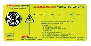
## **Thru-Panel Voltage** _**Voltage**_ **LOGO** _**Vision**_ **® Verification Solutions Data Sheet**

**==> picture [819 x 231] intentionally omitted <==**

**----- Start of picture text -----**<br>
DANGERSAFETY PROCEDURES STILL APPLY.TEST BEFORE TOUCHING.    VOLTAGE IF FLASHING DANGER VOLTAGE VOLTAGE PRE-TEST POINTS<br>L1 L2 L3<br>Manufacturers' Non-Contact Voltage Detector (NCVD) and Voltage Indicator<br>(VI) Procedures Apply. Procedure: 1.) Verify proper operation of VI.R-1A0033W-NPLPH (9.0 X 3.0)<br>2.) Verify NCVD to known voltage source.<br>3.) Open isolator.<br>4.) Verify NO flashing LEDs on VI.<br>_— — _—— os PRODUCTS, INCGRACEE N G I N E E R E D WWW.GRACE-ENG.COM Follow Safety ProceduresRead instructions before installing _— WARNING! 5.) Insert NCVD into bottom of recess & test ALL points.     6.) Re-Verify NCVD to known voltage source.7.) Upon completion of work, close isolator and veify proper operation of VI. ~ ®<br>Meter VoltageVision® (R-3W) ChekVolt®/NCVD (R-1A) DANGERSAFETY PROCEDURES STILL APPLY.TEST BEFORE TOUCHING.    VOLTAGE IF FLASHING DANGER VOLTAGE VOLTAGE PRE-TEST POINTS<br>Purpose: Multi-function Voltage Only  Voltage Only rs ne<br>Powered by: Batteries Line Voltage  Passive/Batteries L1 L2 L3<br>POWER = a —<br># Phases: Single 3-Phase  3-Phase/Single (VI) Procedures Apply.Manufacturers' Non-Contact Voltage Detector (NCVD) and Voltage Indicator<br>Hardwired to (3) Phase: NO YES  YES      2.) Verify NCVD to known voltage source. Procedure:      1.) Verify proper operation of VI.R-1A0033W-NPLPH (9.0 X 3.0) MM,este. mo<br>   Hardwired to Ground:Thru-Door: NONO YES YES   NOYES on PRODUCTS, INCGRACEE N G I N E E R E D WWW.GRACE-ENG.COM Follow Safety ProceduresRead instructions before installing WARNING! __      6.) Re-Verify NCVD to known voltage source.     7.) Upon completion of work, close isolator and veify proper operation of VI.     5.) Insert NCVD into bottom of recess & test ALL points.          3.) Open isolator.4.) Verify NO flashing LEDs on VI. isba<br>Indication: Digital Visual  Visual/Audible R-1A0033W-NPLPH<br>Physical Action: YES NO YES<br>    “Live-Dead-Live” Verified: YES NO  YES<br>**----- End of picture text -----**<br>


## **‘Functional’ Voltage Labeling**

The ability to identify, verify and locate every voltage source from the outside of electrical panels greatly reduces electrical risks. The R-1A0033W-NPLPH shown here shows how all these critical electrical safety concepts work together to elevate electrical safety and reduce risk.

Electrical safety requires voltage source labeling on the outside electrical enclosures to inform personnel how much electrical energy is contained within the system.  A ‘functional’ voltage label provides personnel with the ability to check the state of each source. Once maintenance personnel access the inside of the enclosure, these devices also point to the physical connection of the voltage source.

The NFPA 70e Annex G describes the LIVE-DEAD-LIVE procedure used to verify a voltage testing device as 1) verify voltage tester to a known ’LIVE’ source, 2) test for voltage source to insure that it is DEAD, and 3) re-verify voltage tester to another ‘LIVE’ source.

**==> picture [249 x 86] intentionally omitted <==**

**----- Start of picture text -----**<br>
L2 f e) O s L3 R-3W Features:<br>L1POWER      ?  Redundancy (2) LED’s/phase<br>DANGER      ?  40-750VAC / 30-1000VDC<br>     ?  Phase Insensitive<br>     ?  UL Listed for Type 4X<br>     ?  30mm Pushbutton or Pilot Hole<br>     ?  Potted Construction with 6’ Leads<br>L3 L3<br>**----- End of picture text -----**<br>


## **R-1A Features:**

? 600Volt Rating ? Integral 6’ Lead Wire ? UL 4 Listed for Type 4/4X ? ½” Mounting Hole

**==> picture [12 x 5] intentionally omitted <==**

**----- Start of picture text -----**<br>
Fuse<br>**----- End of picture text -----**<br>


The NFPA 70E states that the following principles are foundational to insuring a zero energy state:

## **Mechanical Lock-out/Tag-out (LOTO)**

Raw electrical energy can instantaneously cause shock or burn injuries to people. Not to mention that arc flash explosions can seriously damage equipment and cause downtime. A simple task like an electrician checking voltage is a leading cause of arc flash. Electricity is a lot safer when it is confined within a mechanical system just due to system design.

**all sources of electrical energy. [1]** The R-3W or R-1A installed will locate each source.

**==> picture [224 x 71] intentionally omitted <==**

**----- Start of picture text -----**<br>
The ChekVolt® R-1A is a UL-listed passive<br>device used to present a voltage source to the<br>outside of an electrical enclosure so that a<br>Non-Contact Voltage Detector (NCVD) can be  UL TYPE 4, 4X, 12<br>used to check for AC voltage.  C ® L US<br>LISTED<br>  3JZC<br>**----- End of picture text -----**<br>


**ally contact voltage detector to the electrical energy. [2]** The R-3W is hardwired to the source. **tween each phase and phase to ground.[3]** The R-3W checks voltage between phase-phase-ground. **voltage detector before and after use.[4]** A NCVD can be verified before and after each use.

The VoltageVision® R-3W is a UL-listed permanently mounted ‘voltmeter’ that monitors both AC and DC voltage between each phase and phase-to-ground.  When a phase is lost the LED's corresponding to that **UL TYPE 4X** phase will go dim giving a visual indication C outside the panel of a problem. Z OFLISTED UL File: E256847IND. CONT. EQ. 496Y

> **[2]** The R-3W is hardwired to the source.

A mechanical LOTO procedure isolates all energy sources before work begins on the piece of equipment. Some LOTO procedures put electricians at risk in order to verify zero voltage of the system.

Employers are responsible to train employees in selecting and properly using a voltage detector.[2]  It is also the responsibility of employers to provide a written lock-out/tag-out procedure and train employees on that procedures[5]. Follow manufacturer's instructions when using a noncontact voltage detector.  All other safety procedures apply.

**Now, you can purchase ChekVolt® and VoltAlert™ together!**

While 100% electrical isolation is beneficial for mechanical LOTO, it is not required to make a system mechanically safe. For example, a three phase motor rotates only when it receives enough current and the correct voltage on all three phases. The control systems also determines when a motor starts and stops. Either the R-3W or R-1A(s) used in conjunction with proper procedures offers a means to verify the electrical energy state for mechanical maintenance.  Therefore, no longer is an electrician put at risk to physically verify a zero electrical energy state prior to maintenance.

VoltAlert™ by Fluke is a quick and inexpensive way to check for the presence of live voltage through the panel door when used in conjunction with ChekVolt® by Grace Engineered Products. Also known as voltage wands, sticks, “power sniffers” or pens, they clip into a shirt pocket and “chirp” or glow when they detect voltage on exposed conducting parts or through insulation.

## NFPA 70E 2009 Edition references

**[1]** Annex G 6.1, **[2]** 110.6 (D)(4)(e), **[3]** 120.1(5), **[4]** 120.2(F)(2)(f)(1), Annex G 3.4, **[5]** 120.2(C)(2)

VoltAlert™ is designed for non-contact, live-not-live voltage detection on electrical circuits ranging from 90VAC to 1000VAC.  VoltAlert™ is powered by 2 AAA batteries (included) with a typical life of greater than one year, which gives 24/7, 365 days of added user protection.

**Please check out our application videos online by visiting www.graceport.com!**

**RoHS**

**==> picture [27 x 8] intentionally omitted <==**

**----- Start of picture text -----**<br>
(pending)<br>**----- End of picture text -----**<br>


**5001 Tremont Avenue Davenport, IA  52807 (800) 280-9517     Fax: (563) 386-9639** _**www.Graceport.com**_

**==> picture [276 x 26] intentionally omitted <==**

**----- Start of picture text -----**<br>
Voltage LOGO Vision ®<br>®<br>**----- End of picture text -----**<br>


**Data:ComboUnit:7/2009** © 2009 Grace Engineered Products, Inc. ChekVolt® is a Registered Trademark of Grace Engineered Products, Inc

**==> picture [1156 x 565] intentionally omitted <==**

**----- Start of picture text -----**<br>
Complete R-3W/R-1A Combination Kits The ChekVolt®, a non-contact voltage portal, reduces arc flash      The VoltageVision® (R-3W) is a reliable tool that helps<br>With Fluke 1AC NCVD  Size in  Mounting risk while increasing electrical safety and productivity by  answer the question, ‘Is there voltage?’.  Typically hardwired to<br>Without Fluke 1AC Pen, and a FREE Single- inches [mm] D -Door/Side Includes Qty    providing maintenance personnel a no-touch voltage portal on  the load side of the disconnect or circuit breaker, the<br>NCVD Pen point ChekVolt® and Label Nameplate Only W        H F -Flange R-3W’s     R-1A’s the outside of grounded metallic electrical enclosures.  The  VoltageVision® (R-3W) flashes whenever hazardous voltage is<br>R-1A0033W-NPLPH R-1A0033W-NPLPH-J R-LPMA 9.0[228.6]   4.0[101.6] D 1 3 ChekVolt® interface, installed on  present in any individual phase.<br>R-1A0033W-NPLPF R-1A0033W-NPLPF-J R-LPMA-F 1.9[47.0]    14.0[355.6] F 1 3 an electrical panel, allows       After disconnecting power to an enclosure, electricians can<br>R-1A003-LPH R-1A003-LPH-J R-LPH-L 6.0[152.4]  3.0[76.2] D 3 maintenance people to use any  pre-verify voltage isolation while the enclosure door is safely<br>R-1A003-LPF R-1A003-LPF-J R-LPH-F 1.9[47.0]    11 .0[278.4] F 3 non-contact voltage detector pen  closed.  The risk of  arc flash  is reduced because electricians<br>R-1A3W-LPB R-1A3W-LPB-J R-LPB 6.0[152.4]  3.0[76.2] D 1 1 to check line voltage before and  know if there is power inside the enclosure before re-verifying<br>R-1A3W-LPBF R-1A3W-LPBF-J R-LPB-F 1.9[47.0]    9.5 241.3][ F 1 1 after they open the main  isolation with a meter.<br>R-1A-LPA R-1A-LPA-J R-LPA-L 3 0[76.2]    3.0[76.2] . D 1 disconnect.  The ability to pre-      The VoltageVision® (R-3W) is unmatched in its reliability due<br>R-3W-L-KIT R-3W-L 3 0[76.2]    2.4[59.7] . D 1 verify electrical isolation before  to its dual redundant circuitry and no separate power supply.<br>R-3W-F-KIT R-3W-NP-F 1.9[47.0]    3.5 88.9][ F 1 opening a panel puts an  VoltageVision® (R-3W) gets its power from the same voltage<br>additional safety measure between electricians and hazardous  that it indicates!  Ask this question:  Can you live without it?<br>PRE-TEST POINT120 VOLT SEPARATE VOLTAGE  A DANGER VOLTAGEFollow Safety Procedures Read Instructions VOLTAGE IF FLASHING _ DANGER VOLTAGE(3-PHASE) Follow Safety ProceduresRead instructions before installingWARNING! DANGER SAFETY PROCEDURES STILL APPLY.TEST BEFORE TOUCHING.    VOLTAGE IF FLASHING DANGER VOLTAGE VOLTAGE PRE-TEST POINTS SAFETY PROCEDURES BEFORE TOUCHING. DANGER  IF FLASHING STILL APPLY.  VOLTAGETEST voltage.  The standard yellow name labels (as seen on back) help remind personnel to pre-verify every voltage point before accessing the panel interior. FEATURES:      ?  Redundant Circuitry / Long Life LED's<br>Procedure                       Specifications Apply CONTROL :  Non Contact Voltage Detector (NCVD)  ® L1 L2 L3 Follow Safety ProceduresRead instructions before installingWARNING!      ?     ?  Potted Construction with 6' Leads 40-750VAC / 30-1000VDC<br>   3.) Insert NCVD    4.) Re-verify NCVD to known voltage source.    1.) Verify NCVD to known voltage source.   2.) Open isolator.into bottom of recess & test Cc. . VOLTAGE IF FLASHING(3-PHASE) Grace Engineered Products, Inc.R-LPB , ecc Procedures: Voltage Indicator (VI) Procedures Apply.Manufacturers' Non-Contact Voltage Detector (NVCD) and cr y FEATURES:      ?  Phase Insensitive ww<br>Part #: R-LPB 120 VAC SEPARATE CONTROLVOLTAGE PRE-TEST POINT Follow Safety       2).  Verify NCVD to known voltage source.     3).  Open Isolator.     4).  Verify NO Flashing LEDs on VI.     5).  Insert NCVD into bottom of recess & test ALL points.1).  Verify proper operation of VI.      ?     ?  Integral 6’ lead wire Installs in a ½” hole for easy installation       ?     ?  30mm Pushbutton or Pilot Hole High Surge Immunity<br>DANGERSAFETY PROCEDURES STILL APPLY.TEST BEFORE TOUCHING.    VOLTAGE IF FLASHING TESTVOLTAGESAFETY PROCEDURESDANGERBEFORE TOUCHING.STILL APPLY.IF FLASHING Manufacturers' Non-Contact Voltage Detector (NVCD) and Voltage Indicator (VI)     Procedures Read InstructionsPRODUCTS, INCGRACEE N G I N E E R E D WWW.GRACEPORT.COM Part #:  R-LPMAFollow Safety ProceduresRead instructions before installingWARNING!      7).  Upon completion of work, close isolator and verify proper operation of VI.     6).  Re-Verify NCVD to known voltage source. Part #:  R-LPMA VOLTAGE PRE-TEST POINTSDANGER VOLTAGE L1 APPLICATIONS:      ?     ?  Rugged polycarbonate construction for safety UV outdoor rated so you can mount it anywhere      ? APPLICATIONS:  UL Type 4X Listed<br>Part#: R-3W-LPRODUCTS, INCGRACEE N G I N E E R E D WWW.GRACE-ENG.COM Read instructions    WARNING!before installing Follow Safety ProceduresRead instructions before installingWARNING! Procedures Apply.Procedures:1).  Verify proper       operation of VI.2).  Verify NCVD to       known voltage       source.3).  Open Isolator.4).  Verify NO Flashing  L1 DANGER VOLTAGE L2 VOLTAGE PRE-TEST POINTS L3 VOLTAGE PRE-TEST POINTSDANGER VOLTAGEFollow Safety ProceduresRead instructions before installingWARNING! L1 L2      ?     ?     ?  Frequently Accessed Panels Circuit Breaker Disconnects - No Visible Blades High Energy Panels (NFPA 70e Category III and IV)      ?     ?     ?  Frequently Accessed Panels High Energy Panels (NFPA 70e Category III and IV) Circuit Breaker Disconnects - No Visible Blades<br>[_] Part #: R-3W-L le! Part#: R-3W-NP-F2PRODUCTS, INCGRACEE N G I N E E R E D WWW.GRACEPORT.COM       LEDs on VI.5).  Insert NCVD into       bottom of recess &       test ALL points.6).  Re-Verify NCVD to       known voltage       source.7). Upon completion  Follow Safety    ProceduresGrace Engineered Products, Inc. ec o  Read InstructionsR-LPH ® s      3.) Insert NCVD  Procedure:      2.) Open isolator.1.) Verify 4.) Re-verify NCVD to known voltage source.  [—] NCVDNon Contact Voltage Detector (NCVD) Specifications Apply to known voltage source.into bottom of recess & test ALL  c points. i, enc      ?     ?  Panels with Multiple Power Sources Mechanical LOTO: Indicating Zero Energy<br>Part#: R-3W-NP-F      of work, close isolator  L3<br>     and verify proper      operation of VI. Part #: R-LPH L2<br>Grace Engineered Products, Inc.R-LPB-F ® DANGER VOLTAGE<br>— Part #: R-LPB-F   VOLTAGE PRE-TEST  — POINT Cc Follow Safety    ProceduresGrace Engineered Products, Inc. c  Read InstructionsR-LPA® ic L3 Procedures Apply.and Voltage Indicator (VI) Manufacturers' Non-Contact Voltage Detector (NVCD)  Application Story Modine Manufacturing Company of Racine, Wisconsin takes a  voltage inside the main cabinet without the need to dawn<br>A New and Interesting Application...    4.) Re-verify NCVD to known voltage source.    3.) Insert NCVD    2.) Open isolator. Procedure:                       (NCVD) Specifications Apply   1.) Verify NCVD to known voltage source.Non Contact Voltage Detector into bottom of recess & test. Procedures:1).  Verify proper       operation of VI.2).  Verify NCVD to       known voltage       source.3).  Open Isolator. more than 50 of their external disconnects with a combination of proactive approach to safety.  That's why they have equipped  additional PPE for the procedure.  This saves us the time it takes to retrieve, put on, and return the appropriate level of PPE to retrieve, put on, and return the appropriate level of PPE<br>First, mounted either in the flange or on the side wall of a non-The new vertical Combination Unit featuring VoltageVision® and ChekVolt® affords the end user two very important advantages.   Part #: R-LPA-L Manufacturers' Non-Contact Voltage Detector (NVCD) and Voltage Indicator (VI) Procedures Apply.Procedures:1).  Verify proper       operation of VI.2).  Verify NCVD to       known voltage       source.3).  Open Isolator.       known voltage       source.7). Upon completion      of work, close isolator      and verify proper      operation of VI.4).  Verify NO Flashing       LEDs on VI.5).  Insert NCVD into       bottom of recess &       test ALL points.6).  Re-Verify NCVD to  ChekVolt® and VoltageVision®, known by part number R-1A0033W-NPLPH.  John Hauke, Senior Principle Controls Engineer explains, "the  required to verify and work inside a main cabinet that has live voltage on the line side of an internal disconnect."voltage on the line side of an internal disconnect."<br>flange enclosure (see Images 1 and 2), this installation keeps the  4).  Verify NO Flashing       LEDs on VI.5).  Insert NCVD into  a Part#: R-LPMA-FPRODUCTS, INCGRACEE N G I N E E R E D WWW.GRACE PORT .COM disconnect system is mounted externally to the main panel<br>      bottom of recess &<br>line voltage detectors off the door and eliminates long wire        test ALL points.6).  Re-Verify NCVD to  Part#: R-LPMA-F ensuring that no power exists within the cabinet after the<br>      known voltage<br>      source. disconnect has been locked out.  The presence (or absence) of<br>running around the door hinges.  Second, vertical mounting of  7). Upon completion      of work, close isolator<br>     and verify proper      operation of VI. voltage is visually verified through the use of the VoltageVision®  (meee | 8 TR CAN ROGIER TEST [tears][ *)]<br>these assemblies also limits the wiring distance to the panel<br>Grace Engineered Products, Inc.R-LPH-F ® R-3W product and then we verify proper operation of the R-3W by<br>disconnect or circuit breaker and is a simple and safer installation.<br>Part #: R-LPH-F<br>**----- End of picture text -----**<br>


voltage inside the main cabinet without the need to dawn additional PPE for the procedure.  This saves us the time it takes to retrieve, put on, and return the appropriate level of PPE to retrieve, put on, and return the appropriate level of PPE required to verify and work inside a main cabinet that has live voltage on the line side of an internal disconnect."voltage on the line side of an internal disconnect."

The new vertical Combination Unit featuring VoltageVision® and ChekVolt® affords the end user two very important advantages.  ChekVolt® affords the end user two very important advantages. First, mounted either in the flange or on the side wall of a non-The new vertical Combination Unit featuring VoltageVision® and ChekVolt® affords the end user two very important advantages. flange enclosure (see Images 1 and 2), this installation keeps the line voltage detectors off the door and eliminates long wire running around the door hinges.  Second, vertical mounting of these assemblies also limits the wiring distance to the panel disconnect or circuit breaker and is a simple and safer installation.

John Hauke, Senior Principle Controls Engineer explains, "the disconnect system is mounted externally to the main panel ensuring that no power exists within the cabinet after the disconnect has been locked out.  The presence (or absence) of voltage is visually verified through the use of the VoltageVision® R-3W product and then we verify proper operation of the R-3W by checking all three phases with a non-contact voltage detection pen at each ChekVolt® port.  The Grace faceplates are an added visual aid to explain the proper use of the devices.  This system allows our maintenance staff to quickly and confidently verify zero

**Reminder...Don’t forget the ‘dash J’!**

**==> picture [102 x 16] intentionally omitted <==**

**----- Start of picture text -----**<br>
R-1A0033W-NPLPH<br>**----- End of picture text -----**<br>


**==> picture [230 x 111] intentionally omitted <==**

**----- Start of picture text -----**<br>
We now offer with all the ChekVolt® packages the option<br>to get VoltAlert™ by Fluke!  You can order them by<br>adding ‘-J’ to your part number (see top of page for part<br>DANGERSAFETY PROCEDURES STILL APPLY.TEST BEFORE TOUCHING.    VOLTAGE IF FLASHING DANGER VOLTAGE VOLTAGE PRE-TEST POINTS number listing).  These<br>L1 L2 L3 NCVD pens “chirp” or<br>PRODUCTS, INCGRACEE N G I N E E R E D WWW.GRACE-ENG.COM B a Follow Safety ProceduresRead instructions before installing WARNING! n (VI) Procedures Apply.Manufacturers' Non-Contact Voltage Detector (NCVD) and Voltage Indicator  Procedure:      1.) Verify proper operation of VI.     2.) Verify NCVD to known voltage source.     3.) Open isolator.     5.) Insert NCVD into bottom of recess & test ALL points.          6.) Re-Verify NCVD to known voltage source.     7.) Upon completion of work, close isolator and veify proper operation of VI.4.) Verify NO flashing LEDs on VI.R-1A0033W-NPLPH (9.0 X 3.0) we glow when they detect voltage on exposed<br>conducting parts or<br>R-1A0033W-NPLPH-J<br>through insulation!<br>**----- End of picture text -----**<br>


## **Part #: R-1A3W-LPB**

Use VoltageVision® (R-3W) with our ChekVolt™ (R-1A).  ChekVolt™ utilizes a non-contact voltage detector pen to locate voltage isolation.  Both ChekVolt™ and VoltageVision® can be ordered separately or in this kit! (Faceplate is 3"W x 6"H). **Kit includes: one ChekVolt™, one VoltageVision®, and a faceplate!**

**==> picture [45 x 12] intentionally omitted <==**

**----- Start of picture text -----**<br>
Image 1<br>**----- End of picture text -----**<br>


**==> picture [46 x 12] intentionally omitted <==**

**----- Start of picture text -----**<br>
Image 2<br>**----- End of picture text -----**<br>
Updated at February 9, 2023
About Novapart
Novapart is a B2B electronic component broker specialising in stock shortages and cost reduction. We source hard-to-find parts and identify compliant alternatives across a catalogue of 410,000+ components from 500+ manufacturers.
Learn more →Stock Shortage Specialist
When a component is unavailable, discontinued or has an unacceptable lead time, we tap into our network of vetted European and Asian distributors to source what you need — without compromising on quality or traceability.
Request a quote →Compliant Alternatives
We identify pin-to-pin, electrically equivalent substitutes that meet the same certifications (RoHS, AEC-Q100, REACH) as your original specification — validated against datasheets, not just part numbers. Often at a lower cost.
BOM Analysis service →