


PYP18
Relay Accessory, DIN Rail, PY14 Relay Sockets
- Manufacturer: OMRON INDUSTRIAL AUTOMATION
- Product type: Other Relay Accessories
- Accessory Type:DIN Rail; For Use With:PY14 Relay Sockets
- SVHC: No SVHC (17-Dec-2014)
- For Use With: PY14 Relay Sockets
- Accessory Type: DIN Rail
| Delivery and price | |
|---|---|
| Units per pack | 10 |
| Price | 9.81 € |
| Current stock | 10+ |
| Lead time | 30 days |
## **General-purpose Relay MY New model**
## **Versatile and Function-filled Miniature Power Relay for Sequence Control and Power Switching Applications**
- Many variations possible through a selection of operation indicators (mechanical and LED indicators), test button, built-in diode and CR (surge suppression), bifurcated contacts, etc.
- Arc barrier standard on 4-pole Relays.
- Dielectric strength: 2,000 VAC (coil to contact)
- Environment-friendly cadmium-free contacts.
- Safety standard approvals obtained.
- Wide range of Sockets (PY, PYF Series) and optional parts are available.
**==> picture [24 x 15] intentionally omitted <==**
**----- Start of picture text -----**<br>
LR<br>**----- End of picture text -----**<br>
- Max. Switching Current: 2-pole: 10 A, 4-pole: 5 A
- Built-in mechanical operation indicator.
- Provided with nameplate.
## **Orderin Information g**
## ■ **Relays**
## **Standard Coil Polarity**
|**Type**|**Contact form**|**Plug-in socket/Solder terminals**|**Plug-in socket/Solder terminals**|**Without LED indicator**|
|---|---|---|---|---|
|||**Standard with LED indicator**|**With LED indicator and test**<br>**button**||
|Standard|DPDT|MY2N|MY2IN|MY2|
||4PDT|MY4N|MY4IN|MY4|
||4PDT (bifurcated)|MY4ZN|MY4ZIN|MY4Z|
|With built-in diode<br>(DC only)|DPDT|MY2N-D2|MY2IN-D2|---|
||4PDT|MY4N-D2|MY4IN-D2|---|
||4PDT (bifurcated)|MY4ZN-D2|MY4ZIN-D2|---|
|With built-in CR<br>(220/240 VAC, 110/120 VAC<br>only)|DPDT|MY2N-CR|MY2IN-CR|---|
||4PDT|MY4N-CR|MY4IN-CR|---|
||4PDT (bifurcated)|MY4ZN-CR|MY4ZIN-CR|---|
## **Reverse Coil Polarity**
|**Type**|**Contact form**|**Plug-in socket/Solder terminals**|**Plug-in socket/Solder terminals**|
|---|---|---|---|
|||**With LED indicator**|**With LED indicator and test button**|
|Standard (DC only)|DPDT|MY2N1|MY2IN1|
||4PDT|MY4N1|MY4IN1|
||4PDT (bifurcated)|MY4ZN1|MY4ZIN1|
|With built-in diode<br>(DC only)|DPDT|MY2N1-D2|MY2IN1-D2|
||4PDT|MY4N1-D2|MY4IN1-D2|
||4PDT (bifurcated)|MY4ZN1-D2|MY4ZIN1-D2|
**Note:** When ordering, add the rated coil voltage and “(s)” to the model number. Rated coil voltages are given in the coil ratings table.
Example: MY2 6VAC (S) —— New model Rated coil voltage
General-purpose Relay **MY New model**
49
## ■ **Accessories (Order Separately)**
## **Sockets**
|**Poles**|**Front-mounting**<br>**Socket (DIN-track/**<br>**screw mounting)**|**Back-mounting Socket**|**Back-mounting Socket**|**Back-mounting Socket**|**Back-mounting Socket**|**Back-mounting Socket**|
|---|---|---|---|---|---|---|
|||**Solder terminals**||**Wire-wrap terminals**||**PCB terminals**|
|||**Without clip**|**With clip**|**Without clip**|**With clip**||
|2|PYF08A-E<br>PYF08A-N|PY08|PY08-Y1|PY08QN<br>PY08QN2|PY08QN-Y1<br>PY08QN2-Y1|PY08-02|
|4|PYF14A-E<br>PYF14A-N|PY14|PY14-Y1|PY14QN<br>PY14QN2|PY14QN-Y1<br>PY14QN2-Y1|PY14-02|
## **Socket Hold-down Clip Pairing**
|**Relay type**|**Poles**|**Front-connecting Socket (DIN-track/**<br>**screw mounting)**|**Front-connecting Socket (DIN-track/**<br>**screw mounting)**|**Back-connecting Socket**|**Back-connecting Socket**|**Back-connecting Socket**|**Back-connecting Socket**|
|---|---|---|---|---|---|---|---|
|||||**Solder/Wire-wrap terminals**||**PCB terminals**||
|||**Socket**|**Clip**|**Socket**|**Clip**|**Socket**|**Clip**|
|Without 2-pole test<br>button|2|PYF08A-E<br>PYF08A-N|PYC-A1|PY08(QN)|PYC-P<br>PYC-P2|PY08-02|PYC-P<br>PYC-P2|
||4|PYF14A-E<br>PYF14A-N||PY14(QN)||PY14-02||
|2-pole test button|2|PYF08A-E<br>PYF08A-N|PYC-E1|PY08(QN)|PYC-P2|PY08-02|PYC-P2|
## **Mounting Plates for Sockets**
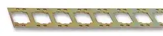
**Note:** PYP-18 and PYP-36 can be cut into any desired length in accordance with the number of Sockets.
## **Track and Accessories**
## **S ecifications p**
## ■ **Coil Ratings**
> **Note: 1.** The rated current and coil resistance are measured at a coil temperature of 23°C with tolerances of +15%/–20% for rated currents and ±15% for DC coil resistance.
> **2.** Performance characteristic data are measured at a coil temperature of 23°C.
> **3.** AC coil resistance and impedance are provided as reference values (at 60 Hz).
> **4.** Power consumption drop was measured for the above data. When driving transistors, check leakage current and connect a bleeder resistor if required.
> **5.** Rated voltage denoted by “*” will be manufactured upon request. Ask your OMRON representative.
General-purpose Relay **MY New model**
50
## ■ **Contact Ratings**
|**Item**|**2-pole**|**2-pole**|**4-pole**|**4-pole**|**4-pole (bifurcated)**|**4-pole (bifurcated)**|
|---|---|---|---|---|---|---|
||**Resistive load**<br>**(cos**φ**= 1)**|**Inductive load**<br>**(cos**φ**= 0.4, L/R = 7 ms)**|**Resistive load**<br>**(cos**φ**= 1)**|**Inductive load**<br>**(cos**φ**= 0.4, L/R = 7 ms)**|**Resistive load**<br>**(cos**φ**= 1)**|**Inductive load**<br>**(cos**φ**= 0.4, L/R = 7 ms)**|
|Rated load|5A, 250 VAC<br>5A, 30 VDC|2A, 250 VAC<br>2 A, 30 VDC|3 A, 250 VAC<br>3 A, 30 VDC|0.8 A, 250 VAC<br>1.5 A, 30 VDC|3 A, 250 VAC<br>3 A, 30 VDC|0.8 A, 250 VAC<br>1.5 A, 30 VDC|
|Carrycurrent|10 A (see note)||5 A (see note)||||
|Max. switching<br>voltage|250 VAC<br>125 VDC||250 VAC<br>125 VDC||||
|Max. switching<br>current|10 A||5 A||||
|Max. switching<br>power|2,500 VA<br>300 W|1,250 VA<br>300 W|1,250 VA<br>150 W|500 VA<br>150 W|1,250 VA<br>150 W|500 VA<br>150 W|
|Failure rate<br>(reference value)|5 VDC, 1 mA||1 VDC, 1 mA||1 VDC, 100µA||
**Note:** Don’t exceed the carry current of a Socket in use. Please see page 57.
## ■ **Characteristics**
|■**Characteristics**||
|---|---|
|**Item**|**All Relays**|
|**Contact resistance**|100 mΩmax.|
|**Operate time**|20 ms max.|
|**Release time**|20 ms max.|
|**Max. operating frequency**|Mechanical:<br>18,000 operations/hr<br>Electrical:<br>1,800 operations/hr (under rated load)|
|**Insulation resistance**|1,000 MΩmin. (at 500 VDC)|
|**Dielectric strength**|2,000 VAC, 50/60 Hz for 1.0 min (1,000 VAC between contacts of same polarity)|
|**Vibration resistance**|Destruction:<br>10 to 55 to 10 Hz, 0.5 mm single amplitude (1.0 mm double amplitude)<br>Malfunction:<br>10 to 55 to 10 Hz, 0.5 mm single amplitude (1.0 mm double amplitude)|
|**Shock resistance**|Destruction:<br>1,000 m/s2<br>Malfunction:<br>200 m/s2|
|**Endurance**|See the following table.|
|**Ambient temperature**|Operating: –55°C to 70°C (with no icing)|
|**Ambient humidity**|Operating: 5% to 85%|
|**Weight**|Approx. 35 g|
**Note:** The values given above are initial values.
## ■ **Endurance Characteristics**
|■**Endurance**|**Characteristics**||
|---|---|---|
|**Pole**|**Mechanical life (at 18,000 operations/hr)**|**Electrical life**<br>**(at 1,800 operations/hr under rated load)**|
|2-pole|AC:50,000,000 operations min.<br>DC:100,000,000 operations min.|500,000 operations min.|
|4-pole||200,000 operations min.|
|4-pole (bifurcated)|20,000,000 operations min.|100,000 operations min.|
General-purpose Relay **MY New model**
51
## ■ **Approved Standards**
## **VDE Recognitions (File No. 112467UG, IEC 255, VDE 0435)**
|**No. of poles**|**Coil ratings**|**Contact ratings**|**Operations**|
|---|---|---|---|
|2|6, 12, 24, 48/50, 100/110<br>110/120, 200/220,<br>220/240 VAC<br>6, 12, 24, 48, 100/110,<br>125 VDC|10 A, 250 VAC (cosφ=1)<br>10 A, 30 VDC (L/R=0 ms)|10 x 103|
|4||5 A, 250 VAC (cosφ=1)<br>5 A, 30 VDC (L/R=0 ms)|100 x 103<br>MY4Z AC; 50 x 103|
## **UL508 Recognitions (File No. 41515)**
|**No. ofpoles**|**Coil ratings**|**Contact ratings**|**Operations**|
|---|---|---|---|
|2|6 to 240 VAC<br>6 to 125 VDC|10 A, 30 VDC (General purpose)<br>10 A, 250 VAC(Generalpurpose)|6 x 10³|
|4||5 A, 250 VAC (General purpose)<br>5 A, 30 VDC(Generalpurpose)||
|**CSA C22.2 No. 14 Listings (File No. LR31928)**||||
|||||
|**No. ofpoles**|**Coil ratings**|**Contact ratings**|**Operations**|
|2|6 to 240 VAC<br>6 to 125 VDC|10 A, 30 VDC<br>10 A, 250 VAC|6 x 10³|
|4||5 A, 250 VAC (Same polarity)<br>5 A, 30 VDC(Samepolarity)||
|**IMQ (File No. EN013 to 016)**||||
|**No. of poles**|**Coil ratings**|**Contact ratings**|**Operations**|
|2|6, 12, 24, 48/50, 100/110<br>110/120, 200/220,<br>220/240 VAC<br>6, 12, 24, 48, 100/110,<br>125 VDC|10 A, 30 VDC<br>10 A, 250 VAC|10 x 103|
|4||5 A, 250 VAC<br>5 A, 30 VDC|100 x 103<br>MY4Z AC; 50 x 103|
## **LR Recognitions (File No. 98/10014)**
|**No. ofpoles**|**Coil ratings**|**Contact ratings**|**Operations**|
|---|---|---|---|
|2|6 to 240 VAC<br>6 to 125 VDC|10 A, 250 VAC (Resistive)<br>2 A, 250 VAC (PF0.4)<br>10 A, 30 VDC (Resistive)<br>2 A, 30 VDC(L/R=7 ms)|50 x 103|
|4||5 A, 250 VAC (Resistive)<br>0.8 A, 250 VAC (PF0.4)<br>5 A, 30 VDC (Resistive)<br>1.5 A, 30 VDC(L/R=7 ms)|50 x 103|
## **SEV Listings (File No. 99.5 50902.01)**
|**No. of poles**|**Coil ratings**|**Contact ratings**|**Operations**|
|---|---|---|---|
|2|6 to 240 VAC<br>6 to 125 VDC|10 A, 250 VAC<br>10 A, 30 VDC|10 x 103|
|4||5 A, 250 VAC<br>5 A, 30 VDC|100 x 103<br>MY4Z AC; 50 x 103|
General-purpose Relay **MY New model**
52
## **MY4Z (Resistive Loads)**
## **MY4Z (Inductive Loads)**
**==> picture [422 x 156] intentionally omitted <==**
**----- Start of picture text -----**<br>
10000 ———_ ee ed 10000 T_T<br>5000 os 5000 ————<br>er |<br>3000 po 3000 rs ee ee<br>1000 a 1000 |__|<br>250 VAC<br>—_— |<br>500 500 30 VDC<br>300 300<br>— —— —— 30 VDC S————————————— 30 VDC<br>100 PO 30 VDC N S 100 7S——— 250 VAC<br>50 a 50 S S<br>30 e rn aeeee a eee 250 VAC neee 30 parr a 250 VAC<br>10 10<br>2 3 4 6 ) 0.5 7 1,5 2<br>Switching Current (A) Switching Current (A)<br>3 3<br>Endurance (x10 operations) Endurance (x10 operations)<br>**----- End of picture text -----**<br>
General-purpose Relay **MY New model**
54
## **Dimensions**
**Note:** All units are in millimeters unless otherwise indicated.
## **2-Pole Models**
**==> picture [136 x 66] intentionally omitted <==**
**----- Start of picture text -----**<br>
1.2-dia. x 2.2 long holes<br>28 max.<br>= e 8 (4.402)<br>36 max.<br>21.5 max.<br>**----- End of picture text -----**<br>
## **4-Pole Models**
**==> picture [145 x 74] intentionally omitted <==**
**----- Start of picture text -----**<br>
1.2-dia. x 2.2 long holes<br>28 max.<br>36 max.<br>21.5 max.<br>b a ,= (0.846)<br>**----- End of picture text -----**<br>
## **Models with Test Button**
**==> picture [77 x 65] intentionally omitted <==**
**----- Start of picture text -----**<br>
Test button<br>Nameplate 36 max.<br>an (1.417)<br>**----- End of picture text -----**<br>
General-purpose Relay **MY New model**
55
## **Terminal Arrangement/Internal Connections (Bottom View)**
**MY2 MY2N/MY2IN (AC Models)**
**MY2N/MY2IN MY2N-D2/MY2IN-D2 (DC Models) (DC Models Only)**
**MY2N-CR/MY2IN-CR MY2N1/MY2IN1 MY2N1-D2/MY2IN1-D2 (AC Models Only) (DC Models Only) (DC Models Only)**
**MY4(Z) MY4(Z)N/MY4(Z)IN MY4(Z)N/MY4(Z)IN MY4(Z)N-D/MY4(Z)IN-D2 (AC Models) (DC Models) (DC Models Only)**
**MY4(Z)N-CR/MY4(Z)IN-CR MY4(Z)N1/MY4(Z)IN1 MY4(Z)N1-D2/MY4(Z)IN1-D2 (AC Models Only) (DC Models Only) (DC Models Only)**
**Note:** The DC models have polarity.
General-purpose Relay **MY New model**
56
## **Socket for MY**
## **Track-mounted (DIN Track) Socket Conforms to VDE 0106, Part 100**
- Snap into position along continuous sections of any mounting track.
- Facilitates sheet metal design by standardized mounting dimensions.
- Design with sufficient dielectric separation between terminals eliminates the need of any insulating sheet.
## ■ **Safety Standards for Sockets**
|**Model**|**Standards**|**File No.**|
|---|---|---|
|PYF08A-E, PYF08A-N<br>PYF14A-E, PYF14A-N|UL508|E87929|
||CSA22.2|LR31928|
## **Back-connecting Sockets**
##
## ■ **Specifications**
|**Item**|**Pole**|**Model**|**Carry current**|**Dielectric withstand**<br>**voltage**|**Insulation resistance**<br>**(see note 2)**|
|---|---|---|---|---|---|
|Track-mounted<br>Socket|2|PYF08A-E|7 A|2,000 VAC, 1 min|1,000 MΩmin.|
|||PYF08A-N (see note 3)|7 A (see note 4)|||
||4|PYF14A-E|5 A|||
|||PYF14A-N (see note 3)|5 A (see note 4)|||
|Back-connecting<br>Socket|2|PY08(-Y1)|7 A|1,500 VAC, 1 min|100 MΩmin.|
|||PY08QN(-Y1)||||
|||PY08-02||||
||4|PY14(-Y1)|3 A|||
|||PY14QN(-Y1)||||
|||PY14-02||||
- **Note: 1.** The values given above are initial values.
**2.** The values for insulation resistance were measured at 500 V at the same place as the dielectric strength.
**3.** The maximum operating ambient temperature for the PYF08A-N and PYF14A-N is 55°C.
**4.** When using the PYF08A-N or PYF14A-N at an operating ambient temperature exceeding 40°C, reduce the current to 60%.
General-purpose Relay **MY New model**
57
## ■ **Dimensions**
**Note:** All units are in millimeters unless otherwise indicated.
|**Note:**All units are in millimeters unless otherwise indicated.|All units are in millimeters unless otherwise indicated.|||
|---|---|---|---|
|**Socket**|**Dimensions**|**Terminal arrangement/**<br>**Internal connections**<br>**(top view)**|**Mounting holes**|
|PYF08A-E|31 max.<br>23 max.<br>72 max.<br>Two, 4.2 x 5<br>mounting<br>holes<br>Eight, M3 x 8<br>sems screws<br>3.4<br>au<br>i<br>oO<br>a<br>4<br>rear<br>16.5<br>:||(TOP VIEW)<br>Two, M3, M4, or 4.5-dia. holes<br>**Note:**Track mounting is also<br>possible. Refer to page<br>12 for supporting tracks.<br>59+0.3<br>150.2|
|PYF08A-N<br><i|4<br>42<br>8<br>44<br>1<br>12<br>5<br>14<br>41<br>12<br>A2<br>14<br>11<br>9<br>A1<br>13<br>A2<br>14<br>PYF-08A-N<br>73<br>22 max.<br>67 max.<br>30 max.<br>~~Fo~~<br>om,<br>=|4<br>42<br>1<br>8<br>5<br>12<br>9<br>14<br>14<br>13<br>44<br>12<br>14<br>41<br>11<br>A2 A2 A1<br>J|18.7<br>3.0 dia.<br>3.5 dia. or M3<br>**Note:**Track mounting is also<br>possible. Refer to page<br>12 for supporting tracks.|
|PYF14A-E<br>ay|<br>ed|31 max.<br>29.5 max.<br>72 max.<br>Two, 4.2 x 5<br>mounting<br>holes<br>Fourteen, M3 x 8<br>sems screws<br>6<br>3.4<br>aaaael<br>tit)<br>i<br>nl<br>ak<br>16.5|oeGe<br>&|(TOP VIEW)<br>Two, M3, M4, or 4.5-dia. holes<br>**Note:**Track mounting is also<br>possible. Refer to page<br>12 for supporting tracks.<br>59403|
|PYF14A-N<br>—<br>meee 4<br>~~By~~|4<br>42<br>3<br>32<br>2<br>22<br>1<br>12<br>8<br>44<br>7<br>34<br>6<br>24<br>5<br>14<br>41<br>12<br>31<br>11<br>21<br>10<br>11<br>9<br>A1<br>13<br>A2<br>14<br>A2<br>14<br>PYF-14A-N<br>73<br>30 max.<br>67 max.<br>29.5 max.<br>P~~oee§~~<br>~~oo~~<br>~~By~~ |<br>lod<br>jo||4<br>3<br>2<br>1<br>8<br>7<br>6<br>5<br>12<br>11<br>10<br>9<br>14<br>14<br>13<br>42 32 22 12<br>44 34<br>24 14<br>41 31 21 11<br>A2 A2<br>A1<br>O<br>I<br>| ga ||26<br>Two, 4.5 dia. or M4<br>**Note:**Track mounting is also<br>possible. Refer to page<br>12 for supporting tracks.<br>||
General-purpose Relay **MY New model**
58
**==> picture [505 x 608] intentionally omitted <==**
**----- Start of picture text -----**<br>
Socket Dimensions Terminal arrangement/ Mounting holes<br>Internal connections<br>(bottom view)<br>PY08/PY08-Y1 (See note) Eight, 3 x 1.2 elliptical holes<br>an aaa por mp peen tense, x (aot '<br>i ag ee dd Rh 25.5 max. Ot<br>29.5 max.<br>20 max. 24 max.<br>42 max.<br>Note: The PY08-Y1 includes sections indicated by<br>dotted lines.<br>25.879<br>PY08QN/<br>PY08QN-Y1<br>(See note) 29.5 max.<br>rr i f ES | ar.4ath?<br>41.5 max. 22 max.<br>WP | { | 42 max. 27 25—| 24 max. © 2)<br>Ju? : : ® ©<br>Note: The PY08QN-Y1 includes sections<br>indicated by dotted lines.<br>PY08-02 0.3 fcteaa| 1.0 tof| camak<br>25.5 max.<br>29.5 max.<br>wa y Ele —_ f TP ess 2°<br>27° 16.5 max. 43 22 max. 2 a! 42 Eight, 1.3-dia. holes<br>PY14/PY14-Y1 (See note) Fourteen, 3 x 1.2 elliptical holes<br>25.5 max.<br>29.5 max.<br>eS" i Soded ae deenees dE] ia |<br>re {pros dee ||<br>\ | 27 +77 26<br>20 max. 24 max.<br>42 max.<br>Note: The PY14-Y1 includes sections indicated by<br>dotted lines.<br>PY14QN/ | |<br>PY14QN-Y1<br>ba (See note) Hd<br>29.5 max.<br>ie || =F a | ©0600<br>41.5 max.<br>\ A | Z 42 max. BI 25 ce 22 max. 0008<br>24 max.<br>Note: The PY14QN-Y1 includes sections<br>1) indicated by dotted lines.<br>PY14-02 i 1,0 a 7<br>Se, o3 SqqRt 25.5 max. : ttt<br>29.5 max.<br>FEEE ¥feeeg|<br>27H H+ 43 Lt 22 max. 2 6a (? = gi<br>16.5 max. cy Fourteen, 1.3-dia. holes<br>**----- End of picture text -----**<br>
**Note:** Use a panel with plate thickness of 1 to 2 mm for mounting the Sockets.
General-purpose Relay **MY New model**
59
## **Hold-down Clips**
## **PYC-A1**
**==> picture [109 x 104] intentionally omitted <==**
**----- Start of picture text -----**<br>
(2 pcs per set)<br>36.3<br>4.5<br>4.5 1.2<br>**----- End of picture text -----**<br>
**==> picture [90 x 114] intentionally omitted <==**
**----- Start of picture text -----**<br>
PYC-E1<br>(2 pcs per set)<br>36.3<br>5.75<br>4.25<br>4.5 [±][0.1]<br>**----- End of picture text -----**<br>
## **PYC-P**
## 5 coor
**==> picture [66 x 93] intentionally omitted <==**
**----- Start of picture text -----**<br>
5<br>29 max.<br>3.3<br>38.5<br>/<br>**----- End of picture text -----**<br>
## **PYC-P2**
28
10 ae
## **- Mounting Plates for Back connecting Sockets**
**==> picture [24 x 7] intentionally omitted <==**
**----- Start of picture text -----**<br>
PYP-1<br>**----- End of picture text -----**<br>
## **PYP-36**
**==> picture [64 x 12] intentionally omitted <==**
**----- Start of picture text -----**<br>
Two, 3.4-dia. holes<br>_ [3]<br>**----- End of picture text -----**<br>
72 elliptical holes
## t=1.6
## **PYP-18**
**==> picture [48 x 7] intentionally omitted <==**
**----- Start of picture text -----**<br>
72 elliptical holes<br>**----- End of picture text -----**<br>
General-purpose Relay **MY New model**
60
## **Tracks and Accessories**
## **Supporting Tracks**
## **PFP-50N/PFP-100N**
## **PFP-100N2**
**==> picture [324 x 160] intentionally omitted <==**
**----- Start of picture text -----**<br>
7.3±0.15<br>4.5<br>35±0.3 27±0.15<br>1<br>15 25 25 25 25 15 (5)<br>10 10<br>1000 (500) *<br>Note: The figure in the parentheses is for PFP-50N.<br>16<br>4.5<br>35±0.3 27 24 29.2<br>15 25 10 25 1000 25 10 25 15 1 1.5<br>**----- End of picture text -----**<br>
## **End Plate**
**==> picture [29 x 8] intentionally omitted <==**
**----- Start of picture text -----**<br>
PFP-M<br>**----- End of picture text -----**<br>
**==> picture [17 x 23] intentionally omitted <==**
**----- Start of picture text -----**<br>
50<br>11.5<br>**----- End of picture text -----**<br>
## **Spacer**
**PFP-S**
ALL DIMENSIONS SHOWN ARE IN MILLIMETERS. To convert millimeters into inches, multiply by 0.03937. To convert grams into ounces, multiply by 0.03527. In the interest of product improvement, specifications are subject to change without notice.
Cat. No. J111-E1-02
General-purpose Relay **MY New model**
61
Updated at June 7, 2026
With a legacy spanning over 80 years, Omron Industrial Automation is a globally recognized leader in the manufacture of advanced industrial control and automation components. Renowned for their reliability and engineering excellence, Omron delivers comprehensive solutions that enhance efficiency, machine safety, and precision across a wide range of manufacturing environments. Our extensive portfolio of Omron products is heavily focused on their industry-leading sensing and switching technologies. We offer a vast selection of sensors, excelling specifically in high-performance proximity sensors, light sensors, and temperature sensors. Complementing this range are robust switching solutions, featuring a deep inventory of power relays, solid-state relays, safety relays, and essential relay accessories designed for demanding operational requirements. Beyond sensing and switching, Omron is highly regarded for its precision automation and process control equipment. Our selection features highly accurate temperature controllers, versatile process controllers, and sophisticated panel displays and instrumentation. To support these fundamental systems, we also supply dependable Omron power supplies, notably AC/DC converters, alongside vital connectivity components like DIN rail terminal blocks to ensure secure, efficient, and complete industrial setups.
About Novapart
Novapart is a B2B electronic component broker specialising in stock shortages and cost reduction. We source hard-to-find parts and identify compliant alternatives across a catalogue of 410,000+ components from 500+ manufacturers.
Learn more →Stock Shortage Specialist
When a component is unavailable, discontinued or has an unacceptable lead time, we tap into our network of vetted European and Asian distributors to source what you need — without compromising on quality or traceability.
Request a quote →Compliant Alternatives
We identify pin-to-pin, electrically equivalent substitutes that meet the same certifications (RoHS, AEC-Q100, REACH) as your original specification — validated against datasheets, not just part numbers. Often at a lower cost.
BOM Analysis service →