
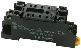


PYF08A-E
RELAY SOCKET
- Manufacturer: OMRON INDUSTRIAL AUTOMATION
- Product type: Relay Sockets
- No. of Pins: 8Pins
- Product Range: SUPER MY Series
- Current Rating: 7A
- Voltage Rating: 250VAC
- Socket Mounting: DIN Rail
- Socket Terminals: Screw
| Delivery and price | |
|---|---|
| Units per pack | 50 |
| Price | 5.99 € |
| Current stock | 10+ |
| Lead time | 30 days |
## **General-purpose Relay MY**

## **Versatile, Multi-featured, Miniature Power Relay for Sequence Control and Power Switching Applications**

- Models with lockable test buttons now available.

- Multiple features available, including operation indicators (mechanical and LED indicators), lockable test button, built-in diode and CR (surge suppression), bifurcated contacts, etc.

- Environment-friendly cadmium-free contacts.

- Wide range of Sockets (PY, PYF Series) and optional parts.

- Max. Switching Current: 2-pole: 10 A, 4-pole: 5 A

**==> picture [25 x 14] intentionally omitted <==**

**----- Start of picture text -----**<br>
LR<br>**----- End of picture text -----**<br>


- Provided with nameplate.

- RoHS Complaint.

## **Orderin Information g**

## I **Relays**

## **Standard Coil Polarity**

|**Type**<br>**Contact form**<br>**Model**<br>**Plug-in socket/solder terminals**<br>**Standard with LED**<br>**indicator**<br>**With LED indicator and**<br>**lockable test button**<br>**Without LED indicator**<br>Standard<br>DPDT<br>**MY2N**<br>**MY2IN**<br>**MY2**<br>4PDT<br>**MY4N**<br>**MY4IN**<br>**MY4**<br>4PDT (bifurcated)<br>**MY4ZN**<br>**MY4ZIN**<br>**MY4Z**<br>With built-in diode<br>(DC only)<br>DPDT<br>**MY2N-D2**<br>**MY2IN-D2**<br>**---**<br>4PDT<br>**MY4N-D2**<br>**MY4IN-D2**<br>**---**<br>4PDT (bifurcated)<br>**MY4ZN-D2**<br>**MY4ZIN-D2**<br>**---**<br>With built-in CR<br>(220/240 VAC,<br>110/120 VAC only)<br>DPDT<br>**MY2N-CR**<br>**MY2IN-CR**<br>**---**<br>4PDT<br>**MY4N-CR**<br>**MY4IN-CR**<br>**---**<br>4PDT (bifurcated)<br>**MY4ZN-CR**<br>**MY4ZIN-CR**<br>**---**<br>~~TT~~<br>~~——i~~<br>~~————~~<br>~~—~~<br>~~ee~~<br>~~—~~<br>~~ee~~<br>~~————————————~~<br>~~—~~<br>~~ee~~<br>~~es~~<br>~~ee~~|**Type**<br>**Contact form**<br>**Model**<br>**Plug-in socket/solder terminals**<br>**Standard with LED**<br>**indicator**<br>**With LED indicator and**<br>**lockable test button**<br>**Without LED indicator**<br>Standard<br>DPDT<br>**MY2N**<br>**MY2IN**<br>**MY2**<br>4PDT<br>**MY4N**<br>**MY4IN**<br>**MY4**<br>4PDT (bifurcated)<br>**MY4ZN**<br>**MY4ZIN**<br>**MY4Z**<br>With built-in diode<br>(DC only)<br>DPDT<br>**MY2N-D2**<br>**MY2IN-D2**<br>**---**<br>4PDT<br>**MY4N-D2**<br>**MY4IN-D2**<br>**---**<br>4PDT (bifurcated)<br>**MY4ZN-D2**<br>**MY4ZIN-D2**<br>**---**<br>With built-in CR<br>(220/240 VAC,<br>110/120 VAC only)<br>DPDT<br>**MY2N-CR**<br>**MY2IN-CR**<br>**---**<br>4PDT<br>**MY4N-CR**<br>**MY4IN-CR**<br>**---**<br>4PDT (bifurcated)<br>**MY4ZN-CR**<br>**MY4ZIN-CR**<br>**---**<br>~~TT~~<br>~~——i~~<br>~~————~~<br>~~—~~<br>~~ee~~<br>~~—~~<br>~~ee~~<br>~~————————————~~<br>~~—~~<br>~~ee~~<br>~~es~~<br>~~ee~~|**Type**<br>**Contact form**<br>**Model**<br>**Plug-in socket/solder terminals**<br>**Standard with LED**<br>**indicator**<br>**With LED indicator and**<br>**lockable test button**<br>**Without LED indicator**<br>Standard<br>DPDT<br>**MY2N**<br>**MY2IN**<br>**MY2**<br>4PDT<br>**MY4N**<br>**MY4IN**<br>**MY4**<br>4PDT (bifurcated)<br>**MY4ZN**<br>**MY4ZIN**<br>**MY4Z**<br>With built-in diode<br>(DC only)<br>DPDT<br>**MY2N-D2**<br>**MY2IN-D2**<br>**---**<br>4PDT<br>**MY4N-D2**<br>**MY4IN-D2**<br>**---**<br>4PDT (bifurcated)<br>**MY4ZN-D2**<br>**MY4ZIN-D2**<br>**---**<br>With built-in CR<br>(220/240 VAC,<br>110/120 VAC only)<br>DPDT<br>**MY2N-CR**<br>**MY2IN-CR**<br>**---**<br>4PDT<br>**MY4N-CR**<br>**MY4IN-CR**<br>**---**<br>4PDT (bifurcated)<br>**MY4ZN-CR**<br>**MY4ZIN-CR**<br>**---**<br>~~TT~~<br>~~——i~~<br>~~————~~<br>~~—~~<br>~~ee~~<br>~~—~~<br>~~ee~~<br>~~————————————~~<br>~~—~~<br>~~ee~~<br>~~es~~<br>~~ee~~|**Type**<br>**Contact form**<br>**Model**<br>**Plug-in socket/solder terminals**<br>**Standard with LED**<br>**indicator**<br>**With LED indicator and**<br>**lockable test button**<br>**Without LED indicator**<br>Standard<br>DPDT<br>**MY2N**<br>**MY2IN**<br>**MY2**<br>4PDT<br>**MY4N**<br>**MY4IN**<br>**MY4**<br>4PDT (bifurcated)<br>**MY4ZN**<br>**MY4ZIN**<br>**MY4Z**<br>With built-in diode<br>(DC only)<br>DPDT<br>**MY2N-D2**<br>**MY2IN-D2**<br>**---**<br>4PDT<br>**MY4N-D2**<br>**MY4IN-D2**<br>**---**<br>4PDT (bifurcated)<br>**MY4ZN-D2**<br>**MY4ZIN-D2**<br>**---**<br>With built-in CR<br>(220/240 VAC,<br>110/120 VAC only)<br>DPDT<br>**MY2N-CR**<br>**MY2IN-CR**<br>**---**<br>4PDT<br>**MY4N-CR**<br>**MY4IN-CR**<br>**---**<br>4PDT (bifurcated)<br>**MY4ZN-CR**<br>**MY4ZIN-CR**<br>**---**<br>~~TT~~<br>~~——i~~<br>~~————~~<br>~~—~~<br>~~ee~~<br>~~—~~<br>~~ee~~<br>~~————————————~~<br>~~—~~<br>~~ee~~<br>~~es~~<br>~~ee~~|
|---|---|---|---|
|**Reverse Coil Polarity**||||
||**Type**<br>**Contact form**|**Model**||
|||**Plug-in socket/solder terminals**||
|||**With LED indicator**<br>**With LED indicator and**||
|||**lockable test button**||
||Standard (DC only)<br>DPDT|**MY2N1**<br>**MY2IN1**||
||4PDT|**MY4N1**<br>**MY4IN1**||
||4PDT(bifurcated)<br>**MY4ZN1**<br>**MY4ZIN1**|||
||With built-in diode<br>DPDT|**MY2N1-D2**<br>**MY2IN1-D2**||
||(DC only)<br>4PDT|**MY4N1-D2**<br>**MY4IN1-D2**||
||4PDT(bifurcated)<br>**MY4ZN1-D2**<br>**MY4ZIN1-D2**|||


- **Note: 1.** When ordering, add the rated coil voltage to the model number(s), followed by “(S)”.  Rated coil voltages are given in the coil ratings table. Example: MY2 AC12(S)

↑

Rated coil voltage

**2.** Arc barrier standard on all four-pole relays.

**3.** Other models also available, such as, three-pole versions, flangemount, PCB, etc. Contact your Omron Representative for details.

General-purpose Relay **MY**

700

**S ecifications p**

## I **Coil Ratings**

|**Rated voltage**|**Rated voltage**|**Rated current**|**Rated current**|**Coil**<br>**resistance**|**Inductance**<br>**(reference value)**|**Inductance**<br>**(reference value)**|**Must**<br>**operate**|**Must**<br>**release**|**Max.**<br>**voltage**|**Power**<br>**consumption**<br>**(approx.)**|
|---|---|---|---|---|---|---|---|---|---|---|
|||**50 Hz**|**60 Hz**||**Arm. OFF**|**Arm. ON**|**% of rated voltage**||||
|**AC**|6 V*|214.1 mA|183 mA|12.2Ω|0.04 H|0.08 H|80% max.|30% min.|110%|1.0 to 1.2 VA<br>(60 Hz)|
||12 V|106.5 mA|91 mA|46Ω|0.17 H|0.33 H|||||
||24 V|53.8 mA|46 mA|180Ω|0.69 H|1.30 H|||||
||48/50 V*|24.7/<br>25.7 mA|21.1/<br>22.0 mA|788Ω|3.22 H|5.66 H|||||
||110/120 V|9.9/10.8 mA|8.4/9.2 mA|4,430Ω|19.20 H|32.1 H||||0.9 to 1.1 VA<br>(60 Hz)|
||220/240 V|4.8/5.3 mA|4.2/4.6 mA|18,790Ω|83.50 H|136.4 H|||||
|**DC**|6 V*|151 mA||39.8Ω|0.17 H|0.33 H||10% min.||0.9 W|
||12 V|75 mA||160Ω|0.73 H|1.37 H|||||
||24 V|37.7 mA||636Ω|3.20 H|5.72 H|||||
||48 V*|18.8 mA||2,560Ω|10.60 H|21.0 H|||||
||100/110 V|9.0/9.9 mA||11,100Ω|45.60 H|86.2 H|||||


- **Note: 1.** The rated current and coil resistance are measured at a coil temperature of 23°C with tolerances of +15%/–20% for rated currents and ±15% for DC coil resistance.

   **2.** Performance characteristic data are measured at a coil temperature of 23°C.

   **3.** AC coil resistance and impedance are provided as reference values (at 60 Hz).

   **4.** Power consumption drop was measured for the above data. When driving transistors, check leakage current and connect a bleeder resistor if required.

   **5.** Rated voltage denoted by “*” will be manufactured upon request. Ask your OMRON representative.

## I **Contact Ratings**

|**Item**|**2-pole**|**2-pole**|**4-pole**|**4-pole**|**4-pole (bifurcated)**|**4-pole (bifurcated)**|
|---|---|---|---|---|---|---|
||**Resistive load**<br>**(cos**φ**= 1)**|**Inductive load**<br>**(cos**φ**= 0.4,**<br>**L/R = 7 ms)**|**Resistive load**<br>**(cos**φ**= 1)**|**Inductive load**<br>**(cos**φ**= 0.4,**<br>**L/R = 7 ms)**|**Resistive load**<br>**(cos**φ**= 1)**|**Inductive load**<br>**(cos**φ**= 0.4,**<br>**L/R = 7 ms)**|
|**Rated load**|5 A, 250 VAC<br>5 A, 30 VDC|2 A, 250 VAC<br>2 A, 30 VDC|3 A, 250 VAC<br>3 A, 30 VDC|0.8 A, 250 VAC<br>1.5 A, 30 VDC|3 A, 250 VAC<br>3 A, 30 VDC|0.8 A, 250 VAC<br>1.5 A, 30 VDC|
|**Carry current**|10 A(see note)||5 A(see note)||||
|**Max. switching**<br>**voltage**|250 VAC<br>125 VDC||250 VAC<br>125 VDC||||
|**Max. switching**<br>**current**|10 A||5 A||||
|**Max. switching**<br>**capacity**|2,500 VA<br>300 W|1,250 VA<br>300 W|1,250 VA<br>150 W|500 VA<br>150 W|1,250 VA<br>150 W|500 VA<br>150 W|
|**Min.**<br>**permissible**<br>**load***|5 VDC, 1 mA||1 VDC, 1 mA||1 VDC, 100µA||


- Reference value.

**Note:** Do not exceed the carry current of a Socket in use.

General-purpose Relay **MY** 701

## I **Characteristics**

|**Contact resistance**||100 mΩmax.|
|---|---|---|
|**Operate time**||20 ms max.|
|**Release time**||20 ms max.|
|**Max. operating frequency**|Mechanical|18,000 operations/hr|
||Electrical|1,800 operations/hr(under rated load)|
|**Insulation resistance**||1,000 MΩmin.(at 500 VDC)|
|**Dielectric withstand voltage**||2,000 VAC, 50/60 Hz for 1.0 min(1,000 VAC between contacts of samepolarity)|
|**Vibration resistance**||Destruction: 10 to 55 Hz, 1.0 mm double amplitude<br>Malfunction: 10 to 55 Hz, 1.0 mm double amplitude|
|**Shock resistance**||Destruction: 1,000 m/s2(approx. 100G)<br>Malfunction: 200 m/s2(approx. 20G)|
|**Life expectancy**||See the followingtable.|
|**Ambient temperature**|Operating|-55°C to 70°C (-67°F to 158°F) with no icing(see note)|
|**Ambient humidity**|Operating|5% to 85% RH|
|**Weight**||Approx. 35g|


**Note:** The values given above are initial values.

## I **Life Expectancy Characteristics**

|**Pole**|**Mechanical life**<br>**(at 18,000 operations/hr)**|**Electrical life**<br>**(at 1,800 operations/hr under rated load)**|
|---|---|---|
|2-pole|AC:50,000,000 operations min.<br>DC:100,000,000 operations min.|500,000 operations min.|
|4-pole||200,000 operations min.|
|4-pole (bifurcated)|20,000,000 operations min.|100,000 operations min.|


## I **Approved Standards**

VDE, UL, CSA, IMQ, CE

## I **Precautions**

## **Connections**

Do not reverse polarity when connecting DC-operated Relays with built-in diodes or indicators or high-sensitivity DC-operated Relays.

## **Mounting**

Whenever possible, mount Relays so that it is not subject to vibration or shock in the same direction as that of contact movement.

General-purpose Relay **MY**

702

## **En ineerin Data g g** ~~ee~~

## I **Maximum Switching Power**

**==> picture [406 x 562] intentionally omitted <==**

**----- Start of picture text -----**<br>
MY2 MY4, MY4Z<br>s0-—F—-F ——— —HH sop<br>ee I a ee eee<br>30 tH AC resistive load a<br>AC inductive load<br>i (cosφ=0.4) a a AC resistive load el<br>| ) ee I AC inductive load<br>Sec erste Seeee Seca ieeceell ed See sseee (cosφ=0.4)<br>esiemeriiaee Hieecietiid e ts Nt<br>st ATH DC resistive load H 3er<br>DC resistive load<br>oshaTEF_—F BaAN\ Misti HHHat] osTT——“SVo A T CLIeAN<br>io rr DC inductive load (L/R=7 ms) 1hCIN aT ogKH DC inductive load (L/R=7 ms) oT HHins<br>od' LLIN35 10 FTI3050 100N 250 500 ol1rLETTE| tl3 5 10 ETAT30 50bY100 250TT500<br>Switching voltage (V) Switching voltage (V)<br> Endurance<br>MY2 (Resistive Loads) MY2 (Inductive Loads)<br>10000 10000<br>5000 ——— 5000 ——————<br>ee a ee<br>3000 | ts | 250 VAC [ [tT 3000 250 VAC a<br>1000 1000 30 VDC<br>Z| TTT] NA Et<br>500300 ee 30 VDC a a 30 VDC 500300 a 30 VDC ~~<br>ee < < Ra<br>250 VAC<br>250 VAC<br>100 e ee s) NG 100 rN<br>50 50<br>30 30<br>— [_— — —<br>10 10<br>0ee2 4 6 8 10 0ee 1 ee2 3 ee4 5<br>Switching current (A) Switching current (A)<br>MY4 (Resistive Loads) MY4 (Inductive Loads)<br>10000 10000<br>J _<br>5000 a Ss 5000 eSReRe<br>a a a<br>3000 250 VAC 3000<br>Se a ee ee<br>30 VDC<br>1000 1000<br>500300 [oSa f$— 30 VDC | 500300300 eS 30 VDC<br>30 VDC<br>ee 250 VAC a ee ae<br>100 ee e ee 100 |Zee  [tsse [| e TZZ<br>—SSS=SS=_S==__—~— 250 VAC ———— 250 VAC<br>50 a ee ee ee ee 50 rs | PT<br>30 es ee ee 30 ee ee ee<br>10 10<br>0 1 2 3 4 5 0 0.5 1 1.5 2<br>Switching current (A) Switching current (A)<br>3 3<br>3 3<br>Switching current (A) Switching current (A)<br>Endurance (x10  operations) Endurance (x10  operations)<br>Endurance (x10  operations) Endurance (x10  operations)<br>**----- End of picture text -----**<br>


## I **Endurance**

## **MY4 (Resistive Loads)**

**==> picture [172 x 155] intentionally omitted <==**

**----- Start of picture text -----**<br>
10000<br>_<br>5000 eSReRe<br>a a<br>3000 a ee ee<br>30 VDC<br>1000<br>30 VDC<br>500300300 eS<br>250 VAC a ee ae<br>100 |Zee  [tsse [| e TZZ<br>———— 250 VAC<br>50 rs | PT<br>30 ee ee ee<br>10<br>0 0.5 1 1.5 2<br>Switching current (A)<br>3<br>Endurance (x10  operations)<br>**----- End of picture text -----**<br>


General-purpose Relay **MY**

703

**==> picture [422 x 172] intentionally omitted <==**

**----- Start of picture text -----**<br>
MY4Z (Resistive Loads) MY4Z (Inductive Loads)<br>10000 10000<br>5000 —— 5000 ————<br>3000 3000<br>ee<br>1000 S| 250 VAC tf ft fT 1000 | | CT<br>S S EE SS —————|<br>500 a 500 — —— 30 VDC ——<br>300 Ns 300 aN ee ee eee<br>30 VDC 30 VDC<br>100 RS 30 VDC 100 7S 250 VAC<br>———— ———<br>50 or 50 _—————<br>30 EK} —F 250 VAC 7 30 250 VAC a<br>es es a ee<br>10 10<br>Switching Current (A) Switching Current (A)<br>3 3<br>Endurance (x10  operations) Endurance (x10  operations)<br>**----- End of picture text -----**<br>


General-purpose Relay **MY**

704

## **Dimensions**

**Note:** All units are in millimeters unless otherwise indicated.

## I **2-Pole Models**

**==> picture [345 x 164] intentionally omitted <==**

**----- Start of picture text -----**<br>
MY2N<br>2.6<br>= SAI rz<br>lesa Eight, 1.2 dia. × 2.2 long holes<br>YA - 0.5<br>28 max.<br>Lares<br>36 max. 6.4<br>= es<br>21.5 max.<br>I  4-Pole Models<br>MY4N<br>**----- End of picture text -----**<br>


## I **4-Pole Models**

**==> picture [165 x 106] intentionally omitted <==**

**----- Start of picture text -----**<br>
ae 2.6<br>. Eight, 1.2 dia. × 2.2 long holes<br>= 0.5 oS<br>28 max.<br>in<br>36 max. 6.4<br>Eo 21.5 max.<br>**----- End of picture text -----**<br>


## I **Models with Test Button**

## **MY2IN**

## **MY4IN**

**==> picture [221 x 264] intentionally omitted <==**

**----- Start of picture text -----**<br>
2.6<br>8 Eight, 1.2 dia. × 2.2 long holes<br>=<br>Cito | a<br>28 max.<br>eS 14.2 L 36 max. Y *} 4<br>(1.417) |__| 21.5 max.<br>2.6<br>Bo<br>8 Fourteen, 1.2 dia. × 2.2 long holes<br>28 max.<br>14.2 36 max.<br>eS _# <1.417> 6.4 21.5 max. v d<br>6.3<br>5<br>80.5<br>6.3<br>0.5<br>5<br>80.5<br>**----- End of picture text -----**<br>


General-purpose Relay **MY**

705

## I **Terminal Arrangement/Internal Connections (Bottom View)**

**==> picture [20 x 8] intentionally omitted <==**

**----- Start of picture text -----**<br>
MY2<br>**----- End of picture text -----**<br>


**MY2N/MY2IN (AC Models)**

**MY2N/MY2IN MY2N-D2/MY2IN-D2 (DC Models) (DC Models Only)**

**MY2N-CR/MY2IN-CR (AC Models Only)**

**MY2N1/MY2IN1 MY2N1-D2/MY2IN1-D2 (DC Models Only) (DC Models Only)**

**MY4(Z) MY4(Z)N/MY4(Z)IN MY4(Z)N/MY4(Z)IN MY4(Z)N-D/MY4(Z)IN-D2 (AC Models) (DC Models) (DC Models Only)**

**MY4(Z)N-CR/MY4(Z)IN-CR (AC Models Only)**

**MY4(Z)N1/MY4(Z)IN1 MY4(Z)N1-D2/MY4(Z)N1-D2 (DC Models Only) (DC Models Only)**

General-purpose Relay **MY**

706

**Accessories (order separately)**

## I **Track-mounted Screwless Clamp Terminal Sockets**

|**Item**|**Model**|**Model**|
|---|---|---|
||**4-pole**|**2-pole**|
|Socket|PYF14S|PYF08S|
|Clip& release lever|PYCM-14S|PYCM-08S|
|Nameplate|R99-11 nameplate for MY||
|Socket bridge|PYDM-14SR, PYDM-14SB|PYDM-08SR, PYDM-08SB|


**Note:** For complete specifications, see the datasheet at Omron's Knowledge Center on our website: www.knowledge.omron.com.

## I **Sockets**

|**Poles**|**Front-connecting**<br>**socket**<br>**(DIN-track/screw**<br>**mounting)**|<br> <br>**Back-connecting socket**<br>**Solder terminals**<br>**PCB terminals**<br>**Without clip**<br>**With clip**|<br> <br>**Back-connecting socket**<br>**Solder terminals**<br>**PCB terminals**<br>**Without clip**<br>**With clip**|<br> <br>**Back-connecting socket**<br>**Solder terminals**<br>**PCB terminals**<br>**Without clip**<br>**With clip**|
|---|---|---|---|---|
|||||**PCB terminals**|
||||**With clip**||
|2|PYF08A-E|PY08|PY08-Y1|PY08-02|
||PYF08A-N||||
|4|PYF14A-E|PY14|PY14-Y1|PY14-02|
||PYF14A-N||||


## I **Socket Specifications**

|**Item**|**Pole**|**Model**|**Carry current**|**Dielectric withstand**<br>**voltage**|**Insulation resistance**<br>**(see note 2)**|
|---|---|---|---|---|---|
|Screwless clamp<br>terminal socket|2|PYF08S|10 A|2,000 VAC, 1 min|Less than 1,000 MΩ|
||4|PYF14S|5 A|||
|Track-mounted<br>socket|2|PYF08A-E|7 A|2,000 VAC, 1 min|1,000 MΩmin.|
|||PYF08A-N (see note 3)|7 A (see note 4)|||
||4|PYF14A-E|5 A|||
|||PYF14A-N(see note 3)|5 A(see note 4)|||
|Back-connecting<br>socket|2|PY08(-Y1)|7 A|1,500 VAC, 1 min|100 MΩmin.|
|||PY08-02||||
||4|PY14(-Y1)|3 A|||
|||PY14-02||||


- **Note: 1.** The values given above are initial values.

   **2.** The values for insulation resistance were measured at 500 V at the same place as the dielectric strength.

   **3.** The maximum operating ambient temperature for the PYF08A-N and PYF14A-N is 55°C.

   **4.** When using the PYF08A-N or PYF14A-N at an operating ambient temperature exceeding 40°C, reduce the current to 60%.

   **5.** The MY2(S) can be used at 70°C with a carry current of 7 A.

General-purpose Relay **MY** 707

## I **Socket Hold-down Clip Pairing**

|**Relay type**|**Poles**|**Front-connecting socket**<br>**(DIN-track/screw mounting)**|**Front-connecting socket**<br>**(DIN-track/screw mounting)**|**Back-connecting socket**|**Back-connecting socket**|**Back-connecting socket**|**Back-connecting socket**|
|---|---|---|---|---|---|---|---|
|||||**Solder terminals**||**PCB terminals**||
|||**Socket**|**Clip**|**Socket**|**Clip**|**Socket**|**Clip**|
|Without 2-pole<br>test button|2|PYF08A-E|PYC-A1|PY08|PYC-P<br>PYC-P2|PY08-02|PYC-P<br>PYC-P2|
|||PYF08A-N||||||
|Without 2-pole<br>test button|4|PYF14A-E|PYC-A1|PY14|PYC-P<br>PYC-P2|PY14-02|PYC-P<br>PYC-P2|
|||PYF14A-N||||||
|2-pole test<br>button|2|PYF08A-E|PYC-E1|PY08|PYC-P2|PY08-02|PYC-P2|
|||PYF08A-N||||||


## I **Mounting Plates for Sockets**

|**Socket model**|**For 1 socket**|**For 18 sockets**|**For 36 sockets**|
|---|---|---|---|
|PY08, PY14|PYP-1|PYP-18|PYP-36|


**Note:** PYP-18 and PYP-36 can be cut into any desired length in accordance with the number of Sockets.

## I **DIN Rail Track and Accessories**

|I**DIN Rail Track and Accessories**||
|---|---|
|**Description**|**Model**|
|Mountingrail (length = 500 mm)|PFP-50N|
|Mountingrail (length = 1,000 mm)|PFP-100N, PFP-100N2|
|End Plate|PFP-M|
|Spacer|PFP-S|


General-purpose Relay **MY**

708

## I **Dimensions**

Unit: mm (inch)

|Unit: mm (inch)||||
|---|---|---|---|
|**Socket**|**Dimensions**|**Terminal arrangement/**<br>**internal connections**<br>**(top view)**|**Mounting holes**|
|PYF08A-E|31 max.<br>23 max.<br>72 max.<br>Two, 4.2 x 5<br>mounting<br>holes<br>Eight, M3 x 8<br>sems screws<br>34<br>ao<br>oOo<br>35.4<br>5000<br>us<br>ees|| |<br>3)|(TOP VIEW)<br>Two, M3, M4, or 4.5-dia. holes<br>**Note:**Track mounting is also<br>possible.<br>1<br>7|
|PYF14A-E<br>=~|31 max.<br>29.5 max.<br>72 max.<br>Two, 4.2 x 5<br>mounting<br>holes<br>Fourteen, M3 x 8<br>sems screws<br>3.4<br>oo<br>a<br>=<br>4.a<br>|<br>I;<br>16.5|ve|(TOP VIEW)<br>Two, M3, M4, or 4.5-dia. holes<br>**Note:**Track mounting is also<br>possible.<br>59+0.3<br>_|
|PY08/PY08-Y1<br>“aten<br>xpp<br>-<br>|<br>aig<br>mal|(See note)<br>Eight, 3 x 1.2 elliptical holes<br>25.5 max.<br>29.5 max.<br>24 max.<br>42 max.<br>**Note:**The PY08-Y1 includes sections indicated by<br>dotted lines.<br>20 max.<br>perenne ennnnnacy<br>f<br>=e<br>SS ee |<br>a<br>ih<br>t<br>al<br>.<br>- fs|6<br>©<br>C9)<br>12)<br>®<br>©|25.8 +8<br>a1.4ate|
|PY08-02<br>ir|16.5 max.<br>22 max.<br>25.5 max.<br>29.5 max.<br>ime<br>Ele)||Eight, 1.3-dia.<br>holes<br>132<br>| Gk, 12,65<br>4.2|


General-purpose Relay **MY**

709

**==> picture [496 x 472] intentionally omitted <==**

**----- Start of picture text -----**<br>
Socket Dimensions Terminal arrangement/ Mounting holes<br>internal connections<br>(top view)<br>PYF08A-N 22 max.<br>42 12<br>484244 112514 4448 1415 3.0 dia.<br>LE Sie | J O TA<br>67 max. 18.7 3.5 dia. or M3<br>“ e 4112A2PYF-08A-N o A2 s A1119 | 73 |  thd 1241 119 Note:  t Track mounting is also if<br>14 14 13 14 14 13 possible.<br>om = A2 A2 A1<br>30 max.<br>PYF14A-N 42 32 22 12<br>= 4248 7332 2262 5112 444 343 242 141 Two, 4.5 dia. or M4<br>44 soe8 34 24 14 8 7 6 5 /<br>a 67 max.<br>Sa Ho 41 PYF-14A-N31 o s 21 11 26<br>12 11 10 9 73<br>lod 14A2 A214 A113 4112 3111 2110 119 Note:  possible. Track mounting is also<br>| zeJo.| = 14 14 13<br>29.5 max. 30 max. A2 A2 A1<br>PY14/PY14-Y1 (See note) Fourteen, 3 x 1.2 elliptical holes<br>25.5 max.<br>29.5 max.<br>nae an a Te ;§<br>See osgtt?<br>A 2.7 7.7 | 1°<br>20 max. 24 max.<br>42 max.<br>Note:  The PY14-Y1 includes sections indicated by<br>dotted lines.<br>PY14-02<br>® 4) 4.4<br>ie 13.2<br>25.5 max.<br>Ps 03 “EEE 29.5 max. 58 | baad | |<br>27 er 22 max. éa_{? _ a<br>16.5 max. 4.2 Fourteen, 1.3-dia. holes<br>**----- End of picture text -----**<br>


**Note:** Use a panel with plate thickness of 1 to 2 mm for mounting the Sockets.

General-purpose Relay **MY**

710

**==> picture [502 x 415] intentionally omitted <==**

**----- Start of picture text -----**<br>
Socket Dimensions Terminal arrangement/ Mounting height (with lever)<br>internal connections<br>(top view)<br>PYF14S 36.5 max.<br>31 max.<br>eVAN i" | m82 (3.4) Hera| | 72.6 typ. \ a<br>28.6<br>:<br>PPP | |<br>Note:  Pole-2 and pole-3<br>85 max. cannot be used<br>with the MY2 type.  Note:  Track mounting only.<br>Use pole-1 (termi-<br>nal numbers 11,<br>14, 12) and pole-4<br>Fl | (terminal num-<br>bers 41, 44, 42).<br>(4.15) [me<br>38.2 max.<br>PYF08S 36.5 max.<br>E+<br>23.2 max.<br>73.6 typ.<br>28.6<br>ae a 22.6 (3.4) f i] i] 7<br>| 24.5 | | at<br>85 max.<br>i= | Note:  Track mounting only.<br>Bl 35.4 i i L : “8<br>(5.3)<br>**----- End of picture text -----**<br>


## **Socket Bridge**

## Insulating coating

L 1.4 dia. conductor (See note 1.)

|**Model number**|**Length L (mm)**|**Color of insulating**<br>**coating**|
|---|---|---|
|**PYDM-14SR**|27.5±0.3|Red|
|**PYDM-14SB**||Blue|
|**PYDM-08SR**|19.7±0.3|Red|
|**PYDM-08SB**||Blue|


- **Note: 1.** The relationship between the model number, the length L, and the color of the insulating coating is shown above.

   **2.** The insulating coating must be able to withstand a voltage of 1,500 V for 1 minute. Use either PE or PA as the material of the insulating coating.

|**Item**|**Characteristic**|
|---|---|
|Rated ON current|10 A|
|Rated insulation voltage|250 VAC|
|Temperature rise|35°C max.|
|Dielectric strength|1,500 VAC for 1 minute|
|Ambient operatingtemperature|-55 to 70°C|


**3.** The positions of the ends of the insulating coating must not vary more than 0.5 mm.

**4.** The characteristics of the socket bridge are shown above.

General-purpose Relay **MY**

711

## I **Clip and Release Levers**

**==> picture [55 x 10] intentionally omitted <==**

**----- Start of picture text -----**<br>
PYF14S LeverPYCM-14S<br>**----- End of picture text -----**<br>


**==> picture [54 x 10] intentionally omitted <==**

**----- Start of picture text -----**<br>
PYF08S LeverPYCM-085<br>**----- End of picture text -----**<br>


**==> picture [367 x 118] intentionally omitted <==**

**----- Start of picture text -----**<br>
16 typ.<br>26.5 typ.<br>28 typ.<br>21.5 typ.<br>6 typ.<br>(0.55) cn<br>54.4 typ.<br>4.1 typ.<br>52.5 typ.<br>5.4 typ.<br>| | (35.3) J a i ost<br>32.7 typ. 6.41 typ.<br>==) of 3 typ. =n H - (2.41)<br>29.6 typ.<br>**----- End of picture text -----**<br>


## I **Hold-down Clips**

**==> picture [110 x 117] intentionally omitted <==**

**----- Start of picture text -----**<br>
PYC-A1<br>PYC-A1<br>(2 pcs per set)<br>(2 pcs per set)<br>36.3<br>4.5<br>_<br>4.5 1.2<br>**----- End of picture text -----**<br>


**==> picture [101 x 117] intentionally omitted <==**

**----- Start of picture text -----**<br>
PYC-E1<br>PYC-E1<br>(2 pcs per set)<br>(2 pcs per set)<br>36.3<br>5.75<br>A 4.25<br>4.5 [±][0.1]<br>**----- End of picture text -----**<br>


**==> picture [112 x 77] intentionally omitted <==**

**----- Start of picture text -----**<br>
PYC-P PYC-P<br>5<br>Io<br>29 max.<br>3.3<br>38.5<br>**----- End of picture text -----**<br>


**==> picture [103 x 46] intentionally omitted <==**

**----- Start of picture text -----**<br>
PYC-P2 PYC-P2<br>10<br>——m<br>28<br>**----- End of picture text -----**<br>


General-purpose Relay **MY**

712

## I **Mounting Plates for Back-connecting Sockets**

**==> picture [470 x 455] intentionally omitted <==**

**----- Start of picture text -----**<br>
PYP-1 PYP-1 PYP-36 PYP-36<br>Two, 3.4-dia. holes 54 492<br>72 elliptical holes<br>7.4 13.1<br>(4 Tae 17=465.8 +06<br>: t=1.6 iii<br>PYP-18 PYP-18 — Gat<br>4 86.4<br>72 elliptical holes<br>-14.5. R1.7 | | 51 nooory H<br>SPININGINPIAD ,<br>EALIe] [lad]<br>I  Mounting Track and Accessories<br>DIN Rail Track<br>PFP-50N/PFP-100N<br>7.3±0.15<br>4.5 —— 35±0.3 re 27±0.15<br>1<br>15 25 25 25 25 15 (5)<br>10 10<br>1000 (500) *<br>oe <-| — a<br>Note:    The figure in the parentheses is for PFP-50N.<br>PFP-100N2<br>16<br>= 4.5 —S. 35±0.3 27 24 29.2<br>Se —<br>15 25 10 25 1000 25 10 25 15 oo 1 1.5<br>ee [S] _ [E] =>  62 -6-3 [E]<br>**----- End of picture text -----**<br>


## I **Mounting Track and Accessories**

## **DIN Rail Track**

**PFP-50N/PFP-100N**

**Note:** The figure in the parentheses is for PFP-50N. **PFP-100N2**

## **End Plate**

**PFP-M**

**==> picture [152 x 88] intentionally omitted <==**

**----- Start of picture text -----**<br>
10<br>M4 x 8 pan head screw ; 6.2 1.8<br>I 1<br>50 35.5 35.3<br>1.8<br>\Ii 7 i"<br>11.5<br>i 10 i 1.3 e<br>+ M4 spring washer a 4.8<br>**----- End of picture text -----**<br>


General-purpose Relay **MY**

713

**Spacer PFP-S** 16 5 12 34.8 44.3 ~~i~~ 16.5 I **Approved Standards VDE Recognitions (File No. 112467UG, IEC 255, VDE 0435) No. of poles Coil ratings Contact ratings Operations** 2 6, 12, 24, 48/50, 100/110 10 A, 250 VAC (cosφ=1) 10 x 10[3] 110/120, 200/220, 10 A, 30 VDC (L/R=0 ms) 4 220/240 VAC 5 A, 250 VAC (cosφ=1) 100 x 10[3] 6, 12, 24, 48, 100/110, 5 A, 30 VDC (L/R=0 ms) MY4Z AC; 50 x 10[3] 125 VDC **UL508 Recognitions (File No. 41515) No. of poles Coil ratings Contact ratings Operations** 2 6 to 240 VAC 10 A, 30 VDC (general purpose) 6 x 10[3] 6 to 125 VDC 10 A, 250 VAC (general purpose) 4 5 A, 250 VAC (general purpose) 5 A, 30 VDC (general purpose) **CSA C22.2 No. 14 Listings (File No. LR31928) No. of poles Coil ratings Contact ratings Operations** 2 6 to 240 VAC 10 A, 30 VDC 6 x 10[3] 6 to 125 VDC 10 A, 250 VAC 4 5 A, 250 VAC (same polarity) 5 A, 30 VDC (same polarity) ~~ae~~ **IMQ (File No. EN013 to 016) No. of poles Coil ratings Contact ratings Operations** 2 6, 12, 24, 48/50, 100/110 10 A, 30 VDC 10 x 10[3] 110/120, 200/220, 10 A, 250 VAC 4 220/240 VAC 5 A, 250 VAC 100 x 10[3] 6, 12, 24, 48, 100/110, 5 A, 30 VDC MY4Z AC; 50 x 10[3] 125 VDC ~~aay~~ **LR Recognitions (File No. 98/10014) No. of poles Coil ratings Contact ratings Operations** 2 6 to 240 VAC 10 A, 250 VAC (resistive) 50 x 10[3] 6 to 125 VDC 2 A, 250 VAC (PF0.4) 10 A, 30 VDC (resistive) 2 A, 30 VDC (L/R=7 ms) 4 5 A, 250 VAC (resistive) 50 x 10[3] 0.8 A, 250 VAC (PF0.4) 5 A, 30 VDC (resistive) 1.5 A, 30 VDC (L/R=7 ms)

714 General-purpose Relay **MY**

## **SEV Listings (File No. 99.5 50902.01)**

|**No. of poles**|**Coil ratings**|**Contact ratings**|**Operations**|
|---|---|---|---|
|2|6 to 240 VAC<br>6 to 125 VDC|10 A, 250 VAC<br>10 A, 30 VDC|10 x 103|
|4||5 A, 250 VAC<br>5 A, 30 VDC|100 x 103<br>MY4Z AC; 50 x 103|


- **Note: 1.** The rated values approved by each of the safety standards (eg., UL, CSA, VDE, and SEV) may be different from the performance characteristics individually defined in this catalog.

   **2.** In the interest of product improvement, specifications are subject to change.

## **PYF-S Installation Notes**

## I **Tools**

A flat-blade screwdriver should be used to mount the cables.

## **Applicable Screwdriver**

G Flat-blade, Parallel-tip, 2.5 mm diameter (3.0 mm max.)

G Flat-blade, Parallel-tip

2.5 dia. (3.0 mm max.) G Flat-blade, Flared-tip **Cannot be used.**

Examples: FACOM AEF.2.5 × 75E (AEF. 3 × 75E) VESSEL No. 9900-(-)2.5 × 75 (No. 9900-(-)3 × 100) WAGO 210-119 WIHA 260/2.5 × 40 (260/3 × 50)

- *Chamfering the tip of the driver improves insertion when used as an exclusive tool.

## I **Applicable Wires**

## **Applicable Wire Sizes**

0.2 to 1.5 mm[2] , AWG24 to AWG16

## **Applicable Wire Type**

Solid wires, stranded wires, flexible wires, or wires with ferules can be used.

(See note 1.) < 2.2 ≤ Diameter D (mm) ≤ 3.2 (3.5: see note 2.) Conductor diameter d (mm) or length of sides a and b (mm) ≤ 1.9

**Note: 1.** If the overall diameter of the wire is less than 2.2 mm, do not insert the wire past the conductor. Refer to the following diagrams.

**==> picture [70 x 7] intentionally omitted <==**

**----- Start of picture text -----**<br>
Wires with Ferules<br>**----- End of picture text -----**<br>


**2.** If the overall diameter of the wire is over 3.2 mm, it will be difficult to use double wiring.

General-purpose Relay **MY**

715

## **Examples of Applicable Wires (Confirmed Using Catalog Information)**

|**Type of wire**<br>~~aG~~|**Conductor type**<br>~~aG~~|**See note 1, above.**<br>~~aG~~|**Recommended wire sizes**<br>~~aG~~|**See note 2, above.**<br>~~aG~~|
|---|---|---|---|---|
|Equipment wire 2491X<br>~~a~~<br>~~a~~|Flexible<br>~~a~~<br>|~~a~~<br>|0.5, 0.75, 1.0 mm2<br>~~a~~<br>|1.5 mm2<br>|
|BS6004<br>~~a~~|Solid<br><br>~~Ge~~|0.5 mm2<br><br>~~GQ~~|~~GQ~~||
|Switchgear BS6231<br>~~aes~~|Solid<br>~~es~~<br>~~Ge~~<br>~~GD~~|~~es~~<br>~~GQ~~<br>~~(QO~~|1.0 mm2<br>~~es~~<br>~~GQ~~<br>~~(QO~~|1.5 mm2<br>~~es~~|
|Switchgear BS6231<br>~~es~~<br>~~a~~|Flexible<br>~~Ge~~<br>~~es~~<br>~~GD~~<br>~~Gr~~|~~GQ~~<br>~~es~~<br>~~(QO~~<br>~~QO~~|0.5, 0.75 mm2<br>~~GQ~~<br>~~es~~<br>~~(QO~~<br>~~QO~~|1.0 mm2<br>~~es~~|
|Tri-rated control and switchgear<br>~~Ds~~<br>~~a~~|Flexible<br>~~GD~~<br>~~Ds~~<br>~~Gr~~|~~(QO~~<br>~~Ds~~<br>~~QO~~|0.5, 0.75, 1.0, 1.5 mm2<br>~~(QO~~<br>~~Ds~~<br>~~QO~~|~~Ds~~|
|Conduit<br>~~aa~~|Stranded<br>~~Gr~~<br>~~DQ~~|~~QO~~<br>~~DQ~~|1.5 mm2<br>~~QO~~<br>~~QO~~||
|UL1007<br>~~aa~~<br>~~a~~|Flexible<br>~~Gr ~~<br>~~DQ~~<br>~~DQ~~|18AWG<br> ~~QO~~<br>~~DQ~~<br>~~DQ~~|16AWG<br>~~QO~~<br>~~QO~~<br>~~QO~~||
|UL1015<br>~~a~~<br>~~a~~<br>~~a~~|Flexible<br>~~DQ~~<br>~~DQ~~<br>~~DQ~~|~~DQ~~<br>~~DQ~~<br>~~DQ~~|18AWG, 16AWG<br>~~QO~~<br>~~QO~~<br>~~QO~~||
|UL1061<br>~~a~~<br>~~a~~|Flexible<br>~~DQ~~<br>~~DQ~~|18AWG<br>~~DQ~~<br>~~DQ~~|~~QO~~<br>~~QO~~||
|UL1430<br>~~a~~<br>~~DQ~~|Flexible<br>~~DQ~~<br>~~DQ~~|18AWG<br>~~DQ~~<br>~~DQ~~|16AWG<br>~~QO~~<br>~~DQ~~|~~DQ~~|


## I **Wiring**

Use wires of the applicable sizes specified above. The length of the exposed conductor should be 8 to 9 mm.

**==> picture [28 x 6] intentionally omitted <==**

**----- Start of picture text -----**<br>
8 to 9 mm<br>**----- End of picture text -----**<br>


## **Fig. 1 Exposed Conductor Length**

Use the following wiring procedure.

   **2.** Insert the exposed conductor into the wire connection hole.

**1.** Insert the specified screwdriver into the release hole located beside the wire connection hole where the wire is to be inserted.

**==> picture [60 x 22] intentionally omitted <==**

**----- Start of picture text -----**<br>
Wire connection holes<br>Release holes<br>**----- End of picture text -----**<br>


**Fig. 2 Wire Connection Holes and Release Holes**

**==> picture [223 x 66] intentionally omitted <==**

**----- Start of picture text -----**<br>
Wire connection hole<br>Release hole<br>Insert<br>CW Qos Screwdriver<br>Fig. 3 Section A-A of Fig. 2<br>**----- End of picture text -----**<br>


**==> picture [141 x 115] intentionally omitted <==**

**----- Start of picture text -----**<br>
Insert<br>Pull out<br>|<br>**----- End of picture text -----**<br>


**3.** Pull out the screwdriver.

**Note:** Use no more than 2 wires per terminal, 1 wire per hole.

General-purpose Relay **MY**

716

## I **Precautions**

## **Precautions for Connection**

- Do not move the screwdriver up, down, or from side to side while it is inserted in the hole. Doing so may cause damage to internal components (e.g., deformation of the coil spring or cracks in the housing) or cause deterioration of insulation.

- Do not insert the screwdriver at an angle. Doing so may break the side of socket and result in a short-circuit.

## **General Precautions**

   - Use the clip to prevent relays floating or falling out of the socket.

   - Do not use the product if it has been dropped on the ground. Dropping the product may adversely affect performance.

   - Confirm that the socket is securely attached to the mounting track before wiring. If the socket is mounted insecurely it may fall and injure the operator.

   - Ensure that the socket is not charged during wiring and maintenance. Not doing so may result in electric shock.

   - Do not pour water or cleansing agents on the product. Doing so may result in electric shock.

   - Do not use the socket in locations subject to solvents or alkaline chemicals.

- Do not insert two or more wires in the hole. Wires may come in contact with the spring causing a temperature rise or be subject to sparks. (There are two wiring holes for each terminal.)

**•** Insert the screwdriver along the hole wall as shown below.

- Do not use the socket in locations subject to ultraviolet light (e.g., direct sunlight). Doing so may result in markings fading, rust, corrosion, or resin deterioration.

- Do not dispose of the product in fire.

## **Removing from Mounting Rail**

**==> picture [244 x 87] intentionally omitted <==**

**----- Start of picture text -----**<br>
To remove the socket from the mounting rail, insert the tip of screw-<br>driver in the fixture rail, and move it in the direction shown below.<br>Screwdriver<br>F<br>Fixture rail<br>**----- End of picture text -----**<br>


**==> picture [34 x 5] intentionally omitted <==**

**----- Start of picture text -----**<br>
Screwdriver<br>**----- End of picture text -----**<br>


- If lubricating liquid, such as oil, is present on the tip of screwdriver, the screwdriver may fall out resulting in injury to the operator.

- Insert the screwdriver into the bottom of the hole. It may not be possible to connect cables properly if the screwdriver is inserted incorrectly.

General-purpose Relay **MY** 717

## **Terms and Conditions of Sale**

1. Offer; Acceptance.  These terms and conditions (these "Terms") are deemed part of all quotations, acknowledgments, invoices, purchase orders and other documents, whether electronic or in writing, relating to the sale of products or services (collectively, the "Products") by Omron Electronic Components LLC ("Seller").  Seller hereby objects to any terms or conditions proposed in Buyer's purchase order or other documents which are inconsistent with, or in addition to, these Terms.

2. Prices;  Payment.  All prices stated are current, subject to change without notice by Seller.  Buyer agrees to pay the price in effect at time of shipment. Payments for Products received are due net 30 days unless otherwise stated in the invoice.

3. Discounts.  Cash discounts, if any, will apply only on the net amount of invoices sent to Buyer after deducting transportation charges, taxes and duties, and will be allowed only if (i) the invoice is paid according to Seller's payment terms and (ii) Buyer has no past due amounts owing to Seller.

4. Currencies.  If the prices quoted herein are in a currency other than U.S. dollars, Buyer shall make remittance to Seller at the then current exchange rate most favorable to Seller and which is available on the due date; provided that if remittance is not made when due, Buyer will convert the amount to U.S. dollars at the then current exchange rate most favorable to Seller available during the period between the due date and the date remittance is actually made.

5. Governmental Approvals.  Buyer shall be responsible for, and shall bear all costs involved in, obtaining any government approvals required for the importation or sale of the Products.

6. Taxes.  All taxes, duties and other governmental charges (other than general real property and income taxes), including any interest or penalties thereon, imposed directly or indirectly on Seller or required to be collected directly or indirectly by Seller for the manufacture, production, sale, delivery, importation, consumption or use of the Products sold hereunder (including customs duties and sales, excise, use, turnover and license taxes) shall be charged to and remitted by Buyer to Seller.

7. Financial.  If the financial position of Buyer at any time becomes unsatisfactory to Seller, Seller reserves the right to stop shipments or require satisfactory security or payment in advance.  If Buyer fails to make payment or otherwise comply with these Terms or any related agreement, Seller may (without liability and in addition to other remedies) cancel any unshipped portion of Products sold hereunder and stop any Products in transit until Buyer pays all amounts, including amounts payable hereunder, whether or not then due, which are owing to it by Buyer.  Buyer shall in any event remain liable for all unpaid accounts.

8. Cancellation; Etc.  Orders are not subject to rescheduling or cancellation unless Buyer indemnifies Seller fully against all costs or expenses arising in connection therewith.

9. Force Majeure.  Seller shall not be liable for any delay or failure in delivery resulting from causes beyond its control, including earthquakes, fires, floods, strikes or other labor disputes, shortage of labor or materials, accidents to machinery, acts of sabotage, riots, delay in or lack of transportation or the requirements of any government authority.

10. Shipping; Delivery.  Unless otherwise expressly agreed in writing by Seller:

   1. Shipments shall be by a carrier selected by Seller;

   2. Such carrier shall act as the agent of Buyer and delivery to such carrier shall constitute delivery to Buyer;

   3. All sales and shipments of Products shall be FOB shipping point (unless otherwise stated in writing by Seller), at which point title to and all risk of loss of the Products shall pass from Seller to Buyer, provided that Seller shall retain a security interest in the Products until the full purchase price is paid by Buyer;

   4. Delivery and shipping dates are estimates only.

   5. Seller will package Products as it deems proper for protection against normal handling and extra charges apply to special conditions.

11. Claims.  Any claim by Buyer against Seller for shortage or damage to the Products occurring before delivery to the carrier must be presented in writing to Seller within 30 days of receipt of shipment and include the original transportation bill signed by the carrier noting that the carrier received the Products from Seller in the condition claimed.

12. Warranties.  (a) Exclusive Warranty.  Seller's exclusive warranty is that the Products will be free from defects in materials and workmanship for a period of twelve months from the date of sale by Seller (or such other period expressed in writing by Seller).  Seller disclaims all other warranties, express or implied. (b) Limitations.  SELLER MAKES NO WARRANTY OR REPRESENTATION, EXPRESS OR IMPLIED, ABOUT NON-INFRINGEMENT, MERCHANTABILITY OR FITNESS FOR A PARTICULAR PURPOSE OF THE PRODUCTS. BUYER ACKNOWLEDGES THAT IT ALONE HAS DETERMINED THAT THE PRODUCTS WILL SUITABLY MEET THE REQUIREMENTS OF THEIR INTENDED USE.  Seller further disclaims all warranties and responsibility of any type for claims or expenses based on infringement by the Products or otherwise of any intellectual property right.  (c) Buyer Remedy. Seller's sole obligation hereunder shall be to replace (in the form originally shipped with Buyer responsible for labor charges for removal or replacement thereof) the noncomplying Product or, at Seller's election, to repay or credit Buyer an amount equal to the purchase price of the Product; provided that in no event shall Seller be responsible for warranty, repair, indemnity or any other claims or expenses regarding the Products unless Seller's analysis confirms that the Products were properly handled, stored, installed and maintained and not subject to contamination, abuse, misuse or inappropriate modification.  Return of any Products by Buyer must be approved in writing by Seller before shipment. Seller shall not be liable for the suitability or unsuitability or the results from the use of Products in combination with any electrical or electronic components, circuits, system assemblies, or any other materials or substances or environments.  Any advice, recommendations or information given orally or in writing are not to be construed as an amendment or addition to the above warranty.

13. Limitation on Liability; Etc.  SELLER SHALL NOT BE LIABLE FOR SPECIAL, INDIRECT, INCIDENTAL OR CONSEQUENTIAL DAMAGES, LOSS OF PROFITS OR PRODUCTION OR COMMERCIAL LOSS IN ANY WAY CONNECTED WITH THE PRODUCTS, WHETHER SUCH CLAIM IS BASED IN CONTRACT, WARRANTY, NEGLIGENCE OR STRICT LIABILITY.  Further, in no event shall liability of Seller exceed the individual price of the Product on which liability is asserted.

14. Indemnities.  Buyer shall indemnify and hold harmless Seller, its affiliates and its employees from and against all liabilities, losses, claims, costs and expenses (including attorney's fees and expenses) related to any claim, investigation, litigation or proceeding (whether or not Seller is a party) which arises or is alleged to arise from Buyer's acts or omissions under these Terms or in any way with respect to the Products.   Without limiting the foregoing, Buyer (at its own expense) shall indemnify and hold harmless Seller and defend or settle any action brought against Seller to the extent that it is based on a claim that any Product made to Buyer specifications infringed intellectual property rights of another party.

15. Property; Confidentiality.  The intellectual property embodied in the Products is the exclusive property of Seller and its affiliates and Buyer shall not attempt to duplicate it in any way without the written permission of Seller.  Notwithstanding any charges to Buyer for engineering or tooling, all engineering and tooling shall remain the exclusive property of Seller. All information and materials supplied by Seller to Buyer relating to the Products are confidential and proprietary, and Buyer shall limit distribution thereof to its trusted employees and strictly prevent disclosure to any third party.

16. Miscellaneous.  (a) Waiver.  No failure or delay by Seller in exercising any right and no course of dealing between Buyer and Seller shall operate as a waiver of rights by Seller. (b) Assignment.  Buyer may not assign its rights hereunder without Seller's written consent.  (c) Law.  These Terms are governed by Illinois law (without regard to conflict of law principles).  Federal and state courts in Illinois shall have exclusive jurisdiction for any dispute hereunder. (d) Amendment.  These Terms constitute the entire agreement between Buyer and Seller relating to the Products, and no provision may be changed or waived unless in writing signed by the parties.  (e) Severability.  If any provision hereof is rendered ineffective or invalid, such provision shall not invalidate any other provision. (f) Setoff. Buyer shall have no right to set off any amounts against the amount owing in respect of this invoice.. (g) Definitions.  As used herein,  "including" means "including without limitation".

## **Certain Precautions on S ecifications and Use p**

1. Suitability for Use. Seller shall not be responsible for conformity with any standards, codes or regulations which apply to the combination of the Product in Buyer's application or use of the Product.  At Buyer's request, Seller will provide applicable third party certification documents identifying ratings and limitations of use which apply to the Product. This information by itself is not sufficient for a complete determination of the suitability of the Product in combination with the end product, machine, system, or other application or use. Buyer shall be solely responsible for determining appropriateness of the particular Product with respect to Buyer's application, product or system.  Buyer shall take application responsibility in all cases but the following is a nonexhaustive list of applications for which particular attention must be given:

   - (i) Outdoor use, uses involving potential chemical contamination or electrical interference, or conditions or uses not described in this document.

   - (ii)Energy control systems, combustion systems, railroad systems, aviation systems, medical equipment, amusement machines, vehicles, safety equipment, and installations subject to separate industry or government regulations.

   - (iii)Use in consumer products or any use in significant quantities.

   - (iv)Systems, machines and equipment that could present a risk to life or property.  Please know and observe all prohibitions of use applicable to this product.

NEVER USE THE PRODUCT FOR AN APPLICATION INVOLVING SERIOUS RISK TO LIFE OR PROPERTY WITHOUT ENSURING THAT THE SYSTEM AS A WHOLE HAS BEEN DESIGNED TO ADDRESS THE RISKS, AND THAT THE OMRON PRODUCT IS PROPERLY RATED AND INSTALLED FOR THE INTENDED USE WITHIN THE OVERALL EQUIPMENT OR SYSTEM.

2. Programmable Products. Seller shall not be responsible for the user's programming of a programmable product, or any consequence thereof.

3. Performance Data.   Performance data given in this publication is provided as a guide for the user in determining suitability and does not constitute a warranty It may represent the result of Seller's test conditions, and the users must corre late it to actual application requirements. Actual performance is subject to Seller's Warranty and Limitations of Liability.

4. Change in Specifications. Product specifications and accessories may be changed at any time based on improvements and other reasons. It is our prac tice to change part numbers when published ratings or features are changed or when significant construction changes are made. However, some specifica tions of the Product may be changed without any notice. When in doubt, spe cial part numbers may be assigned to fix or establish key specifications for you application. Please consult with your Seller representative at any time to con firm actual specifications of purchased Product.

5. Errors and Omissions. The information in this publication has been carefully checked and is believed to be accurate; however, no responsibility is assumed for clerical, typographical or proofreading errors, or omissions.

6. RoHS Compliance. Where indicated, our products currently comply, to the bes of our knowledge as of the date of this publication, with the requirements of the European Union's Directive on the Restriction of certain Hazardous Sub stances ("RoHS"), although the requirements of RoHS do not take effect unti July 2006.  These requirements may be subject to change. Please consult ou website for current information.

**Complete “Terms and Conditions of Sale” for product purchase and use are on Omron’s website at www.components.omron.com** – **under the “About Us” tab, in the Legal Matters section.** ~~pt~~ **ALL DIMENSIONS SHOWN ARE IN MILLIMETERS.** To convert millimeters into inches, multiply by 0.03937. To convert grams into ounces, multiply by 0.03527. ~~pe~~ OMRON. **OMRON ELECTRONIC OMRON CANADA, INC. OMRON ON-LINE COMPONENTS LLC** 885 Milner Avenue Global - http://www.omron.com 55 E. Commerce Drive, Suite B Toronto, Ontario M1B 5V8 USA - http://www.components.omron.com Schaumburg, IL 60173 **416-286-6465** Canada - http://www.omron.ca

**OMRON ELECTRONIC COMPONENTS LLC** 55 E. Commerce Drive, Suite B Schaumburg, IL 60173 **847-882-2288**

3/05             Specifications subject to change without notice

Cat. No. JB301-E3-01

Printed in USA
Updated at February 9, 2023
With a legacy spanning over 80 years, Omron Industrial Automation is a globally recognized leader in the manufacture of advanced industrial control and automation components. Renowned for their reliability and engineering excellence, Omron delivers comprehensive solutions that enhance efficiency, machine safety, and precision across a wide range of manufacturing environments. Our extensive portfolio of Omron products is heavily focused on their industry-leading sensing and switching technologies. We offer a vast selection of sensors, excelling specifically in high-performance proximity sensors, light sensors, and temperature sensors. Complementing this range are robust switching solutions, featuring a deep inventory of power relays, solid-state relays, safety relays, and essential relay accessories designed for demanding operational requirements. Beyond sensing and switching, Omron is highly regarded for its precision automation and process control equipment. Our selection features highly accurate temperature controllers, versatile process controllers, and sophisticated panel displays and instrumentation. To support these fundamental systems, we also supply dependable Omron power supplies, notably AC/DC converters, alongside vital connectivity components like DIN rail terminal blocks to ensure secure, efficient, and complete industrial setups.
About Novapart
Novapart is a B2B electronic component broker specialising in stock shortages and cost reduction. We source hard-to-find parts and identify compliant alternatives across a catalogue of 410,000+ components from 500+ manufacturers.
Learn more →Stock Shortage Specialist
When a component is unavailable, discontinued or has an unacceptable lead time, we tap into our network of vetted European and Asian distributors to source what you need — without compromising on quality or traceability.
Request a quote →Compliant Alternatives
We identify pin-to-pin, electrically equivalent substitutes that meet the same certifications (RoHS, AEC-Q100, REACH) as your original specification — validated against datasheets, not just part numbers. Often at a lower cost.
BOM Analysis service →