
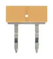


PYDN-6.2-020Y
Relay Accessory, Short Bar
- Manufacturer: OMRON INDUSTRIAL AUTOMATION
- Product type: Other Relay Accessories
- Accessory Type:Short Bar; For Use With:-; Product Range:PYF, P2RF series; SVHC:No SVHC (17-Dec-2015)
- SVHC: No SVHC (17-Dec-2015)
- For Use With: -
- Product Range: -
- Accessory Type: Short Bar
| Delivery and price | |
|---|---|
| Units per pack | 100 |
| Price | 1.02 € |
| Current stock | 10+ |
| Lead time | 30 days |
**Slim I/O Relay G2RV-SR/G3RV-SR** ## **Global standard size, low profile slim I/O relay with width 6.2 mm, slim I/O solid state relay** - Realized about 25% lower profile than conventional products, contributing to further miniaturization of the control panel. - Push-In Plus technology are used to save wiring work in comparison with conventional screw terminals. (Wiring time is reduced by 60%* in comparison with traditional screw terminals.) - No screw loosening means maintenance-free application, realizing high reliability For the recent information on models that have been certified for safety standards, refer to your OMRON website. - ‘Hand-free’ structure that holds an inserted flat-blade screwdriver to achieve easier wiring work for stranded wires. - Screw terminal is also stocked to meet the screw type needs. - Mounted relay or solid-state relay has a plug-in terminal that is difficult to bend at the time of exchange. - According to OMRON actual measurement data from November 2015. Refer to _Safety Precautions_ on page 20. ## **Slim I/O Relay Types** **G2RV-SR series mounted relay: electromagnetic relay ......from page 2 G3RV-SR series mounted relay: solid state relay ................from page 10** ## **Common matter** **Common precautions ................................................................from page 20 Common accessories (order separately).................................from page 24** **1** ## **Slim I/O Relay - G2RV SR** ## **Global standard size, low profile slim I/O relay with width 6.2 mm** - Realized about 25% lower profile than conventional products, contributing to further miniaturization of the control panel. - Realized opening and closing ability with one pole 6 A slim shape. - Micro load products for one pole 50 mA using Au-plated contacts for small load switching also available. - Since G2RV is a transparent case, confirming the state of the contact with the naked eye is possible, and easy to confirm abnormality on-site (installed location). - Screw terminal is also stocked to meet the screw type needs. For the recent information on models that have been certified for safety standards, refer to your OMRON website. - Mounted relay uses plug-in terminals that are difficult to bend when exchanging. Refer to _Safety Precautions_ on page 20. ## **Features** ## **Standard model/Micro load** Terminal x 5 - Push-in plus - Screw Operation display LED (Socket section) Release lever Mechanical indicator - Operation verification which is linked to the contact **With latching lever (Test switch)** Protective cover (Released state) Latching lever (Test switch) Protective cover (Locked condition) Latching lever (Test switch) - Circuit check operation Confirmation, reducing the inspection effort **PAT** _ ## **Push-in plus technology** Short bar insertion holes Release hole Terminal (insertion) hole "Foreign matter intrusion prevention structure" "Malfunction prevention stopper" ## **Transparent case** Relay contact Easy confirmation of the situation ## **Release lever** Relay easily fixed/removed **80 mm** **90 mm** **Plug-in terminal** Peace of mind as the terminal does not bend when replacing **2** **G2RV-SR** ## **Model Number Structure** ## **Model Number Legend** ## **G2RV-SR** @@ @ **-** @ @ (1) (2) (3) (4) (5) (6) **(1) Basic model name** G2RV: Slim I/O Relay **(3) Terminal (wire connection)** 50: Push-in plus technology 70: Screw technology **(5) Contact structure** Blank: Standard AP: Microloads **(2) Sub type** SR: Slim relay + integrated low profile socket **(4) Latching lever (test switch)** 0: Without latching lever 1: With latching lever **(6) Rated input voltage** 12, 24 VDC 24, 48 VAC/VC 100, 110, 200, 230 VAC ## **Ordering Information** |**Terminal**<br>**(Wire connection)**|**Classification**|**Latching lever**<br>**(Test switch)**|**Rated input voltage (V)**|**Rated input voltage (V)**|**Model**| |---|---|---|---|---|---| |Push-in plus<br>technology|Standard|No|DC|12|**G2RV-SR500 DC12**| |||||24|**G2RV-SR500 DC24**| ||||AC/DC|24|**G2RV-SR500 AC/DC24**| |||||48|**G2RV-SR500 AC/DC48**| ||||AC|100|**G2RV-SR500 AC100**| |||||110|**G2RV-SR500 AC110**| |||||200|**G2RV-SR500 AC200**| |||||230|**G2RV-SR500 AC230**| |||Yes|DC|24|**G2RV-SR501 DC24**| ||||AC/DC|24|**G2RV-SR501 AC/DC24**| ||Microloads|No|DC|12|**G2RV-SR500-AP DC12**| |||||24|**G2RV-SR500-AP DC24**| ||||AC/DC|24|**G2RV-SR500-AP AC/DC24**| |||||48|**G2RV-SR500-AP AC/DC48**| ||||AC|100|**G2RV-SR500-AP AC100**| |||||110|**G2RV-SR500-AP AC110**| |||||200|**G2RV-SR500-AP AC200**| |||||230|**G2RV-SR500-AP AC230**| |Screw technology|Standard|No|DC|12|**G2RV-SR700 DC12**| |||||24|**G2RV-SR700 DC24**| ||||AC/DC|24|**G2RV-SR700 AC/DC24**| |||||48|**G2RV-SR700 AC/DC48**| ||||AC|100|**G2RV-SR700 AC100**| |||||110|**G2RV-SR700 AC110**| |||||200|**G2RV-SR700 AC200**| |||||230|**G2RV-SR700 AC230**| |||Yes|DC|24|**G2RV-SR701 DC24**| ||||AC/DC|24|**G2RV-SR701 AC/DC24**| ||Microloads|No|DC|12|**G2RV-SR700-AP DC12**| |||||24|**G2RV-SR700-AP DC24**| ||||AC/DC|24|**G2RV-SR700-AP AC/DC24**| |||||48|**G2RV-SR700-AP AC/DC48**| ||||AC|100|**G2RV-SR700-AP AC100**| |||||110|**G2RV-SR700-AP AC110**| |||||200|**G2RV-SR700-AP AC200**| |||||230|**G2RV-SR700-AP AC230**| **Note:** Solid wire cannnot be used for Push-in plus technology, make sure to use stranded wire or stranded wire with ferrules. **3** **G2RV-SR** **Relay for Maintenance Model Number Legend G2RV-1 - S** @ **-** @ **- G** @ (1) (2) (3) (4) (5) (6) **(1) No. of poles** 1: 1 pole **(2) Terminal** S: plug-in **(3) Latching lever (Test switch)** ~~i~~ Blank: Without latching lever I: With latching lever **(4) Contact material** Blank: Ag alloy AP: Ag alloy + Au plating **(5) Types of relay for exchange** G: G2RV-SR series equipped Relay **(6) Rated coil voltage** Number: 11, 21, 48 VDC ## **G2RV-1-SI-G** ss ## **G2RV-1-S(-AP)-G** ## **List of Models** **Latching Rated coil Type Lever Model Applicable model voltage (V) (Test switch)** 11 **G2RV-1-S-G DC11** G2RV-SR700/500 DC12V ~~[ff~~ G2RV-SR700/500 DC24V 21 **G2RV-1-S-G DC21** G2RV-SR700/500 AC/DC24V G2RV-SR700/500 AC/DC48V No DC G2RV-SR700/500 AC100V Standard 48 **G2RV-1-S-G DC48** G2RV-SR700/500 AC110V G2RV-SR700/500 AC200V G2RV-SR700/500 AC230V G2RV-SR701/501 DC24V Yes DC 21 **G2RV-1-SI-G DC21** G2RV-SR701/501 AC/DC24V 11 **G2RV-1-S-AP-G DC11** G2RV-SR700/500-AP DC12V ~~Hii~~ G2RV-SR700/500-AP DC24V 21 **G2RV-1-S-AP-G DC21** G2RV-SR700/500-AP AC/DC24V G2RV-SR700/500-AP AC/DC48V Microload No DC G2RV-SR700/500-AP AC100V 48 **G2RV-1-S-AP-G DC48** G2RV-SR700/500-AP AC110V G2RV-SR700/500-AP AC200V G2RV-SR700/500-AP AC230V ~~(iE~~ **4** **G2RV-SR** ## **Specifications** ## **Ratings** ## **Coil ratings** |**Rated input**<br>**voltage**|**Rated current**|**Rated current**|**Rated current**|**Must operate**<br>**voltage**|**Must release**<br>**voltage**|**Power consumption**|**Power consumption**|**Maximum**<br>**allowable voltage**| |---|---|---|---|---|---|---|---|---| ||**AC**||**DC**|**Percentage of the rated voltage**||**AC (VA)**|**DC (mW)**|**Percentage of the**<br>**rated voltage**| ||**50 Hz**|**60 Hz**||||||| |12 VDC|–|–|27.9 mA|80% max.*|10% min.|–|Approx. 300 mW|110%| |24 VDC|–|–|13.5 mA|||–|Approx. 300 mW|| |24 VAC/VDC|12.5 mA|12.6 mA|12.6 mA|||Approx. 0.5 VA|Approx. 300 mW|| |48 VAC/VDC|5.9 mA|6.1 mA|5.2 mA|||Approx. 0.4 VA|Approx. 250 mW|| |100 VAC|5.9 mA|6.0 mA|–|||Approx. 0.8 VA|–|| |110 VAC|5.9 mA|5.9 mA|–|||Approx. 0.8 VA|–|| |200 VAC|3.6 mA|4.3 mA|–|||Approx. 1.7 VA|–|| |230 VAC|3.8 mA|4.5 mA|–|||Approx. 1.7 VA|–|| **Note:** The operating characteristics are measured at ambient temperature of 23°C. * Operating voltage will be, for mounting in the upside down direction, 85% max. ## **Contact ratings** |**Item**|**Standard (G2RV-SR700, 500, 701, 501)**|**Standard (G2RV-SR700, 500, 701, 501)**|**For microloads (G2RV-SR700-AP, 500-AP) *2**| |---|---|---|---| |**Contact configuration**|SPDT||| |**Load**|Resistive load<br>(cos=1)|Inductive load<br>(cos=0.4, L/R=7ms)|Resistive load<br>(cos=1)| |**Rated load**|6 A at 250 VAC<br>6 A at 30 VDC|2.5 A at 250 VAC<br>2 A at 30 VDC|50 mA at 30 VAC<br>50 mA at 36 VDC| |**Rated carry current**|6 A||50 mA| |**Maximum switching voltage**|440 VAC, 125 VDC||30 VAC, 36 VDC| |**Maximum switching current**|6 A||50 mA| |**Maximum switching power**|1,500 VA<br>180 W|500 VA<br>60 W|–| |**Failure rate P value**<br>**(reference value) *1**|10 mA at 5 VDC||1 mA at 100 mVDC| - *1. P level: 60=0.1×10[-6] /times This value is the value in switching frequency 120 operations/min. - *2. If the Au plating layer is destroyed, the number will be the same as the standard type. ## **Characteristics** |**Item**|**Item**|**Standard (G2RV-SR700, 500, 701, 501)**|**For microloads (G2RV-SR700-AP, 500-AP)**| |---|---|---|---| |**Contact resistance ***||100 mmax.|| |**Operate (Set) time ***||20 ms max.|| |**Release time ***||AC, AC/DC: 40 ms max.<br>DC: 20 ms max.|| |**Maximum operating frequency**||Mechanical: 18,000 operations/h<br>Electrical: 1,800 operations/h (rated load)|| |**Insulation resistance**||1,000 Mmin. (at 500 VDC)|| |**Dielectric strength**||Between coil and contacts: 4,000VAC 50/60 Hz 1 min<br>Contact between the same polarity: 1,000 VAC 50/60 Hz 1 min|| |**Vibration resistance**||Destruction: 10 to 55 to 10 Hz, single amplitude 0.50 mm (double amplitude 1.0 mm)<br>Malfunction: 10 to 55 to 10 Hz, single amplitude 0.50 mm (double amplitude 1.0 mm)|| |**Shock resistance**||Destruction: 1,000 m/s2<br>Malfunction: Energized 200m/s2, Non-energized 100m/s2|| |**Endurance ***|**Mechanical**|5,000,000 operations min.|| ||**Electrical**|NO contact: 70,000 operations min.<br>NC contact: 50,000 operations min.|5,000,000 operations min.| |**Ambient operating**|**temperature**|Operating: –40 to +55°C (with no icing or condensation)|| |**Ambient operating**|**humidity**|Operating: 5 to 85% RH|| |**Weight**||Approx. 30 g|| |**Contact material**||Ag alloy|Ag alloy + Au plating| **Note:** Above values are initial values. * Value is at ambient temperature of 23°C. **5** **G2RV-SR** ## **Approved standards** ## **UL508 (file No.E41643)** |**Model**|**No. of poles**|**Operation coil ratings**|**Contact ratings**|**Operations**| |---|---|---|---|---| |G2RV-SR series<br>|SPDT|12 to 48 VDC<br>24 to 230 VAC|6 A at 250 VAC (Resistive load)<br>6 A at 30 VDC (Resistive load)<br>2 A at 400 VAC (Resistive<br>load)*|6,000| - If the load voltage exceeds 250 VAC, please attach with a spacing of 12 mm min., or use a separate plate (XW5Z-EP12). 12 mm 12 mm 12 mm **==> picture [108 x 79] intentionally omitted <==** ## **TÜV (EN 61810-1)** |**Model**|**No. of poles**|**Operation coil ratings**|**Contact ratings**|**Operations**| |---|---|---|---|---| |G2RV-SR series<br>|SPDT|12, 24 VDC<br>24, 48 VAC/VDC<br>100, 110, 200, 230 VAC|6 A at 250 VAC (Resistive load)<br>6 A at 30 VDC (Resistive load)<br>2 A at 400 VAC (Resistive<br>load)*|50,000<br>50,000<br>6,000| * If the load voltage exceeds 250 VAC, please attach with a spacing of 12 mm min., or use a separate plate (XW5Z-EP12). 12 mm 12 mm 12 mm **==> picture [108 x 78] intentionally omitted <==** ## **Engineering Data** ## **Endurance curve (N.O. side)** **==> picture [158 x 155] intentionally omitted <==** **----- Start of picture text -----**<br> 1000<br>30 VDC resistive load<br>250 VAC resistive load<br>100<br>30 VDC<br>resistive load<br>250 VAC resistive load<br>10<br>0 2 4 6<br>Opening and closing current (A)<br>3 operations)Number of operations (x 10<br>**----- End of picture text -----**<br> ## **Switching capacity of DC resistive load** **==> picture [158 x 156] intentionally omitted <==** **----- Start of picture text -----**<br> 10.0<br>1.0<br>0.1<br>20 60 100 140 180 220<br>DC switching voltage (V)<br>DC breaking current (A)<br>**----- End of picture text -----**<br> **6** **G2RV-SR** **Dimensions** **(unit: mm)** ## **Slim I/O Relay + socket** ## **Push-in plus technology** **Models without latching lever (without test switch) G2RV-SR500 G2RV-SR500-AP** **==> picture [380 x 326] intentionally omitted <==** **----- Start of picture text -----**<br> Terminal Arrangement/Internal Connection Diagram<br>(TOP VIEW)<br>78 max. 12 VDC<br>Input circuit<br>A1<br>A2<br>G2RV<br>3.4<br>74.5<br>65.89 Other voltage<br>35.25 Input circuit<br>(5.05) 18.78<br>A1<br>A2<br>12 G2RV<br>14<br>11<br>78.77<br>35.3 90 max. 24 VDC<br>Input circuit<br>12<br>A1<br>14<br>A2<br>G2RV 11<br>* : Diode bridge<br>(5.05)<br>18.78 : Light emitting diode<br>6.2 max.<br>35.25<br>51.72<br>59.71 12<br>14<br>11<br>**----- End of picture text -----**<br> **Models with latching lever (with test switch) G2RV-SR501** **==> picture [384 x 322] intentionally omitted <==** **----- Start of picture text -----**<br> Terminal Arrangement/Internal Connection Diagram<br>(TOP VIEW)<br>81 max. 12 VDC<br>Input circuit<br>A1<br>A2<br>G2RV<br>3.4<br>77.5<br>65.89 Other voltage<br>35.25 Input circuit<br>(5.05) 18.78<br>A1<br>A2<br>12 G2RV<br>14<br>11<br>78.77<br>35.3 90 max. 24 VDC<br>Input circuit<br>A1 12<br>14<br>A2<br>G2RV<br>11<br>* : Diode bridge<br>(5.05)<br>18.78 : Light emitting diode<br>6.2 max.<br>35.25<br>51.72<br>59.71 12<br>14<br>11<br>**----- End of picture text -----**<br> **7** **G2RV-SR** ## **Screw terminal** **Models without latching lever (without test switch) G2RV-SR700 G2RV-SR700-AP** **==> picture [386 x 331] intentionally omitted <==** **----- Start of picture text -----**<br> Terminal Arrangement/Internal Connection Diagram<br>(TOP VIEW)<br>12 VDC<br>Input circuit<br>78 max.<br>A1<br>A2<br>G2RV<br>3.4<br>74.5<br>65.89 Other voltage<br>35.18 Input circuit<br>(5.05) 18.71<br>A1<br>A2<br>12 G2RV<br>14<br>11<br>78.77<br>35.3 90 max. 24 VDC<br>Input circuit<br>12<br>A1<br>14<br>A2<br>G2RV 11<br>* : Diode bridge<br>(5.05)<br>18.71 : Light emitting diode<br>35.18 6.2 max.<br>51.65<br>56.2<br>12<br>14<br>11<br>**----- End of picture text -----**<br> **Models with latching lever (with test switch) G2RV-SR701** **==> picture [173 x 16] intentionally omitted <==** **----- Start of picture text -----**<br> Terminal Arrangement/Internal Connection Diagram<br>(TOP VIEW)<br>**----- End of picture text -----**<br> **==> picture [25 x 6] intentionally omitted <==** **----- Start of picture text -----**<br> 12 VDC<br>**----- End of picture text -----**<br> **==> picture [384 x 297] intentionally omitted <==** **----- Start of picture text -----**<br> Input circuit<br>81 max.<br>A1<br>A2<br>G2RV<br>3.4<br>77.5<br>65.89 Other voltage<br>35.18 Input circuit<br>(5.05) 18.71<br>A1<br>A2<br>G2RV<br>12<br>14<br>11<br>78.77<br>35.3 90 max. 24 VDC<br>Input circuit<br>A1 12<br>14<br>A2<br>G2RV<br>11<br>* : Diode bridge<br>(5.05)<br>18.71 : Light emitting diode<br>35.18 6.2 max.<br>51.65<br>56.2<br>12<br>14<br>11<br>**----- End of picture text -----**<br> **8** **G2RV-SR** ## **Relay for maintenance** **Models without latching lever G2RV-1-S-G G2RV-1-S-AP-G** **==> picture [341 x 516] intentionally omitted <==** **----- Start of picture text -----**<br> 5.2 max. 30.5 max.<br>Terminal Arrangement/<br>Internal Connection Diagram<br>(TOP VIEW)<br>33 max. (Input circuit)<br>16.2 14 — 11 12 A1 A2<br>. i<br>Po<br>1.8 0.5 PTT v 2.4 a<br>3.5<br>5.04 5.04<br>3<br>Ee 22<br>5.2 max.<br>30.5 max.<br>Terminal Arrangement/<br>Internal Connection Diagram<br>(TOP VIEW)<br>a<br>(Input circuit)<br>36 max.<br>14 11 12 A1 A2<br>16.2<br>2 |<br>1.8 0.5 PTT<br>2.4<br>3.5<br>[Pesala EEL si<br>5.04<br>eat 5.04 22 3<br>**----- End of picture text -----**<br> **Models with latching lever (test switch) G2RV-1-SI-G** **9** ## **Slim I/O Solid State Relay - G3RV SR** ## **Global standard size, low profile type slim I/O solid state relay with width 6.2 mm.** - Realized about 25% lower profile than conventional products, contributing to further miniaturization of the control panel. - Optimal slim, high frequency, high-speed opening and closing SSR (solid state relay). SSR (solid state relay). 3 A (DC), and 2 A (AC). load, opening and closing load of 100 LED. are difficult to bend when exchanging. Refer to _Safety Precautions_ on page 20. ~~zz~~ • Realized a slim shape with a switching capacity up to 3 A (DC), and 2 A (AC). • Because MOSFET is used for the outlet element for the DC load, opening and closing load of 100 A to 3 A is possible. • Check operating status at a glance at the operating display LED. • Mounted I/O SSR (solid-state relay) uses plug-in terminals that are difficult to bend when exchanging. Refer to _Safety Precautions_ on page 20. ~~zz~~ **Features Push-in plus technology** Terminal x 5 • Push-in Short bar insertion holes • Screw Release hole Release lever ~~=~~ Operation display LED (Socket section) Operation display LED (SSR section) Terminal (insertion) hole ~~:~~ **Release lever** ~~|~~ Relay easily fixed/removed ~~fa~~ d **90 mm Plug-in terminal** Peace of mind as the terminal does not bend when replacing **80 mm** For the recent information on models that have been certified for safety standards, refer to your OMRON website. **10** **G3RV-SR** ## **Model Number Structure** ## **Model Number Legend** ## **G3RV-SR** @ @ @ **-** @ @ (1) (2) (3) (4) (5) ## **(1) Basic model name** G3RV: Slim I/O Solid State Relay ## **(2) Sub type** ## **(4) Output voltage specification** A : AC output (triac) zero cross function available AL : AC output (triac) zero cross function not available D : DC output (MOS FET) SR: Slim solid relay + integrated low profile socket ## **(5) Rated voltage input** ## **(3) Terminal (wire connection)** 500: Push-in plus technology 700: Screw technology 12, 24 VDC 24, 48 VAC/VDC 100, 110, 200, 230 VAC **11** **G3RV-SR** ## **Ordering Information** |**Terminal**<br>**(wire connection)**|**Applicable**<br>**output load**|**Zero cross**<br>**function**|**Rated input voltage**<br>**(V)**|**Rated input voltage**<br>**(V)**|**Model**| |---|---|---|---|---|---| |Push-in plus<br>technology|DC load|—|DC|12|**G3RV-SR500-D DC12**| |||||24|**G3RV-SR500-D DC24**| ||||AC/DC|24|**G3RV-SR500-D AC/DC24**| |||||48|**G3RV-SR500-D AC/DC48**| ||||AC|100|**G3RV-SR500-D AC100**| |||||110|**G3RV-SR500-D AC110**| |||||200|**G3RV-SR500-D AC200**| |||||230|**G3RV-SR500-D AC230**| ||AC load|Yes|DC|12|**G3RV-SR500-A DC12**| |||||24|**G3RV-SR500-A DC24**| ||||AC/DC|24|**G3RV-SR500-A AC/DC24**| |||||48|**G3RV-SR500-A AC/DC48**| ||||AC|100|**G3RV-SR500-A AC100**| |||||110|**G3RV-SR500-A AC110**| |||||200|**G3RV-SR500-A AC200**| |||||230|**G3RV-SR500-A AC230**| |||No|DC|12|**G3RV-SR500-AL DC12**| |||||24|**G3RV-SR500-AL DC24**| ||||AC/DC|24|**G3RV-SR500-AL AC/DC24**| |||||48|**G3RV-SR500-AL AC/DC48**| ||||AC|100|**G3RV-SR500-AL AC100**| |||||110|**G3RV-SR500-AL AC110**| |||||200|**G3RV-SR500-AL AC200**| |||||230|**G3RV-SR500-AL AC230**| |Screw technology|DC load|—|DC|12|**G3RV-SR700-D DC12**| |||||24|**G3RV-SR700-D DC24**| ||||AC/DC|24|**G3RV-SR700-D AC/DC24**| |||||48|**G3RV-SR700-D AC/DC48**| ||||AC|100|**G3RV-SR700-D AC100**| |||||110|**G3RV-SR700-D AC110**| |||||200|**G3RV-SR700-D AC200**| |||||230|**G3RV-SR700-D AC230**| ||AC load|Yes|DC|12|**G3RV-SR700-A DC12**| |||||24|**G3RV-SR700-A DC24**| ||||AC/DC|24|**G3RV-SR700-A AC/DC24**| |||||48|**G3RV-SR700-A AC/DC48**| ||||AC|100|**G3RV-SR700-A AC100**| |||||110|**G3RV-SR700-A AC110**| |||||200|**G3RV-SR700-A AC200**| |||||230|**G3RV-SR700-A AC230**| |||No|DC|12|**G3RV-SR700-AL DC12**| |||||24|**G3RV-SR700-AL DC24**| ||||AC/DC|24|**G3RV-SR700-AL AC/DC24**| |||||48|**G3RV-SR700-AL AC/DC48**| ||||AC|100|**G3RV-SR700-AL AC100**| |||||110|**G3RV-SR700-AL AC110**| |||||200|**G3RV-SR700-AL AC200**| |||||230|**G3RV-SR700-AL AC230**| **Note:** Solid wire cannnot be used for Push-In Plus terminal type, make sure to use stranded wire or stranded wire with ferrules. **12** **G3RV-SR** ## **Solid state relay for maintenance** ## **Model Number Legend** ## **G3RV-** @ @ **S** @ @ (1) (2) (3) (4) (5) ## **(1) Output voltage (3) Terminal specification** S: Plug-in type S: Plug-in type D: DC output 2: AC output **(4) Zero cross functions** Blank: Zero cross function available ## **(2) Rated current** L: Zero cross function not available 02: AC output 2 A 03: DC output 3 A **(5) Rated input voltage** Number: 12, 24, 48 VDC ## **List of Models** |**Insulation**<br>**method**|**Operation**<br>**Display**|**Output**<br>**(SSR)**|**Zero cross**<br>**Function**|**Rated**<br>**output**<br>**Load ***|**Rated input**<br>**voltage**<br>**(socket)**|**Model**|**Applicable model**| |---|---|---|---|---|---|---|---| |Photo-<br>triac|Yes<br>(green)|AC|Yes|2 A<br>(at 100 to<br>240<br>VAC)<br>~~ee~~<br>~~—~~<br>~~||||~~<br>~~||ee~~<br>~~a~~<br>~~||||~~<br>~~||ee~~|12 VDC<br>~~ee~~|**G3RV-202S DC12**<br>~~ee~~|G3RV-SR700/500-A DC12V| ||||||24 VDC<br>~~ee~~<br>~~—~~<br>~~|~~|**G3RV-202S DC24**<br>~~ee~~<br>~~—~~|G3RV-SR700/500-A DC24V| ||||||24 VAC/VDC<br>~~—~~<br>~~||~~||G3RV-SR700/500-A AC/DC24V| ||||||48 VAC/VDC<br>~~—~~<br>~~|||~~|**G3RV-202S DC48**<br>~~—~~<br>~~ee~~|G3RV-SR700/500-A AC/DC48V| ||||||100 VAC<br>~~||~~||G3RV-SR700/500-A AC100V| ||||||110 VAC<br>~~||~~<br>~~||~~||G3RV-SR700/500-A AC110V| ||||||200 VAC<br>~~|~~<br>~~||~~||G3RV-SR700/500-A AC200V| ||||||230 VAC<br>~~||ee~~||G3RV-SR700/500-A AC230V<br>~~e~~| ||||No||12 VDC<br>~~||ee~~|**G3RV-202SL DC12**<br>~~ee~~|G3RV-SR700/500-AL DC12V<br>~~e~~| ||||||24 VDC<br>~~ee~~<br>~~a~~<br>~~||~~|**G3RV-202SL DC24**<br>~~ee~~<br>~~a~~|G3RV-SR700/500-AL DC24V<br>~~e~~| ||||||24 VAC/VDC<br>~~a~~<br>~~||~~||G3RV-SR700/500-AL AC/DC24V| ||||||48 VAC/VDC<br>~~a~~<br>~~|||~~|**G3RV-202SL DC48**<br>~~a~~<br>~~ee~~|G3RV-SR700/500-AL AC/DC48V| ||||||100 VAC<br>~~|||~~||G3RV-SR700/500-AL AC100V| ||||||110 VAC<br>~~||~~<br>~~||~~||G3RV-SR700/500-AL AC110V| ||||||200 VAC<br>~~|~~<br>~~||~~||G3RV-SR700/500-AL AC200V| ||||||230 VAC<br>~~||ee~~||G3RV-SR700/500-AL AC230V<br>~~e~~| |Photo-<br>voltage<br>coupler||DC|–|3 A<br>(at 5 to<br>24 VDC)<br>~~||ee~~<br>~~a~~<br>~~||||~~<br>~~||~~|12 VDC<br>~~||ee~~|**G3RV-D03SL DC12**<br>~~ee~~|G3RV-SR700/500-D DC12V<br>~~e~~| ||||||24 VDC<br>~~ee~~<br>~~a~~<br>~~||~~|**G3RV-D03SL DC24**<br>~~ee~~<br>~~a~~|G3RV-SR700/500-D DC24V<br>~~e~~| ||||||24 VAC/VDC<br>~~a~~<br>~~||~~||G3RV-SR700/500-D AC/DC24V| ||||||48 VAC/VDC<br>~~a~~<br>~~|||~~|**G3RV-D03SL DC48**<br>~~a~~|G3RV-SR700/500-D AC/DC48V| ||||||100 VAC<br>~~|||~~||G3RV-SR700/500-D AC100V| ||||||110 VAC<br>~~||~~<br>~~|~~||G3RV-SR700/500-D AC110V| ||||||200 VAC<br>~~||~~||G3RV-SR700/500-D AC200V| ||||||230 VAC<br>~~||~~||G3RV-SR700/500-D AC230V| * Different depending on the ambient temperature. For more details, refer to _Load current vs. ambient rated temperature_ on page 16. **13** **G3RV-SR Specifications** ## **Rating (ambient temperature 25°C)** ## **Input** ## **G3RV-SR700/500-A series** |**Rated input**<br>**voltage**|**Rated current**|**Rated current**|**Rated current**|**Must operate**<br>**voltage**|**Must release**<br>**voltage**|**Input voltage**| |---|---|---|---|---|---|---| ||**AC**||**DC**|||**Percentage of the**<br>**rated voltage**| ||**50 Hz**|**60 Hz**||||| |12 VDC|–|–|15.0 mA|10.8 V max.|1 V min.|±10%| |24 VDC|–|–|12.0 mA|21.6 V max.||| |24 VAC/VDC|11.3 mA|11.4 mA|11.0 mA|21.6 V max.||| |48 VAC/VDC|6.8 mA|6.9 mA|6.0 mA|43.2 V max.||| |100 VAC|6.2 mA|6.2 mA|–|90 V max.||| |110 VAC|6.2 mA|6.2 mA|–|99 V max.||| |200 VAC|3.7 mA|4.4 mA|–|180 V max.||| |230 VAC|3.8 mA|4.6 mA|–|207 V max.||| |**G3RV-SR700/500-AL series**||||||| |**Rated input**<br>**voltage**|**Rated current**|||**Must operate**<br>**voltage**|**Must release**<br>**voltage**|**Input voltage**| ||**AC**||**DC**|||**Percentage of the**<br>**rated voltage**| ||**50 Hz**|**60 Hz**||||| |12 VDC|–|–|15.0 mA|10.8 V max.|1 V min.|±10%| |24 VDC|–|–|12.0 mA|21.6 V max.||| |24 VAC/VDC|11.4 mA|11.5 mA|11.0 mA|21.6 V max.||| |48 VAC/VDC|7.7 mA|7.7 mA|6.9 mA|43.2 V max.||| |100 VAC|7.3 mA|7.3 mA|–|90 V max.||| |110 VAC|7.3 mA|7.3 mA|–|99 V max.||| |200 VAC|3.8 mA|4.6 mA|–|180 V max.||| |230 VAC|3.9 mA|4.7 mA|–|207 V max.||| ## **G3RV-SR700/500-D series** |**Rated input**<br>**voltage**|**Rated current**|**Rated current**|**Rated current**|**Must operate**<br>**voltage**|**Must release**<br>**voltage**|**Input voltage**| |---|---|---|---|---|---|---| ||**AC**||**DC**|||**Percentage of the**<br>**rated voltage**| ||**50 Hz**|**60 Hz**||||| |12 VDC|–|–|8.0 mA|10.8 V max.|1 V min.|±10%| |24 VDC|–|–|4.6 mA|21.6 V max.||| |24 VAC/VDC|5.0 mA|5.1 mA|4.3 mA|21.6 V max.||| |48 VAC/VDC|6.8 mA|6.9 mA|6.0 mA|43.2 V max.||| |100 VAC|6.2 mA|6.2 mA|–|90 V max.||| |110 VAC|6.2 mA|6.2 mA|–|99 V max.||| |200 VAC|3.7 mA|4.4 mA|–|180 V max.||| |230 VAC|3.9 mA|4.5 mA|–|207 V max.||| ## **Output** |**Item**|**G3RV-SR700/500-A(L)**|**G3RV-SR700/500-D**| |---|---|---| |**Rated load voltage**|100 to 240 VAC (50/60 Hz)|5 to 24 VDC| |**Load voltage range**|75 to 264 VAC (50/60 Hz)|3 to 26.4 VDC| |**Load current**|0.1 to 2 A (Ambient temperature=25°C)|100A to 3 A (Ambient temperature=25°C)| |**Inrush current resistance**|30 A (60 Hz, 1 cycle)|30 A (60 Hz, 1 cycle)| |**Permissible l2t; Joule integral value**<br>**(reference value)**|15A2s|9 A2s| |**Applied load capacity**|400 W<br>(Output voltage: 200 VAC)|72 W<br>(Output voltage: 24 VDC)| **14** **G3RV-SR** ## **Characteristics** |**Item**|**G3RV-SR700/500-A**|**G3RV-SR700/500-AL**|**G3RV-SR700/500-D**| |---|---|---|---| |**Operate time**|1/2 cycle of load power supply<br>+1 ms max.|3 ms max.|6 ms max.| |**Release time**|60 ms max.|60 ms max.|60 ms max.| |**Output ON voltage drop**|1.6 V (RMS) max.||–| |**Output ON resistance**|–||0.3max. (at 24 VDC)| |**Leaked current**|5 mA max. (at 200 VAC, 50/60 Hz)||10 µA max. (at 24 VDC)| |**Insulation resistance**|100 Mmin. (at 500 VDC)||| |**Dielectric strength**|Between input and output 2,500 VAC 50/60 Hz 1 min||| |**Vibration resistance**|Malfunction: 10 to 55 to 10 Hz double amplitude 0.70 mm||| |**Shock resistance**|300m/s2||| |**Ambient operating temperature**|Storage: –30 to +100°C (with no icing or no condensation)<br>Operating: –30 to +55°C (with no icing or no condensation)||| |**Ambient operating humidity**|45 to 85% RH||| |**Weight**|Approx. 38 g||| |**Pollution degree**|2||| |**The degree of protection by**<br>**IEC60529**|IP20||| |**Rated impulse dielectric**<br>**strength**|4.0 kV/III||| |**Load category**|LC-A||DC-12| |**Overload current profile**|1.5Ie 1.1Ue<br>5s ON, 10s OFF, 10 cycles||| |**Rated insulation voltage**|240 V||| ## **Approved standards** ## **UL 508 (file No.E64562)** |**Model**|**Input ratings**|**Contact ratings**| |---|---|---| |G3RV-SR700/500-D series|12, 24 VDC<br>24, 48 VAC/VDC<br>100, 110, 200, 230 VAC|24 VDC 3 A (resistive load) at 25°C| |G3RV-SR700/500-A(L) series|12, 24 VDC<br>24, 48 VAC/DC<br>100, 110, 200, 230 VAC|240 VAC 2 A (resistive load) at 25°C| ## **TÜV(EN 62314)** |**Model**|**Input ratings**|**Contact ratings**| |---|---|---| |G3RV-SR700/500-D series|12, 24 VDC<br>24, 48 VAC/VDC<br>100, 110, 200, 230 VAC|24 VDC 3 A (resistive load)| |G3RV-SR700/500-A(L) series|12, 24 VDC<br>24, 48 VAC/VDC<br>100, 110, 200, 230 VAC|240 VAC 2 A (resistive load)| **15** **G3RV-SR** ## **Engineering Data** ## **Load current vs. ambient rated temperature** ## **G3RV-SR700/500-A(L) series** Product mounting spacing 10 mm (Separate Mounting) Close mounting (up to 5 units *) **==> picture [413 x 153] intentionally omitted <==** **----- Start of picture text -----**<br> 5 5<br>4 4<br>3 3<br>2 2<br>1 1<br>0.2<br>0 0<br>−30 −20 0 20 25 40 55 60 80 100 −30 −20 0 20 25 40 55 60 80 100<br>Ambient temperature (°C) Ambient temperature (°C)<br>Load current (A) Load current (A)<br>**----- End of picture text -----**<br> ## **G3RV-SR700/500-D series** Product mounting spacing 10 mm (Separate Mounting) Close mounting (up to 5 units *) **==> picture [413 x 153] intentionally omitted <==** **----- Start of picture text -----**<br> 5 5<br>4 4<br>3 3<br>2 2<br>1 1<br>0.5<br>0 0<br>−30 −20 0 20 25 40 55 60 80 100 −30 −20 0 20 25 40 55 60 80 100<br>Ambient temperature (°C) Ambient temperature (°C)<br>Load current (A) Load current (A)<br>**----- End of picture text -----**<br> * When five or more are installed, install with 10 mm space between each. For details, please refer to _Mounting_ on page 23. ## **Inrush Current Resistance: Non-repetitive** Keep the inrush current to below the inrush current resistance value (i.e., below the broken line) if it occurs repetitively. ## **G3RV-SR700/500-A(L) series** **==> picture [155 x 154] intentionally omitted <==** **----- Start of picture text -----**<br> 40<br>35<br>30<br>25<br>20<br>15<br>10<br>5<br>0<br>10 30 50 100 300 500 1,000 3,000 5,000<br>Energized time (ms)<br>Inrush current (A.Peak)<br>**----- End of picture text -----**<br> ## **G3RV-SR700/500-D series** **==> picture [155 x 154] intentionally omitted <==** **----- Start of picture text -----**<br> 40<br>35<br>30<br>25<br>20<br>15<br>10<br>5<br>010 30 50 100 300 500 1,000 3,000 5,000<br>Energized time (ms)<br>Inrush current (A.Peak)<br>**----- End of picture text -----**<br> **16** **G3RV-SR** **Dimensions** **(unit: mm)** ## **Solid state relay + socket Push-in plus technology G3RV-SR500** **==> picture [205 x 270] intentionally omitted <==** **----- Start of picture text -----**<br> 78 max.<br>3.4<br>74.5<br>65.89<br>35.25<br>(5.05) 18.78<br>78.77<br>35.3 90 max.<br>(5.05)<br>18.78<br>6.2 max.<br>35.25<br>51.72<br>59.71<br>**----- End of picture text -----**<br> **==> picture [109 x 362] intentionally omitted <==** **----- Start of picture text -----**<br> Terminal Arrangement/<br>Internal Connection Diagram<br>(TOP VIEW)<br>12 VDC<br>Input circuit<br>A1<br>G3RV A2<br>A2–<br>INPUT<br>A1+<br>13 (+)<br>OUTPUT<br>14 (–)<br>The information in 12<br>parentheses in for 14<br>a DC output.<br>13<br>24 VDC<br>Input circuit<br>A1<br>G3RV A2<br>A2–<br>INPUT<br>A1+<br>13 (+)<br>OUTPUT<br>14 (–)<br>The information in 12<br>parentheses in for 14<br>a DC output.<br>13<br>**----- End of picture text -----**<br> ## **Other voltage** **==> picture [124 x 176] intentionally omitted <==** **----- Start of picture text -----**<br> Input circuit<br>A1<br>G3RV<br>A2<br>A2–<br>INPUT<br>A1+<br>13 (+)<br>OUTPUT<br>14 (–)<br>The information in 12<br>parentheses in for<br>a DC output. 14<br>13<br>* : Diode bridge<br>: Light emitting diode<br>**----- End of picture text -----**<br> **17** **G3RV-SR** ## **Screw technology G3RV-SR700** **==> picture [341 x 370] intentionally omitted <==** **----- Start of picture text -----**<br> Terminal Arrangement/<br>Internal Connection Diagram<br>(TOP VIEW)<br>78 max. 12 VDC<br>Input circuit<br>A1<br>3.4<br>74.5<br>65.89 G3RV A2<br>35.18<br>A2–<br>(5.05) 18.71<br>INPUT<br>A1+<br>13 (+)<br>OUTPUT<br>14 (–)<br>The information in 12<br>78.77 parentheses in for 14<br>35.3 90 max. a DC output.<br>13<br>24 VDC<br>Input circuit<br>A1<br>(5.05)<br>18.71 G3RV A2<br>35.18 6.2 max.<br>51.65 A2–<br>56.2 INPUT<br>A1+<br>13 (+)<br>OUTPUT<br>14 (–)<br>The information in 12<br>parentheses in for 14<br>a DC output.<br>13<br>**----- End of picture text -----**<br> ## **Other voltage** **==> picture [124 x 176] intentionally omitted <==** **----- Start of picture text -----**<br> Input circuit<br>A1<br>G3RV<br>A2<br>A2–<br>INPUT<br>A1+<br>13 (+)<br>OUTPUT<br>14 (–)<br>The information in 12<br>parentheses in for<br>a DC output. 14<br>13<br>* : Diode bridge<br>: Light emitting diode<br>**----- End of picture text -----**<br> **18** **G3RV-SR** ## **Solid state relay for maintenance** **G3RV-D03SL G3RV-202S(L)** **==> picture [271 x 202] intentionally omitted <==** **----- Start of picture text -----**<br> Terminal Arrangement/<br>Internal Connection Diagram<br>(TOP VIEW)<br>G3RV-D03SL (input circuit)<br>30.5 max. Input<br>Load<br>33 max.<br>15.8<br>14 13 A1 A2<br>1.8 3.5<br>2.4 G3RV-202S(L) (input circuit)<br>22<br>5.04 3 Input<br>5.2 max.<br>Load<br>ak<br>14 13 A1 A2<br>**----- End of picture text -----**<br> **19** **G2RV-SR/G3RV-SR Safety Precautions** **Be sure to read the** _**Safety Precautions for All Relays**_ **in the website at the following URL: http://www.ia.omron.com/.** ## **Format of Warning Indications** **Indicates a potentially hazardous situation which, if not avoided, will result in minor or WARNING moderate injury, or may result in serious injury or death. Additionally, there may be significant property damage.** **Indicates a potentially hazardous situation CAUTION which, if not avoided, may result in minor or moderate injury or in property damage. Precautions Indicates supplementary comments on what to do or avoid doing, to use the for Safe Use product safety. Precautions Includes operating precautions to ensure for Correct that the product will operate properly and that performance and functions will not be Use adversely affected.** ## **Meaning of Graphic Symbols for Ensuring Product Safety** **==> picture [34 x 150] intentionally omitted <==** **Indicates the possibility of electric shock under specific conditions.** **Used for general CAUTION, WARNING, or DANGER precautions for which there is no specified symbol. (This symbol is also used as the alerting symbol, but shall not be used in this meaning on the product.)** **Indicates the possibility of explosion or rupture under specific conditions.** **Indicates the possibility of injuries by high temperature under specific conditions.** ## **WARNING** **Ensure that the socket is not charged during wiring and maintenance. Not doing so may result in electric shock.** **Do not touch the terminal section of the G2RV-SR or the surrounding area while the power is being supplied. Doing so may result in electric shock.** **Minor burns may occasionally occur. Do not touch the G3RV or the heat sink while the power is being supplied or immediately after the power supply has been turned OFF. The G3RV becomes extremely hot.** **Provide a space of at least 3 mm between the G2RVSR and ground. Not doing so may result in a ground fault.** ## **Precautions for Safe Use** ## **Transport** - Do not use the product if it has been dropped on the ground. Dropping the product may adversely affect performance. - Do not drop the product or subject it to abnormal vibration or shock during transportation or mounting. Doing so may result in deterioration of performance, malfunction, or failure. - Do not transport the product without it being packaged. Doing so may result in damage, malfunction, or failure. - Do not transport the G3RV under the following conditions. Doing so may result in damage, malfunction, or deterioration of performance characteristics. - High temperature, high humidity conditions - Conditions such as temperature change that causes rapid condensation - Condition where it is not packaged ## **Operating and Storage Environments** - Do not use or store the product in the following locations. Doing so may result in damage, malfunction, or deterioration of performance characteristics. - Do not store in locations subject to ambient storage temperatures outside the range –40 to 70°C (for G2RV) and outside the range –30 to 100°C (for G3RV). - Locations subject to relative humidity outside the range 5% to 85% (for G2RV) and outside the range 45% to 85% (for G3RV). - Locations subject to high temperature or high humidity. - Conditions such as temperature change that causes rapid condensation ## **CAUTION** **Minor electrical shock may occasionally occur. Do not touch the G3RV terminal section (i.e., current carrying parts) while the power is being supplied.** - Locations where corrosive gases or flammable gases are present - Location where rainwater or water droplets gets splashed - Location with splashes of water, oil, and chemicals, etc. - Locations with much dust, salt, and iron powder - Location with blockers **The G3RV may rupture if short-circuit current flows. As protection against accidents due to short-circuiting, be sure to install protective devices, such as fuses and no-fuse breakers, on the power supply side.** **Minor electrical shock may occasionally occur. Do not touch the main circuit terminals on the G3RV immediately after the power supply has been turned OFF.** **Shock may result due to the electrical charge stored in the built-in snubber circuit. Note: G3RV-202S(L), G3RV-SR500/700-A(L) series models only** - Where static electricity or noise occurs - Where strong electromagnetic field is generated - Where there is a risk of exposure to radioactivity - Do not use or store Sockets in environments that contain silicone gas, sulfidizing gas (e.g., SO2 or H2S), or organic gas, or near materials that contain silicone. Doing so may cause the contacts to be unstable or to fail. ## **Handling <G3RV>** - Keep the G3RV well ventilated. - There is a risk of short-circuiting or burning due to G3RV overheating. **20** **G2RV-SR/G3RV-SR** ## **Mounting** - Before you start wiring, please make sure that the socket is securely attached to the mounting rail. If the socket is unstable, it may come loose and risk of injury towards the workers. - Please insert the flat-blade screwdriver to the bottom of the hole. If you do not insert the flat-blade screwdriver correctly, the cable will not be connected correctly. - When lubricant such as oil is attached to the tip of the driver, the driver will fall off, with a risk of injury towards the workers. ## **Usage** - Please select the load within the rated range. Doing so may result in damage, malfunction, or failure. - Please use the power of the rated frequency. It may cause malfunction, failure, or risk of burnout. ## **<G3RV>** - Install G3RV according to instructions _Mounting_ on page 23. If you install in the wrong direction, abnormal heat is generated, and may lead to short-circuiting or burning the output element. - G3RV is an SSR that generates heat. Please observe the ambient temperature setting range of G3RV. If installing in an enclosed space, set a fan, and ventilate. - When mounting G3RV to DIN rail, firmly fits into the groove. If it is not properly installed, there is a risk of it falling. ## **Wiring** - For the current to be applied, make sure a wire size with margin is used. Otherwise, excessive heat generated by the wires may cause burning. - Do not attempt to use the wire if the coat is torn. Not doing so may result in electric shock. - Always turn OFF the power supply before performing wiring. Not doing so may cause electrical shock. ## **<G3RV>** - The wires of the socket for G3RV socket should not be passed through the same duct as that being connected to the high-voltage power supply. Otherwise, inductive noise may damage the G3RV or cause it to malfunction. ## **Push-in plus technology** - Do not wire anything to the release holes. - Do not tilt or twist a flat-blade screwdriver while it is inserted into a release hole on the terminal. The terminal may be damaged. - Insert a flat-blade screwdriver into the release holes at an angle. The terminal may be damaged if you insert the screwdriver straight in. - Do not allow the flat-blade screwdriver to fall out while it is inserted into a release hole. - Do not bend the wire past its natural bending radius or pull on it with excessive force. Doing so may cause the wire disconnection. - Do not insert more than one wire into each terminal (insertion) hole. - To prevent wiring materials from smoking or ignition, use the wiring materials given in the following table. |**Recommended Wire**<br> 2|**Stripping length**|**Stripping length**| |---|---|---| ||**Ferrules**<br>**When using**<br>**terminal**<br>|**Ferrules**<br>**When not using**<br>**terminal**<br>| ## **Precautions for Correct Use** - Do not use or store the product in the following locations. Doing so may result in damage, malfunction, or deterioration of performance characteristics. - Where vibration or shock is directly transmitted to the body - Do not use the product where the socket could touch a solvent or alkaline agent. - Do not insert short bar in the hole for wire or screw driver, it may cause the result of failure of pull out. If insert short bar in the hole for wire or screw driver and try to pull out, it may cause damage for short bar or socket. ## **Push-in plus technology** ## **1. Connecting Wires to the Push-in plus technology Part Names of the Terminal** **==> picture [96 x 63] intentionally omitted <==** **==> picture [63 x 15] intentionally omitted <==** **----- Start of picture text -----**<br> Release hole<br>Terminal (Insertion) hole<br>**----- End of picture text -----**<br> ## **Connecting Wires with Ferrules** Insert the ferrule straight into the terminal until the end strikes the terminal. **==> picture [138 x 63] intentionally omitted <==** **----- Start of picture text -----**<br> Release hole<br>Terminal<br>(Insertion) hole<br>Ferrules<br>**----- End of picture text -----**<br> ## **Connecting Stranded Wires** Use the following procedure to connect the wires to the terminal. - (1) Hold a flat-blade screwdriver at an angle and insert it into the release hole. - The angle should be between 10°and15°. If the flat-blade screwdriver is inserted correctly, you will feel the spring in the release hole respond. - (2) With the flat-blade screwdriver still inserted into the release hole, insert the wire into the terminal hole until it strikes the terminal. - (3) Remove the flat-blade screwdriver from the release hole. **==> picture [223 x 64] intentionally omitted <==** **----- Start of picture text -----**<br> Flat-blade screwdriver<br>(1) (3)<br>10 to 15° (3)<br>(1)<br>(2) Stranded Wires<br>(2)<br>**----- End of picture text -----**<br> ## **Checking Connections** - After insertion, pull gently on the wire to make sure that it will not come out (i.e., to confirm that it is held by the terminal). - To prevent short circuits, insert the stripped part of a stranded or the conductive part of a ferrule until it is hidden inside the terminal insertion hole. (See following diagram.) **Note:** Use Ferrules with UL certification (R/C). ## **Disposal** - When disposing of the product, do not put into the fire. **21** **G2RV-SR/G3RV-SR** ## **2. Removing Wires from the Terminal** Use the following procedure to remove wires from the terminal. The same method is used to remove stranded wires and ferrules. - (1) Hold a flat-blade screwdriver at an angle and insert it into the release hole. - (2) With the flat-blade screwdriver still inserted into the release hole, remove the wire from the terminal insertion hole. - (3) Remove the flat-blade screwdriver from the release hole. **==> picture [172 x 70] intentionally omitted <==** **----- Start of picture text -----**<br> Flat-blade screwdriver<br>(1) (3)<br>10 to 15° (3)<br>(1)<br>(2)<br>Wire<br>> c—\<br>(2)<br>**----- End of picture text -----**<br> ## **3. Recommended ferrules and tools Recommended ferrules** |**Applicable**<br>**wire**||**Ferrules**|**Recommended ferrules**|**Recommended ferrules**|**Recommended ferrules**| |---|---|---|---|---|---| |||**Conduct**|||| |**(mm2)**<br>**(AWG)**<br>0.5<br>20<br>0.75<br>18<br>1<br>18||**length**<br>**(mm)**<br>8<br>8<br>8|**Phoenix**<br>**Contact**<br>**product**<br>AI0.5-8<br>AI0.75-8<br>AI1-8|**Weidmuller**<br>**product**<br>H0.5/14<br>H0.75/14<br>H1.0/14|**Wago product**<br>FE-0.5-8N-WH<br>FE-0.75-8N-GY<br>FE-1.0-8N-RD| |1.5<br>16<br>Recommended crimp<br>tool||8<br>Recommended crimp|AI1.5-8<br>CRIMPFOX6<br>CRIMPFOX6T-F<br>CRIMPFOX10S|H1.5/14<br>PZ6 roto|FE-1.5-8N-BK<br>Variocrimp4| - *1. Make sure that the outer diameter of the wire is smaller than the inner diameter of the insulating sleeve of the recommended ferrule. - *2. Make sure that the ferrule processing dimensions conform to the following figure. **==> picture [79 x 39] intentionally omitted <==** ## **Screw Terminal** ## **• Screw terminal** |**Wired type**<br>Stranded wires, without<br>ferrule<br>Stranded wires, with ferrule<br>and plastic collar<br>Stranded wires with ferrule,<br>without plastic collar<br>Single wire|**Applicable wire**<br>**size**<br>0.5 to 1.5 mm2<br>0.5 to 1.5 mm2<br>0.5 to 1.5 mm2<br>0.5 to 1.5 mm2|**Stripping**<br>**length**<br>8 mm<br>8 mm<br>8 mm<br>8 mm| |---|---|---| ## **• Tightening Torque 0.4 N • m** ## **• Electric wiring** Use the electric wire of specified size as shown above. The length of the that is not covered is 8 mm. **==> picture [100 x 60] intentionally omitted <==** **----- Start of picture text -----**<br> Screw terminal<br>8 mm<br>Stripping length<br>**----- End of picture text -----**<br> ## **<G2RV>** ## **Operating latching lever (test switch) When operating the latching lever for G2RV-SR701/501 series, use a 2.5 mm width flat-blade screwdriver.** ## **• Applicable flat-blade screwdriver** Flat-blade screwdriver with parallel cutting edge: shaft diameter 2.5 mm (3.0 mm max.) **==> picture [132 x 40] intentionally omitted <==** **----- Start of picture text -----**<br> Parallel cutting edge flat-blade screwdriver i Shaft diameter 2.5 mm (3.0 mm max.) —<br>Wide flat-blade screwdriver<br>**----- End of picture text -----**<br> ## **Recommended Flat-blade Screwdriver** Use a flat-blade screwdriver to connect and remove wires. Use the following flat-blade screwdriver. The following table is the manufacturer and format at the time in December 2015. **==> picture [121 x 23] intentionally omitted <==** **----- Start of picture text -----**<br> Side Front<br>2.5 mm dia.<br>**----- End of picture text -----**<br> **==> picture [135 x 6] intentionally omitted <==** **----- Start of picture text -----**<br> Driver with a thick shaft cannot be used.<br>**----- End of picture text -----**<br> - Always turn OFF the power supply before operating latching lever. - Return to its original state after using the latching lever. - Do not use the latching lever as a switch. - Operation durability of the latching lever is 100 times or more. - Do not keep the latching lever ON for a long period of time (24 hours or more) in order to maintain the operation check function. 0.4 mm 2.5 mm |**Model**|**Manufacturer**| |---|---| |XW4Z-00B<br>Omron|Omron| |ESD 0.40✕2.5<br>Wera|Wera| |SZF 0.4✕2.5<br>Phoenix Contact|Phoenix Contact| |0.4✕2.5✕75 302<br>Wiha|Wiha| |AEF.2.5✕75<br>Facom|Facom| |210-719<br>Wago|Wago*1| |SDI 0.4✕2.5✕75<br>Weidmuller|Weidmuller*1| |98 20 25<br>KNIPEX|KNIPEX*1| - *1. Insulated types of Flat-blade Screw driver, strongly recommended to prevent from an electric shock. **22** **G2RV-SR/G3RV-SR** ## **Method of operation of the latching lever (test switch)** **==> picture [240 x 70] intentionally omitted <==** **----- Start of picture text -----**<br> <Protective cover: locked> <Protective cover: disengage><br>Contact normal position<br>Contact operating position (on-state)<br>Close protective cover Open protective cover<br>**----- End of picture text -----**<br> Keep the protective cover open when using the latching lever. Move until the latching lever clicks to the ON position (ON state). After use latching lever, in order to prevent malfunction, return the switch to contact normal position (OFF state), and make sure the protective cover is firmly closed. ## **Using the latching lever** Example: check the operation of the relay and the sequence circuit ## **<G3RV>** - Since the G3RV uses electronic components, do not allow it to fall, vibrate, or apply shock that exceeds the criteria. Doing so may result in failure, malfunction, or deterioration of performance. - Tighten screw terminal for G3RV at torque 0.4 N · m. It may cause short-circuit failure or burning. - Please use the voltage and current suitable for the input and output terminal portion of G3RV. It may cause short-circuit failure or burning. ## **Mounting** ## **<The SSR Mounting Pitch (Panel Mounting)>** Duct or other object blocking airflow **==> picture [142 x 117] intentionally omitted <==** **----- Start of picture text -----**<br> ————<br>60 mm min.<br>SSR 10 mm min.<br>Vertical Direction<br>Bf<br>30 mm min.<br>80 mm min.<br>**----- End of picture text -----**<br> ## **<Relationship of SSR and duct (duct depth)>** **==> picture [242 x 176] intentionally omitted <==** **----- Start of picture text -----**<br> Incorrect Example Countermeasure 1 Countermeasure 2<br>Duct or other object Recommended height of the duct is Duct or other object<br>Y blocking airflow Yo 1/2 or less of the height of the SSR Y blocking airflow<br>Duct or<br>Height of SSR other object blocking Airflow<br>airflow<br>Vertical Metal<br>Direction base<br>LA be) SSR Loe SSR<br>SSR<br>Duct or other object Duct or other object Duct or other object<br>blocking airflow blocking airflow blocking airflow<br>Do not enclose the SSR in a Use ducts that have a If the ducts cannot be made lower,<br>duct of the same height. shallow depth, to provide a place the SSR on a metal base so<br>It will interfere with the heat sufficient ventilation area. that it is not surrounded by the ducts.<br>dissipation of SSR.<br> surfaceMounting surfaceMounting surfaceMounting<br>**----- End of picture text -----**<br> ## **<Ventilation Outside the Control Panel>** **==> picture [231 x 108] intentionally omitted <==** **----- Start of picture text -----**<br> Be aware of airflow<br>Duct or other object<br>blocking airflow<br>Exhaust<br>_ eecr | (Axial fan) © _<br>SSR SSR<br>SSR<br>6 ad |<br>Inlet<br>**----- End of picture text -----**<br> - If the air inlet or air outlet has a filter, clean the filter regularly to prevent it from clogging to ensure an efficient flow of air. - Do not place objects that may obstruct the proper ventilation for outside or inside the inlet or exhaust port, and in the outside vicinity. - A heat exchanger, if used, should be located in front of the G3RV to ensure the efficiency of the heat exchanger. - Please observe the ambient temperature of G3RV. The rated current of the G3RV is measured at an ambient temperature of 25°C. - The G3RV uses a semiconductor in the output element. This causes the temperature inside the control panel to increase due to heating resulting from the flow of electrical current through the load. The G3RV reliability can be increased by adding a ventilation fan to the control panel to dispel this heat, thus lowering the ambient temperature of the G3RV. - (It suggests that life expectancy is doubled by each 10°C reduction in ambient temperature.) ## **EMI** The G3RV is a Class A product (for industrial environments). When used in a residential environment, it may cause radio interference. In such case, the user may be required to take appropriate measures. - When five or more are installed, install with 10 mm space between each. **23** **G2RV-SR/G3RV-SR** ## **For G2RV-SR/G3VR-SR Common Accessories (order separately)** ## **Ordering Information** ## **Short Bars** |**Appearance**|**Pitch**|**No. of**<br>**poles**|**Colors**|**Model ***|**Minimum order**<br>**(Quantity)**|**Maximum energizing**<br>**current**| |---|---|---|---|---|---|---| |~~mr~~<br>~~THtt~~<br>~~TT Tt~~|6.2 mm|2|Red (R),<br>Blue (S),<br>Yellow (Y)|**PYDN-6.2-020**@<br>@|10|32 A| |||3||**PYDN-6.2-030**@||| |||4<br>10||**PYDN-6.2-040**@<br>**PYDN-6.2-100**@||| |||10||**PYDN-6.2-100**@||| |||20||**PYDN-6.2-200**@||| **Note:** Use for wiring to the adjacent socket. - Replace the box (@) in the model number with the code for the covering color. @ color selection: R = red, S = blue, Y = yellow ## **Label** |**Appearance**|**Model**|**Minimum order (Sheet)**<br>**(Pieces per sheet)**| |---|---|---| ||**XW5Z-P2.5LB2**|5<br>(1 sheet/72 pieces)| ## **Separate Plate** **==> picture [115 x 48] intentionally omitted <==** **----- Start of picture text -----**<br> Appearance Model<br>N WY Qs<br>XW5Z-EP12<br>**----- End of picture text -----**<br> ## **PLC interface unit** |**Appearance**|**I/O classification**|**Connection method**|**Common process**|**Applicable Models***|**Model**| |---|---|---|---|---|---| |Mitn~~e~~|For input|Push-In|PNP|G2RV-SR500-AP|**P2RVC-8-I-5-1**| ||||NPN||**P2RVC-8-I-5**| |||Screw|PNP|G2RV-SR700-AP|**P2RVC-8-I-7-1**| ||For output|Push-In|PNP|G2RV-SR500<br>G2RV-SR501<br>G3RV-SR500|**P2RVC-8-O-5-1**| ||||NPN||**P2RVC-8-O-5**| |||Screw|PNP|G2RV-SR700<br>G2RV-SR701<br>G3RV-SR700|**P2RVC-8-O-7-1**| - Please make sure applicable models, P2RVC can not be used other combination than the above table. ## **Parts for DIN Track Mounting** |**Appearance**|**Type**|**Type**|**Model**|**Minimum order**<br>**(Quantity)**| |---|---|---|---|---| |a=|DIN Tracks|1 m|**PFP-100N**|–| |||0.5 m|**PFP-50N**|| ||End Plate*||**PFP-M**|10| ||Spacer||**PFP-S**|| - When mounting DIN Track, please use End Plate (PFP-M). - Refer to your OMRON website for details on PFP-@. **24** **G2RV-SR/G3RV-SR** |||||||||| |---|---|---|---|---|---|---|---|---| |||||||||| |**Applicable Cables**||||||||| |**Name**|||**Appearance**|||**Cable**<br>**length L**<br>**(mm)**|**Connecting Cables**|**Applicable Connectors**| |Cables with Loose<br>Wires<br>P2RV-A@C|8 I/O<br>points|End<br>Devic<br>end<br>70|A<br>e|End B<br>PLC interface<br>unit end<br>~~L~~||1,000|**P2RV-A100C**|Various devices| |||||||2,000|**P2RV-A200C**|| |||||||3,000|**P2RV-A300C**|| |||||||5,000|**P2RV-A500C**|| |||||||||| |Cables with<br>Connectors (1:4)<br>P2RV-4-@C|32 output<br>points|||||1,000|**P2RV-4-100C**|PLC I/O Units with MIL connectors (1:4)<br>CJ1W-OD232/OD262, etc.| |||||||||| |||||||2,000|**P2RV-4-200C**|| |||||||||| |||||||||| |||||||3,000|**P2RV-4-300C**|| |||||||||| |||||||||| |||||||5,000|**P2RV-4-500C**|| ||||~~L~~|~~300~~||||| |Cables with<br>Connectors (1:4)<br>P2RV-4-@IMC|32 input<br>points|||~~300~~||1,000|**P2RV-4-100IMC**|PLC I/O Units with MIL connectors (1:4)<br>CJ1W-ID232/ID262, etc.| |||||||||| |||||||2,000|**P2RV-4-200IMC**|| |||||||||| ||||~~L~~|||||| |||||||3,000|**P2RV-4-300IMC**|| |||||||||| |||||||||| |||||||5,000|**P2RV-4-500IMC**|| |||||||||| |Cables with<br>Connectors (1:4)<br>P2RV-4-@IFC|32 input<br>points|||||1,000|**P2RV-4-100IFC**|PLC I/O Units with Fujitsu connectors (1:4)<br>CJ1W-ID231/ID261, etc.| |||||||||| |||||||2,000|**P2RV-4-200IFC**|| |||||||||| |||||||||| |||||||3,000|**P2RV-4-300IFC**|| |||||||||| |||||||||| |||||||5,000|**P2RV-4-500IFC**|| ||||~~L~~|~~300~~||||| |Cables with Connectors<br>(1:1)<br>P2RV-A@C-OMR GRT1|8 output<br>points|||~~L~~||500|**P2RV-A050C-OMR GRT1**|Slice I/O Units (1:1)<br>For inputs: GRT1-ID8-1<br>For outputs: GRT1-OD8-1| |||||||||| |||||||1,000|**P2RV-A100C-OMR GRT1**|| |||||||||| ||8 input<br>points|||||500|**P2RV-A050IC-OMR GRT1**|| |||||||||| |||||||1,000|**P2RV-A100IC-OMR GRT1**|| |||||||||| |Cables with<br>Connectors (1:1)<br>P2RV-A@C-OMR NX|8 output<br>points|||~~L~~||500|**P2RV-A050C-OMR NX**|PLC I/O Units with MIL connectors (1:1)<br>For inputs: NX-ID4442<br>For outputs: NX-OD4256| |||||||||| |||||||1,000|**P2RV-A100C-OMR NX**|| |||||||||| ||8 input<br>points|||||500|**P2RV-A050IC-OMR NX**|| |||||||||| |||||||1,000|**P2RV-A100IC-OMR NX**|| |||||||||| **25** **G2RV-SR/G3RV-SR** |||||||||| |---|---|---|---|---|---|---|---|---| |||||||||| |**Name**||**Appearance**||||**Cable**<br>**length L**<br>**(mm)**|**Connecting Cables**|**Applicable Connectors**| |Schneider Electric<br>PLC Connecting<br>Cables<br>P2RV-@C-SCH-@|32 input<br>points|~~L~~<br>End A<br>Device<br>end||~~300~~<br>End B<br>PLC interface<br>unit end||500|**P2RV-050C-SCH-A**|Schneider Electric PLCs with 32-point<br>connectors (1:4)<br>For inputs: 140 DDI 353 00<br>For outputs: 140 DDO 353 00| |||||||1,000|**P2RV-100C-SCH-A**|| |||||||2,000|**P2RV-200C-SCH-A**|| |||||||||| |||||||3,000|**P2RV-300C-SCH-A**|| |||||||5,000|**P2RV-500C-SCH-A**|| |||||||||| ||32 output<br>points|||||500|**P2RV-050C-SCH-B**|| |||||||||| |||||||1,000|**P2RV-100C-SCH-B**|| |||||||||| |||||||2,000|**P2RV-200C-SCH-B**|| |||||||3,000|**P2RV-300C-SCH-B**|| ||||~~L~~|||5,000|**P2RV-500C-SCH-B**|| ||16 input<br>points|||||500|**P2RV-050C-SCH-C**|Schneider Electric PLCs with<br>16-point connectors (1:2)<br>For inputs: BMX DDI 1602<br>For outputs: BMX DDO 1602| |||||||1,000|**P2RV-100C-SCH-C**|| |||||||||| |||||||2,000|**P2RV-200C-SCH-C**|| |||||||3,000|**P2RV-300C-SCH-C**|| |||||||||| |||||||5,000|**P2RV-500C-SCH-C**|| |||||||||| ||16 output<br>points|||||500|**P2RV-050C-SCH-D**|| |||||||||| |||||||1,000|**P2RV-100C-SCH-D**|| |||||||2,000|**P2RV-200C-SCH-D**|| ||||~~L~~|~~300~~||3,000|**P2RV-300C-SCH-D**|| |||||||5,000|**P2RV-500C-SCH-D**|| |Siemens PLC<br>Connecting Cables<br>P2RV-@C-SIM-@|32 input<br>points|||||500|**P2RV-050C-SIM-A**|Siemens PLCs with<br>32-point connectors (1:4)<br>For inputs: 6ES7 321-1BL00-0AA0<br>For outputs: 6ES7 322-1BL00-0AA0| |||||||1,000|**P2RV-100C-SIM-A**|| |||||||||| |||||||2,000|**P2RV-200C-SIM-A**|| |||||||3,000|**P2RV-300C-SIM-A**|| |||||||||| |||||||5,000|**P2RV-500C-SIM-A**|| |||||||||| ||32 output<br>points|||||500|**P2RV-050C-SIM-B**|| |||||||||| |||||||1,000|**P2RV-100C-SIM-B**|| |||||||2,000|**P2RV-200C-SIM-B**|| ||||~~L~~|~~300~~||3,000|**P2RV-300C-SIM-B**|| |||||||5,000|**P2RV-500C-SIM-B**|| ||16 input<br>points|||||500|**P2RV-050C-SIM-C**|Siemens PLCs with<br>16-point connectors (1:2)<br>For inputs: 6ES7 321-1BH02-0AA0| |||||||||| |||||||1,000|**P2RV-100C-SIM-C**|| |||||||||| |||||||2,000|**P2RV-200C-SIM-C**|| |||||||||| |||||||3,000|**P2RV-300C-SIM-C**|| |||||||5,000|**P2RV-500C-SIM-C**|| ||||~~L~~|~~300~~||||| ||32 input<br>points|||~~300~~||500|**P2RV-050C-SIM-D**|Siemens PLCs with<br>32-point connectors (1:4)<br>For inputs: 6ES7 421-1BL-0AA0<br>For outputs: 6ES7 422-1BL-0AA0| |||||||1,000|**P2RV-100C-SIM-D**|| |||||||||| |||||||2,000|**P2RV-200C-SIM-D**|| |||||||3,000|**P2RV-300C-SIM-D**|| |||||||||| |||||||5,000|**P2RV-500C-SIM-D**|| |||||||||| ||32 output<br>points|||||500|**P2RV-050C-SIM-E**|| |||||||||| |||||||1,000|**P2RV-100C-SIM-E**|| |||||||2,000|**P2RV-200C-SIM-E**|| ||||~~L~~|||3,000|**P2RV-300C-SIM-E**|| |||||||5,000|**P2RV-500C-SIM-E**|| |||||||||| **26** **G2RV-SR/G3RV-SR** ## **PLC interface unit** ## **Ratings / characteristices** |**Rated voltage**|30 VAC/DC| |---|---| |**Rated current**|0.5 A/poles, 2 A/unit| |**Ambient operating**<br>**temperature**|40 to 55°C| ## **Electrical schematic** ## **Input** **P2RVC-8-I-@-1 (PNP)** 1....................8 **==> picture [95 x 139] intentionally omitted <==** **----- Start of picture text -----**<br> 14<br>11<br>1 3 5 7 9<br>2 4 6 8 10<br>**----- End of picture text -----**<br> **Output P2RVC-8-O-@-1 (PNP)** 1....................8 **==> picture [95 x 140] intentionally omitted <==** **----- Start of picture text -----**<br> A2<br>A1<br>1 3 5 7 9<br>2 4 6 8 10<br>**----- End of picture text -----**<br> ## **P2RVC-8-I-5 (NPN)** 1....................8 **==> picture [96 x 133] intentionally omitted <==** **----- Start of picture text -----**<br> 14<br>11<br>1 3 5 7 9<br>2 4 6 8 10<br>**----- End of picture text -----**<br> ## **P2RVC-8-O-5 (NPN)** 1....................8 **==> picture [96 x 140] intentionally omitted <==** **----- Start of picture text -----**<br> A2<br>A1<br>1 3 5 7 9<br>2 4 6 8 10<br>**----- End of picture text -----**<br> **27** **G2RV-SR/G3RV-SR** **Dimensions** **(unit: mm)** ## **PLC interface unit** **Push-IN P2RVC-8-I-5(-1) P2RVC-8-O-5(-1)** **==> picture [178 x 116] intentionally omitted <==** **----- Start of picture text -----**<br> 49.60<br>67.16<br>12.68 7×6.20<br>29<br>**----- End of picture text -----**<br> ## **Screw** **P2RVC-8-I-7-1 P2RVC-8-O-7-1** **==> picture [178 x 117] intentionally omitted <==** **----- Start of picture text -----**<br> 49.60<br>67.16<br>12.68 7×6.20<br>29<br>**----- End of picture text -----**<br> **28** **G2RV-SR/G3RV-SR** ## **(Except for PLC interface unit) Common Accessories** ## **Dimensions** **(unit: mm)** ## **Short Bars** ## **PYDN-6.2-@@ (6.2 mm)** |6.20<br>**PYD**|L<br>**N-6.2- **|2<br>1.20<br>9<br>14<br>**@(6.2 mm)**|**Pitch**|**No. of poles**|**L (Length)**|**Colors**|**Model***|**Maximum carry**<br>**current**| |---|---|---|---|---|---|---|---|---| ||||6.2 mm|2|12.4|Red (R)<br>Blue (S)<br>Yellow (Y)|**PYDN-6.2-020**@|32 A| |||||3|18.6||**PYDN-6.2-030**@|| |||||4<br>|24.8<br>||**PYDN-6.2-040**@<br>**PYDN**@|| |||||10<br>20|62<br>124||**-6.2-100**<br>**PYDN-6.2-200**@|| **Note:** Use the Short Bars for crossover wiring within one Socket or between Sockets. * Replace the box (@) in the model number with the code for the covering color. ## **Separate Plate** ## **XW5Z-EP12** **==> picture [190 x 155] intentionally omitted <==** **----- Start of picture text -----**<br> 56 12<br>63<br>**----- End of picture text -----**<br> ## **Parts for DIN Track Mounting** Refer to your OMRON website for details on the PFP-@. **29** **MEMO** **30** ## **Terms and Conditions Agreement** ## **Read and understand this catalog.** Please read and understand this catalog before purchasing the products. Please consult your OMRON representative if you have any questions or comments. ## **Warranties.** (a) Exclusive Warranty. Omron’s exclusive warranty is that the Products will be free from defects in materials and workmanship for a period of twelve months from the date of sale by Omron (or such other period expressed in writing by Omron). Omron disclaims all other warranties, express or implied. (b) Limitations. OMRON MAKES NO WARRANTY OR REPRESENTATION, EXPRESS OR IMPLIED, ABOUT NON-INFRINGEMENT, MERCHANTABILITY OR FITNESS FOR A PARTICULAR PURPOSE OF THE PRODUCTS. BUYER ACKNOWLEDGES THAT IT ALONE HAS DETERMINED THAT THE PRODUCTS WILL SUITABLY MEET THE REQUIREMENTS OF THEIR INTENDED USE. Omron further disclaims all warranties and responsibility of any type for claims or expenses based on infringement by the Products or otherwise of any intellectual property right. (c) Buyer Remedy. Omron’s sole obligation hereunder shall be, at Omron’s election, to (i) replace (in the form originally shipped with Buyer responsible for labor charges for removal or replacement thereof) the non-complying Product, (ii) repair the non-complying Product, or (iii) repay or credit Buyer an amount equal to the purchase price of the non-complying Product; provided that in no event shall Omron be responsible for warranty, repair, indemnity or any other claims or expenses regarding the Products unless Omron’s analysis confirms that the Products were properly handled, stored, installed and maintained and not subject to contamination, abuse, misuse or inappropriate modification. Return of any Products by Buyer must be approved in writing by Omron before shipment. Omron Companies shall not be liable for the suitability or unsuitability or the results from the use of Products in combination with any electrical or electronic components, circuits, system assemblies or any other materials or substances or environments. Any advice, recommendations or information given orally or in writing, are not to be construed as an amendment or addition to the above warranty. See http://www.omron.com/global/ or contact your Omron representative for published information. ## **Limitation on Liability; Etc.** OMRON COMPANIES SHALL NOT BE LIABLE FOR SPECIAL, INDIRECT, INCIDENTAL, OR CONSEQUENTIAL DAMAGES, LOSS OF PROFITS OR PRODUCTION OR COMMERCIAL LOSS IN ANY WAY CONNECTED WITH THE PRODUCTS, WHETHER SUCH CLAIM IS BASED IN CONTRACT, WARRANTY, NEGLIGENCE OR STRICT LIABILITY. Further, in no event shall liability of Omron Companies exceed the individual price of the Product on which liability is asserted. ## **Suitability of Use.** Omron Companies shall not be responsible for conformity with any standards, codes or regulations which apply to the combination of the Product in the Buyer’s application or use of the Product. At Buyer’s request, Omron will provide applicable third party certification documents identifying ratings and limitations of use which apply to the Product. This information by itself is not sufficient for a complete determination of the suitability of the Product in combination with the end product, machine, system, or other application or use. Buyer shall be solely responsible for determining appropriateness of the particular Product with respect to Buyer’s application, product or system. Buyer shall take application responsibility in all cases. NEVER USE THE PRODUCT FOR AN APPLICATION INVOLVING SERIOUS RISK TO LIFE OR PROPERTY OR IN LARGE QUANTITIES WITHOUT ENSURING THAT THE SYSTEM AS A WHOLE HAS BEEN DESIGNED TO ADDRESS THE RISKS, AND THAT THE OMRON PRODUCT(S) IS PROPERLY RATED AND INSTALLED FOR THE INTENDED USE WITHIN THE OVERALL EQUIPMENT OR SYSTEM. ## **Programmable Products.** Omron Companies shall not be responsible for the user’s programming of a programmable Product, or any consequence thereof. ## **Performance Data.** Data presented in Omron Company websites, catalogs and other materials is provided as a guide for the user in determining suitability and does not constitute a warranty. It may represent the result of Omron’s test conditions, and the user must correlate it to actual application requirements. Actual performance is subject to the Omron’s Warranty and Limitations of Liability. ## **Change in Specifications.** Product specifications and accessories may be changed at any time based on improvements and other reasons. It is our practice to change part numbers when published ratings or features are changed, or when significant construction changes are made. However, some specifications of the Product may be changed without any notice. When in doubt, special part numbers may be assigned to fix or establish key specifications for your application. Please consult with your Omron’s representative at any time to confirm actual specifications of purchased Product. ## **Errors and Omissions.** Information presented by Omron Companies has been checked and is believed to be accurate; however, no responsibility is assumed for clerical, typographical or proofreading errors or omissions. **OMRON Corporation Industrial Automation Company Authorized Distributor: Kyoto, JAPAN** **Contact: www.ia.omron.com** _**Regional Headquarters**_ **OMRON EUROPE B.V. OMRON ELECTRONICS LLC** Wegalaan 67-69, 2132 JD Hoofddorp 2895 Greenspoint Parkway, Suite 200 The Netherlands Hoffman Estates, IL 60169 U.S.A. Tel: (31)2356-81-300/Fax: (31)2356-81-388 Tel: (1) 847-843-7900/Fax: (1) 847-843-7787 **OMRON ASIA PACIFIC PTE. LTD.** No. 438A Alexandra Road # 05-05/08 (Lobby 2), Alexandra Technopark, Singapore 119967 Tel: (65) 6835-3011/Fax: (65) 6835-2711 **OMRON (CHINA) CO., LTD.** Room 2211, Bank of China Tower, 200 Yin Cheng Zhong Road, PuDong New Area, Shanghai, 200120, China Tel: (86) 21-5037-2222/Fax: (86) 21-5037-2200 © OMRON Corporation 2016 All Rights Reserved. In the interest of product improvement, specifications are subject to change without notice. **Cat. No. J214-E2-01A-X** 0316(0316)
Updated at June 7, 2026
With a legacy spanning over 80 years, Omron Industrial Automation is a globally recognized leader in the manufacture of advanced industrial control and automation components. Renowned for their reliability and engineering excellence, Omron delivers comprehensive solutions that enhance efficiency, machine safety, and precision across a wide range of manufacturing environments. Our extensive portfolio of Omron products is heavily focused on their industry-leading sensing and switching technologies. We offer a vast selection of sensors, excelling specifically in high-performance proximity sensors, light sensors, and temperature sensors. Complementing this range are robust switching solutions, featuring a deep inventory of power relays, solid-state relays, safety relays, and essential relay accessories designed for demanding operational requirements. Beyond sensing and switching, Omron is highly regarded for its precision automation and process control equipment. Our selection features highly accurate temperature controllers, versatile process controllers, and sophisticated panel displays and instrumentation. To support these fundamental systems, we also supply dependable Omron power supplies, notably AC/DC converters, alongside vital connectivity components like DIN rail terminal blocks to ensure secure, efficient, and complete industrial setups.
About Novapart
Novapart is a B2B electronic component broker specialising in stock shortages and cost reduction. We source hard-to-find parts and identify compliant alternatives across a catalogue of 410,000+ components from 500+ manufacturers.
Learn more →Stock Shortage Specialist
When a component is unavailable, discontinued or has an unacceptable lead time, we tap into our network of vetted European and Asian distributors to source what you need — without compromising on quality or traceability.
Request a quote →Compliant Alternatives
We identify pin-to-pin, electrically equivalent substitutes that meet the same certifications (RoHS, AEC-Q100, REACH) as your original specification — validated against datasheets, not just part numbers. Often at a lower cost.
BOM Analysis service →