
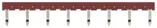


PYDN-15.5-080R
Relay Accessory, 8 Pole, Red, Short Bar
- Manufacturer: OMRON INDUSTRIAL AUTOMATION
- Product type: Other Relay Accessories
- Accessory Type:Short Bar; For Use With:-; Product Range:PYF, P2RF series; SVHC:No SVHC (17-Dec-2015)
- SVHC: No SVHC (17-Dec-2015)
- For Use With: -
- Product Range: -
- Accessory Type: Short Bar
| Delivery and price | |
|---|---|
| Units per pack | 50 |
| Price | 4.72 € |
| Current stock | 10+ |
| Lead time | 30 days |
## **Push-In Plus technology Sockets PYF-@@-PU/P2RF-@@-PU** ## **Sockets with Push-In Plus technology to Save Work Added to Series for MY and G2R-S Relays** - Push-In Plus technology are used to save wiring work in comparison with traditional screw terminals. (Wiring time is reduced by 60%* in comparison with traditional screw terminals.) - No screw loosening means maintenance-free application. - Light insertion force and strong pull-out strength to achieve both less wiring work and high reliability. - ‘Hand-free’ structure that holds an inserted screwdriver to achieve easier wiring work for stranded wires. - Two wires can be independently inserted into each terminal hole. - DIN Track mounting or screw mounting. For the most recent information on models that have been certified for safety standards, refer to your OMRON website. - According to OMRON actual measurement data from November 2015. Refer to _Safety Precautions_ on page 6. ## **Features** - Coil terminals and contact terminals are completely separated in an organized wiring layout. - A Release Lever is provided as a standard feature. - DIN terminal numbers are indicated. - The double fixture rail with DIN hook tabs attached to the top and bottom lets you mount the socket from either the top or bottom. - Front-in short bar enables easy installation without interference in duct when wiring. - Please refer short bar correspondence table in page 5 for further information of short bar. - There are screw mounting holes in the DIN hooks on the PYF-@@-PU and P2RF-@@-PU. Pull out the DIN hook tabs to mount the Sockets with screws. **==> picture [224 x 148] intentionally omitted <==** **----- Start of picture text -----**<br> DIN hook tab (the fixture rail)<br>Contact terminals (commons)<br>Contact short bar insertion holes<br>Double<br>NO contact terminals<br>fixture<br>NC contact terminals rails<br>Release lever<br>(standard feature)<br>Coil short bar insertion holes<br>Back of Push-In Plus<br>Coil terminals technology Socket<br>**----- End of picture text -----**<br> The fixture rails can be pulled out to mount the Relays with screws. **1** **PYF-@@-PU/P2RF-@@-PU** **Ordering Information** ## **Sockets** |**Applicable model (typical example)**|**Applicable model (typical example)**||**Socket**|**Socket**| |---|---|---|---|---| ||||**No. of poles**|**Model***| |General Purpose Relays|MY Series|MY2|2|**PYF-08-PU**| |||MY4|4|**PYF-14-PU**| |Timers|H3Y Series<br>H3YN Series|H3Y(N)-2-B|2|**PYF-08-PU-L**| |||H3Y(N)-4-B|4|**PYF-14-PU-L**| |General Purpose Relays|G2R-@-S (S) Series|G2R-1-S (S)|1|**P2RF-05-PU**| |Timers|H3RN Series|H3RN-1-B||| |General Purpose Relays|G2R-@-S (S) Series|G2R-2-S (S)|2|**P2RF-08-PU**| |Timers|H3RN Series|H3RN-2-B||| |Liquid Leakage Sensors|K7L Series|K7L-@B||| **Note:** Refer to your OMRON website for information on other applicable models of the _Products Related to Common Sockets and DIN Tracks_ . * The PYF-@@-PU-L Sockets do not have release levers. ## **Accessories (Order Separately)** ## **Short Bars** |**Pitch**|**Applicable models**|**No. of poles**|**Colors**|**Model***|**Minimum order (quantity)**| |---|---|---|---|---|---| |7.75 mm|PYF-@@-PU and<br>P2RF-@@-PU|2|Red (R)<br>Blue (S)<br>Yellow (Y)|**PYDN-7.75-020@**<br>**PYDN-7.75-030@**<br>**PYDN-7.75-040@**<br>**PYDN-7.75-200@**<br>**PYDN-31.0-080@**<br>**PYDN-15.5-080@**|10| |||3|||| |||4|||| |||20|||| |31.0 mm|PYF-@@-PU|8|||| |15.5 mm|P2RF-@@-PU|8|||| **Note:** Use the Short Bars for crossover wiring within one Socket or between Sockets. * Replace the box (@) in the model number with the code for the covering color. ## **Labels** |**Applicable models**|**Model**|**Minimum order**<br>**(sheet)**<br>**(quantity per sheet)**<br>5<br>(1 sheet/60 pieces)| |---|---|---| |PYF-@@-PU and<br>P2RF-@@-PU|**XW5Z-P4.0LB1**|| ## **Parts for DIN Track Mounting** |**Type**|**Type**|**Model**|**Minimum order (quantity)**| |---|---|---|---| |DIN Tracks|1 m|**PFP-100N**|---| ||0.5 m|**PFP-50N**|| |End Plate*||**PFP-M**|10| |Spacer||**PFP-S**|| Refer to your OMRON website for details on the PFP-@. - When mounting DIN rail, please use End Plate (Model PFP-M). ## **Ratings/Characteristics** ## **Characteristics** ## **PYF-@@-PU(-L)** |**Item**<br>**Model**|**Item**<br>**Model**|**PYF-08-PU (-L)**| |---|---|---| |**Ambient operating temperature**||| |**Ambient operating humidity**||| |**Continuous carry current** *||10 A| |**Dielectric**<br>**strength**|**Between contact terminals**<br>**of same polarity**|2,000 VAC, 1 min| ||**Between contact terminals**<br>**of different polarity**|2,000 VAC, 1 min| ||**Between coil and**<br>**contact terminals**|2,000 VAC, 1 min| |**Insulation resistance**||| |**Weight (approx.)**||80 g| - The continuous carry current of 10 A for PYF-08-PU(-L) is for an ambient temperature of 55°C. At an ambient temperature of 70°C, the value is 7 A. ## **P2RF-@@-PU** |**Item**<br>**Model**|**Item**<br>**Model**|**P2RF-05-PU**|**P2RF-08-PU**| |---|---|---|---| |**Ambient operating temperature**||~~~~40 to 70°C|| |**Ambient operating humidity**||5 to 85%|| |**Continuous carry current** *||10 A|6 A| |**Dielectric**<br>**strength**|**Between contact terminals**<br>**of same polarity**|1,000 VAC, 1 min|1,000 VAC, 1 min| ||**Between contact terminals**<br>**of different polarity**|---|3,000 VAC, 1 min| ||**Between coil and**<br>**contact terminals**|4,000 VAC, 1 min|4,000 VAC, 1 min| |**Insulation resistance**||1,000 Mmin. (at 500 VDC)|| |**Weight (approx.)**||40 g|45 g| - The continuous carry current of 10 A for P2RF-05-PU is for an ambient temperature of 55°C. At an ambient temperature of 70°C, the value is 7 A. The continuous carry current of 6 A for P2RF-08PU is for an ambient temperature of 55°C. At an ambient temperature of 70°C, the value is 5 A. ## **Applicable Standards** - UL 508, CSA C22.2 No.14, TÜV (EN 61984) **Note:** The continuous carry current of the PYF-08-PU and P2RF-05-PU for TÜV certification is 10 A at an ambient temperature of 55°C and 7 A at an ambient temperature of 70°C. The continuous carry current of the P2RF-08-PU for TÜV certification is 6 A at an ambient temperature of 55°C and 5 A at an ambient temperature of 70°C. **2** **PYF-@@-PU/P2RF-@@-PU** **Dimensions** **(Unit: mm)** ## **Sockets** ## **PYF-08-PU(-L)** **==> picture [413 x 251] intentionally omitted <==** **----- Start of picture text -----**<br> 71.5 max.<br>Terminal Arrangement/<br>Internal Connection Diagram<br>52.1 (TOP VIEW)<br>A1 A2<br>67.5 (13) (14) Mounting Hole<br>30.8 Dimensions<br>28.1 (4.2)<br>27.6<br>Two M4 screw<br>holes or<br>two 4-dia. holes<br>108<br>35.5 Release lever * 90 max. 12 42<br>(1) (4)<br>14 44<br>(5) (8)<br>27.25 11 41<br>(9) (12)<br>27.6 Note: The numbers in Note: Pull out the hooks to mount the<br>3.9 36.3 31 max . (4.2) parentheses are Relay with screws.<br>45 traditionally used<br>terminal numbers.<br>**----- End of picture text -----**<br> - The PYF-08-PU-L Sockets do not have release levers. **==> picture [47 x 8] intentionally omitted <==** **----- Start of picture text -----**<br> PYF-14-PU<br>**----- End of picture text -----**<br> **==> picture [413 x 243] intentionally omitted <==** **----- Start of picture text -----**<br> 71.5 max.<br>Terminal Arrangement/<br>Internal Connection Diagram<br>(TOP VIEW)<br>A1 A2<br>52.1 (13) (14)<br>67.5 Mounting Hole<br>30.8 Dimensions<br>28.1<br>(4.2)<br>27.6<br>Two M4 screw<br>holes or<br>two 4-dia. holes<br>12 22 32 42<br>(1) (2) (3) (4) 108<br>35.5 90 max. 14 24 34 44<br>Release lever * (5) (6) (7) (8)<br>11 21 31 41<br>(9) (10) (11) (12)<br>27.25<br>Note: The numbers in<br>27.636.3 31 max. (4.2) parentheses are traditionally used Note: Pull out the hooks to mount the Relay with screws.<br>3.9 terminal numbers.<br>45<br>**----- End of picture text -----**<br> - The PYF-14-PU-L Sockets do not have release levers. ## **Mounting Heights** ## **PYF-08-PU** ## **PYF-14-PU** **==> picture [318 x 96] intentionally omitted <==** **----- Start of picture text -----**<br> MY MY<br> 67.5 64.1 67.5 64.1<br> 28.1 28.1<br> (3.9) (3.9)<br>**----- End of picture text -----**<br> **3** **PYF-@@-PU/P2RF-@@-PU** ## **P2RF-05-PU** **==> picture [394 x 221] intentionally omitted <==** **----- Start of picture text -----**<br> 56.5 max.<br>Terminal Arrangement/<br>Internal Connection Diagram<br>(TOP VIEW)<br>A2 A1<br>52.4 (1) (5) Mounting Hole<br>28.1 Dimensions<br>27.6 (3)<br>Two M4 screw<br>holes or<br>two 4-dia. holes<br>108<br>35.5 Release lever 90 max. 12<br>(2)<br>14<br>(3)<br>27.25 11<br>(4)<br>Note: The numbers in<br>27.6 (3) parentheses are Note: Pull out the hooks to mount the<br>36.3 Relay with screws.<br>3.9 45 15.5 max. traditionally used terminal numbers.<br>52.1<br>**----- End of picture text -----**<br> ## **P2RF-08-PU** **==> picture [394 x 223] intentionally omitted <==** **----- Start of picture text -----**<br> 56.5 max .<br>Terminal Arrangement/<br>Internal Connection Diagram<br>(TOP VIEW)<br>A2 A1<br>52.4 (1) (8) Mounting Hole<br>28.1 Dimensions<br>27.6 (3)<br>Two M4 screw<br>holes or<br>two 4-dia. holes<br>108<br>35.5 Release lever 90 max. 12 22<br>(2) (7)<br>14 24<br>(4) (5)<br>27.25 11 21<br>(3) (6)<br>27.6 (3) Note: The numbers in Note: Pull out the hooks to mount the<br>3.9 36.345 15.5 max. parentheses are traditionally used Relay with screws.<br>52.1 terminal numbers.<br>**----- End of picture text -----**<br> ## **Mounting Heights** **==> picture [53 x 7] intentionally omitted <==** **----- Start of picture text -----**<br> P2RF-05-PU<br>**----- End of picture text -----**<br> **==> picture [52 x 7] intentionally omitted <==** **----- Start of picture text -----**<br> P2RF-08-PU<br>**----- End of picture text -----**<br> **==> picture [317 x 85] intentionally omitted <==** **----- Start of picture text -----**<br> G2R-@-S (S) G2R-@-S (S)<br>63.6 63.6<br> 28.1 28.1<br> (3.9) (3.9)<br>**----- End of picture text -----**<br> **4** **PYF-@@-PU/P2RF-@@-PU** ## **Accessories (Order Separately)** ## **Short Bars** |**ars**<br>||||||||| |---|---|---|---|---|---|---|---|---| |3.90<br>1.57<br>12<br>~~L~~<br>18.5<br>1.57<br>3.90<br>18.5<br>12<br>~~224.35~~<br>**5-@@ (7.75 mm)**<br>**.0-080@ (31mm)**|**Application**|**Pitch**|**Applicable**<br>**models**|**No. of**<br>**poles**|**L**<br>**(Length)**|**Colors**|**Model***|**Maximum**<br>**carry**<br>**current**| ||For Contact<br>terminals<br>(common)|7.75 mm|PYF-@@-PU and<br>P2RF-@@-PU|2|15.1|Red (R)<br>Blue (S)<br>Yellow (Y)|**PYDN-7.75-020**@|20 A| |||||3|22.85||**PYDN-7.75-030**@|| |||||4|30.6||**PYDN-7.75-040**@|| |||||20|154.6||**PYDN-7.75-200**@|| ||For Coil<br>terminals|31 mm|PYF-@@-PU|8|224.35||**PYDN-31.0-080**@|| |||15.5 mm|P2RF-@@-PU|8|115.85||**PYDN-15.5-080**@|| ||* Replace the box (@) in the model number with the code for the covering color.<br>**Note: 1.** Use the Short Bars for crossover wiring within one Socket or between Sockets.<br>**2.** When using short bar to coil terminals of PYF-@@-PU, make sure to use PYFDN-31.0-080@<br>(31mm).<br>When using short bar to coil terminals of P2RF-@@-PU, A1 terminal cannot be used.<br>In case crossover wiring of A1 terminal side is needed, crossover wiring using A1 terminals by<br>wire is possible.|||||||| |~~.~~||||||||| ## **Short bar correspondence table** **==> picture [119 x 77] intentionally omitted <==** **----- Start of picture text -----**<br> PYDN-15.5-080@ (15.5mm)<br>3.90<br>115.85<br>18.5<br>12<br>2.25 1.57<br>**----- End of picture text -----**<br> ||**Contact terminal**<br>**(Common)**|**Coil terminal**|**Coil terminal**| |---|---|---|---| |||**A1**|**A2**| |PYF-@@-PU|Available|❍|❍| |P2RF-@@-PU|Available|---|❍| ## **Parts for DIN Track Mounting** Refer to your OMRON website for details on the PFP-@. **5** **PYF-@@-PU/P2RF-@@-PU** ## **Safety Precautions** **Be sure to read the** _**Common Precautions for All Relays**_ **in the website at the following URL: http://www.ia.omron.com/.** ## **Warning Indications** **Indicates a potentially hazardous situation which, if not avoided, will result WARNING in minor or moderate injury, or may result in serious injury or death. Additionally there may be significant property damage. Precautions for Supplementary comments on what to do Safe Use or avoid doing, to use the product safely. Supplementary comments on what to do Precautions for or avoid doing, to prevent failure to Correct Use operate, malfunction, or undesirable effects on product performance.** ## **Meaning of Product Safety Symbols** **Used to warn of the risk of electric shock under specific conditions.** ## **Precautions for Safe Use Transportation** - Do not use a Socket that has fallen to the floor or ground. The performance of a Socket that has been dropped may be reduced. - • Do not drop the Socket or subject it to abnormal vibration or shock during transportation or mounting. Doing so may result in deterioration of performance, malfunction, or failure. - Do not transport a Socket when it is not packaged. Damage or failure may occur. ## **Operating and Storage Environments** - Do not use or store Sockets in the following locations. Doing so may result in deterioration of performance. - Locations subject to ambient storage temperatures outside the range • 40 to 70°C - Locations subject to relative humidity outside the range 5% to 85% - Locations subject to high temperature or high humidity - Locations in which condensation may occur due to rapid changes in temperature ## **WARNING** **Make sure that the Socket does not have an electrical charge before you perform wiring or maintenance work. Electrical shock may occur.** - Do not use or store Sockets in environments that contain silicone gas, sulfidizing gas (e.g., SO2 or H2S), or organic gas, or near materials that contain silicone. Doing so may cause the contacts to be unstable or to fail. - Do not use a Socket in a location subject to ultraviolet light (such as a location subject to direct sunlight). Printing may fade, the Socket may rust or corrode, and plastic parts may deteriorate. - Before you start wiring, make sure that the Socket is securely attached and mounted to a DIN Track. If the Socket is not stable, it may fall and possibly injure a worker. - Insert the flat-blade screwdriver fully to the bottom of the release hole. If the flat-blade screwdriver is not inserted correctly, the wire may not be connected correctly. - If there is lubrication, such as oil, on the tip of the flat-blade screwdriver, the flat-blade screwdriver may fall and possibly injure a worker. - When crossover wiring by wire and short bar, make sure not to insert wrong position, it may cause short circuit, malfunction or failure. ## **Push-In Plus technology** - Do not attempt to wire anything to the release holes. - When you insert a flat-blade screwdriver into a release hole, do not tilt or twist the screwdriver. The terminal may be damaged. - Insert a screwdriver into the release holes at an angle. The terminal may be damaged if the screwdriver is inserted straight in. - Do not allow the flat-blade screwdriver to fall when you are holding it in a release hole. - Do not bend a wire past its natural bending radius or pull on it with excessive force. Doing so may break the wires. - Do not insert more than one wire into each terminal insertion hole. - To prevent wire materials from smoking or igniting, use the wiring materials given in the following table. |**Recommended wires**|**Stripping length**|**Stripping length**| |---|---|---| ||**Ferrules used**|**Ferrules not**<br>**used**| |0.5 to 1.5 mm2/AWG20 to AWG16<br>(Ferrules: 0.5 to 1.0 mm2/AWG 20 to<br>AWG 18)|10 mm|8 mm| **Note:** Please use Ferrules with UL certification (R/C). ## **Disposal** - If you dispose of any Sockets, do not place them in a fire. **6** **PYF-@@-PU/P2RF-@@-PU** ## **Precautions for Correct Use** - Do not transport the Socket under the following conditions. Doing so may occasionally result in damage, malfunction, or deterioration of performance characteristics. - Locations subject to high temperature or high humidity ## **Checking Connections** - After the insertion, pull gently on the wire to make sure that it will not come off and the wire is securely fastened to the terminal. - To prevent short circuits, insert the stripped part of a stranded or solid wire or the conductor part of a ferrule until it is hidden inside the terminal insertion hole. (See the following diagram.) - Locations subject to condensation due to rapid changes in temperature - Do not use or store the Socket in the following locations. Doing so may occasionally result in damage, malfunction, or deterioration of performance characteristics. - Locations subject to shock or vibration - Do not use the Socket in a location where it may be subjected to solvents or alkali liquids. - Do not insert short bar in the hole for wire or screw driver, it may cause the result of failure of pull out. If insert short bar in the hole for wire or screw driver and try to pull out, it may cause damage for short bar or socket. ## **Push-In Plus technology 1. Connecting Wires to the Push-In Plus Terminal Part Names of the Terminal** **==> picture [62 x 17] intentionally omitted <==** **----- Start of picture text -----**<br> Release hole<br>Terminal (Insertion) hole<br>**----- End of picture text -----**<br> ## **2. Removing Wires from the Terminal** Use the following procedure to remove wires from the terminal. The same method is used to remove stranded wires, solid wires, and ferrules. **1.** Hold a flat-blade screwdriver at an angle and insert it into the release hole. **2.** With the flat-blade screwdriver still inserted into the release hole, remove the wire from the terminal insertion hole. **3.** Remove the flat-blade screwdriver from the release hole. **==> picture [162 x 64] intentionally omitted <==** **----- Start of picture text -----**<br> Flat-blade screwdriver<br>1 3<br>3 1<br>10 to 15°<br>2 2<br>Wire<br>**----- End of picture text -----**<br> ## **3. Recommended Ferrules and Crimp Tools Recommended ferrules** ## **Connecting Wires with Ferrules and Solid Wires** Insert the solid wire or ferrule straight into the terminal until the end strikes the terminal. **==> picture [65 x 46] intentionally omitted <==** **----- Start of picture text -----**<br> Release hole<br>Terminal (Insertion) hole<br>Ferrules<br>and solid wires<br>**----- End of picture text -----**<br> - If a wire is difficult to connect because it is too thin, use a flat-blade screwdriver in the same way as when connecting stranded wire. ## **Connecting Stranded Wires** Use the following procedure to connect the wires to the terminal. **1.** Hold a flat-blade screwdriver at an angle and insert it into the release hole. |**(mm2)**<br>**(AWG)**|**(mm2)**<br>**(AWG)**|**Phoenix**<br>**Contact**<br>**product**|**Weidmuller**<br>**product**|**Wago product**| |---|---|---|---|---| |0.5<br>20|8<br>|AI0.5-8<br>|H0.5/14|FE-0.5-8N-WH| |0.75<br>18|8<br>|AI0.75-8<br>|H0.75/14|FE-0.75-8N-GY| |1<br>18|8<br>|AI1-8<br>|H1.0/14|FE-1.0-8N-RD| - *1. Make sure that the outer diameter of the wire coating is smaller than the inner diameter of the insulation sleeve of the recommended ferrule. - *2. Make sure that the ferrule processing dimensions conform to the following figures. **==> picture [97 x 37] intentionally omitted <==** **----- Start of picture text -----**<br> 8 mm<br>2.1 mm max. 2.7 mm max.<br>**----- End of picture text -----**<br> - The angle should be between 10° and 15°. If the flat-blade screwdriver is inserted correctly, you will feel the spring in the release hole. **2.** With the flat-blade screwdriver still inserted into the release hole, insert the wire into the terminal hole until it strikes the terminal. **3.** Remove the flat-blade screwdriver from the release hole. **==> picture [203 x 58] intentionally omitted <==** **----- Start of picture text -----**<br> Flat-blade screwdriver<br>1 3 3 1<br>10 to 15°<br>2<br>2 Standed wires<br>**----- End of picture text -----**<br> **7** **PYF-@@-PU/P2RF-@@-PU** ## **Recommended Flat-blade Screwdriver** Use a flat-blade screwdriver to connect and remove wires. Use the following flat-blade screwdriver. The following table shows manufacturers and models as of 2015/Dec. |**Recommended Flat-blade Screwdriver**<br>Use a flat-blade screwdriver to connect and remove wires.<br>Use the following flat-blade screwdriver.<br>The following table shows manufacturers and models as of 2015/Dec.|**Recommended Flat-blade Screwdriver**<br>Use a flat-blade screwdriver to connect and remove wires.<br>Use the following flat-blade screwdriver.<br>The following table shows manufacturers and models as of 2015/Dec.| |---|---| |Side<br>0.4 mm<br>2.5 mm dia.<br>2.5 mm<br>Front|| |**Model**|**Manufacturer**| |XW4Z-00B|Omron| |ESD 0.40✕2.5|Wera| |SZF 0.4✕2.5|Phoenix Contact| |0.4✕2.5✕75 302|Wiha| |AEF.2.5✕75|Facom| |210-719|Wago*1| |SDI 0.4✕2.5✕75|Weidmuller*1| |98 20 25|KNIPEX*1| - *1. Insulated types of Flat-blade Screw driver, strongly recommended to prevent from an electric shock. **8** ## **Terms and Conditions Agreement** ## **Read and understand this catalog.** Please read and understand this catalog before purchasing the products. Please consult your OMRON representative if you have any questions or comments. ## **Warranties.** (a) Exclusive Warranty. Omron’s exclusive warranty is that the Products will be free from defects in materials and workmanship for a period of twelve months from the date of sale by Omron (or such other period expressed in writing by Omron). Omron disclaims all other warranties, express or implied. (b) Limitations. OMRON MAKES NO WARRANTY OR REPRESENTATION, EXPRESS OR IMPLIED, ABOUT NON-INFRINGEMENT, MERCHANTABILITY OR FITNESS FOR A PARTICULAR PURPOSE OF THE PRODUCTS. BUYER ACKNOWLEDGES THAT IT ALONE HAS DETERMINED THAT THE PRODUCTS WILL SUITABLY MEET THE REQUIREMENTS OF THEIR INTENDED USE. Omron further disclaims all warranties and responsibility of any type for claims or expenses based on infringement by the Products or otherwise of any intellectual property right. (c) Buyer Remedy. Omron’s sole obligation hereunder shall be, at Omron’s election, to (i) replace (in the form originally shipped with Buyer responsible for labor charges for removal or replacement thereof) the non-complying Product, (ii) repair the non-complying Product, or (iii) repay or credit Buyer an amount equal to the purchase price of the non-complying Product; provided that in no event shall Omron be responsible for warranty, repair, indemnity or any other claims or expenses regarding the Products unless Omron’s analysis confirms that the Products were properly handled, stored, installed and maintained and not subject to contamination, abuse, misuse or inappropriate modification. Return of any Products by Buyer must be approved in writing by Omron before shipment. Omron Companies shall not be liable for the suitability or unsuitability or the results from the use of Products in combination with any electrical or electronic components, circuits, system assemblies or any other materials or substances or environments. Any advice, recommendations or information given orally or in writing, are not to be construed as an amendment or addition to the above warranty. See http://www.omron.com/global/ or contact your Omron representative for published information. ## **Limitation on Liability; Etc.** OMRON COMPANIES SHALL NOT BE LIABLE FOR SPECIAL, INDIRECT, INCIDENTAL, OR CONSEQUENTIAL DAMAGES, LOSS OF PROFITS OR PRODUCTION OR COMMERCIAL LOSS IN ANY WAY CONNECTED WITH THE PRODUCTS, WHETHER SUCH CLAIM IS BASED IN CONTRACT, WARRANTY, NEGLIGENCE OR STRICT LIABILITY. Further, in no event shall liability of Omron Companies exceed the individual price of the Product on which liability is asserted. ## **Suitability of Use.** Omron Companies shall not be responsible for conformity with any standards, codes or regulations which apply to the combination of the Product in the Buyer’s application or use of the Product. At Buyer’s request, Omron will provide applicable third party certification documents identifying ratings and limitations of use which apply to the Product. This information by itself is not sufficient for a complete determination of the suitability of the Product in combination with the end product, machine, system, or other application or use. Buyer shall be solely responsible for determining appropriateness of the particular Product with respect to Buyer’s application, product or system. Buyer shall take application responsibility in all cases. NEVER USE THE PRODUCT FOR AN APPLICATION INVOLVING SERIOUS RISK TO LIFE OR PROPERTY OR IN LARGE QUANTITIES WITHOUT ENSURING THAT THE SYSTEM AS A WHOLE HAS BEEN DESIGNED TO ADDRESS THE RISKS, AND THAT THE OMRON PRODUCT(S) IS PROPERLY RATED AND INSTALLED FOR THE INTENDED USE WITHIN THE OVERALL EQUIPMENT OR SYSTEM. ## **Programmable Products.** Omron Companies shall not be responsible for the user’s programming of a programmable Product, or any consequence thereof. ## **Performance Data.** Data presented in Omron Company websites, catalogs and other materials is provided as a guide for the user in determining suitability and does not constitute a warranty. It may represent the result of Omron’s test conditions, and the user must correlate it to actual application requirements. Actual performance is subject to the Omron’s Warranty and Limitations of Liability. ## **Change in Specifications.** Product specifications and accessories may be changed at any time based on improvements and other reasons. It is our practice to change part numbers when published ratings or features are changed, or when significant construction changes are made. However, some specifications of the Product may be changed without any notice. When in doubt, special part numbers may be assigned to fix or establish key specifications for your application. Please consult with your Omron’s representative at any time to confirm actual specifications of purchased Product. ## **Errors and Omissions.** Information presented by Omron Companies has been checked and is believed to be accurate; however, no responsibility is assumed for clerical, typographical or proofreading errors or omissions. **OMRON Corporation Industrial Automation Company Authorized Distributor: Kyoto, JAPAN** **Contact: www.ia.omron.com** _**Regional Headquarters**_ **OMRON EUROPE B.V. OMRON ELECTRONICS LLC** Wegalaan 67-69, 2132 JD Hoofddorp 2895 Greenspoint Parkway, Suite 200 The Netherlands Hoffman Estates, IL 60169 U.S.A. Tel: (31)2356-81-300/Fax: (31)2356-81-388 Tel: (1) 847-843-7900/Fax: (1) 847-843-7787 **OMRON ASIA PACIFIC PTE. LTD.** No. 438A Alexandra Road # 05-05/08 (Lobby 2), Alexandra Technopark, Singapore 119967 Tel: (65) 6835-3011/Fax: (65) 6835-2711 **OMRON (CHINA) CO., LTD.** Room 2211, Bank of China Tower, 200 Yin Cheng Zhong Road, PuDong New Area, Shanghai, 200120, China Tel: (86) 21-5037-2222/Fax: (86) 21-5037-2200 © OMRON Corporation 2016 All Rights Reserved. In the interest of product improvement, specifications are subject to change without notice. **Cat. No. J212-E2-01A-X** 0316(0316)
Updated at June 7, 2026
With a legacy spanning over 80 years, Omron Industrial Automation is a globally recognized leader in the manufacture of advanced industrial control and automation components. Renowned for their reliability and engineering excellence, Omron delivers comprehensive solutions that enhance efficiency, machine safety, and precision across a wide range of manufacturing environments. Our extensive portfolio of Omron products is heavily focused on their industry-leading sensing and switching technologies. We offer a vast selection of sensors, excelling specifically in high-performance proximity sensors, light sensors, and temperature sensors. Complementing this range are robust switching solutions, featuring a deep inventory of power relays, solid-state relays, safety relays, and essential relay accessories designed for demanding operational requirements. Beyond sensing and switching, Omron is highly regarded for its precision automation and process control equipment. Our selection features highly accurate temperature controllers, versatile process controllers, and sophisticated panel displays and instrumentation. To support these fundamental systems, we also supply dependable Omron power supplies, notably AC/DC converters, alongside vital connectivity components like DIN rail terminal blocks to ensure secure, efficient, and complete industrial setups.
About Novapart
Novapart is a B2B electronic component broker specialising in stock shortages and cost reduction. We source hard-to-find parts and identify compliant alternatives across a catalogue of 410,000+ components from 500+ manufacturers.
Learn more →Stock Shortage Specialist
When a component is unavailable, discontinued or has an unacceptable lead time, we tap into our network of vetted European and Asian distributors to source what you need — without compromising on quality or traceability.
Request a quote →Compliant Alternatives
We identify pin-to-pin, electrically equivalent substitutes that meet the same certifications (RoHS, AEC-Q100, REACH) as your original specification — validated against datasheets, not just part numbers. Often at a lower cost.
BOM Analysis service →