
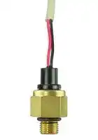


PX3EG1BS016BSAAX
PRESSURE SENSOR, 16BAR, G 1/4
- Manufacturer: HONEYWELL
- Product type: Pressure Transducers
- Port Style: G1/4
- Product Range: PX3 Series
- Sensor Output: Ratiometric
- Supply Current: 3mA
- Voltage Rating: 5VDC
- Operating Pressure Max: 16bar
- Pressure Measurement Type: Sealed Gauge
| Delivery and price | |
|---|---|
| Units per pack | 100 |
| Price | 47.37 € |
| Current stock | 25+ |
| Lead time | 7 days |
Issue B

**Heavy Duty Pressure Transducers** PX3 Series, 1 bar to 50 bar | 15 psi to 700 psi

## **32313757**

## **Datasheet**

**Figure 2. PX3 Series External Freeze/Thaw Resistance**

- (Shown with mating connector. See Figure 5.)

- • Reduced current consumption: Helps to reduce energy costs, and enhances product life if used in battery driven systems.

- • Media compatibility: Common HFC (hydrofluorocarbon) refrigerants such as R410A and R134A, next generation low global warming potential (GWP) refrigerants such as R448A (Solstice[®] N40), R32 and R1234ZE, petroleum oils, lubricants, hydraulic fluids, brake fluids, air and water. For ammonia and ~~2~~ other corrosive media, see Honeywell’s SPT Series.

## **DESCRIPTION**

Honeywell’s PX3 Series Heavy Duty Pressure Transducers use piezoresistive sensing technology with ASIC (Application Specific Integrated Circuit) signal conditioning in a brass housing and Metri-Pack 150 or cable harness electrical connections The PX3 Series are fully calibrated and temperature compensated from -40 °C to 125 °C [-40 °F to 257 °F].

## **VALUE TO CUSTOMERS**

- Total Error Band (TEB) ±1.0 %FSS from -20 °C to 85 °C: Provides the most comprehensive, clear and meaningful indication of the sensor’s true measurement performance over a specified temperature range; small error promotes system uptime and efficiency. (See Figure 1.)

## **Figure 1. TEB Definition and Temperature Performance**

**==> picture [207 x 184] intentionally omitted <==**

**----- Start of picture text -----**<br>
All Possible Errors<br>Offset<br>Full Scale Span<br>Pressure Non-Linearity<br>Accuracy Total<br>Pressure Hysteresis BFSL Error<br>Pressure Non-Repeatability Band<br>Thermal Effect on Offset<br>Thermal Effect on Span<br>Thermal Hysteresis<br>3<br>Total Error Band<br>2<br>1<br>0<br>-1<br>-2<br>-3<br>-40 °C -20 °C 0 °C 85 °C 125 °C<br>[-40 °F] [-4 °F]  [32 °F] [185 °F] [257 °F]<br>Temperature (°C [°F])<br>Total Error Band (%FSS)<br>**----- End of picture text -----**<br>


- High insulation resistance and dielectric strength: Protect the user and sensor in high over-voltage situations, and ensures that the device is compliant with industry standards.

- High EMC performance: Operates reliably in the presence of electro-magnetic fields, such as near wireless signals, RF communication, and electrical devices.

- High external freeze/thaw resistance: Survives exposure to frost, commonly found in refrigeration systems. (See Figure 2.)

## **DIFFERENTIATION**

- Optional diagnostics mode: Beneficial in applications where the sensor functionality and the need to know internal or external failure modes is critical.

- Great customer value: Multiple configuration possibilities provide flexibility of use in the application with no upfront NRE or tooling charges.

- Durable: Provides the tough environmental specs needed, including insulation resistance and dielectric strength, freezethaw resistance (see Figure 2), and EMC performance.

## **FEATURES**

- Pressure range: 1 bar to 50 bar | 15 psi to 700 psi (absolute and sealed gage)

- Ratiometric output: 0.5 Vdc to 4.5 Vdc or 0.33 Vdc to 2.97 Vdc

- Fully calibrated and temperature compensated

- Total Error Band: ±1.0 %FSS from -20 °C to 85 °C [-4 °F to 185 °F]

- External freeze/thaw resistance: 6 cycles from -30 °C to 50 °C [-22 °F to 122 °F]

- Insulation resistance: >100 MOhm, 1500 Vdc

- Dielectric strength: AC1500V, 1 min. or AC1800V, 1 s

- Current consumption: 3.5 mA max.

- EMC (radiated immunity): 200 V/m per ISO 11452-2

- Ingress protection IP67 (Metri-Pack 150), IP69K (cable harness)

- Response time: <2 ms

- RoHS, REACH, and CE compliant

- Six industry-standard pressure port types, including a tube port which provides for hermetically-sealed process connection

## **POTENTIAL APPLICATIONS**

- Industrial: Refrigerant pressure monitoring in HVAC/R systems; air compressor system pressure

- Transportation: Air system monitoring; hydraulic oil pressure monitoring

## **PORTFOLIO**

Honeywell’s PX3 Series joins the PX2 Series, MLH Series, and SPT Series heavy duty pressure transducers.

Safety and Productivity Solutions

**Heavy Duty Pressure Transducers** PX3 Series, 1 bar to 50 bar | 15 psi to 700 psi

## **Table 1. Electrical Specifications**

**==> picture [542 x 154] intentionally omitted <==**

**----- Start of picture text -----**<br>
Characteristic Parameter<br>Supply voltage:<br>   5 Vdc ±0.25 Vdc<br>   3.3 Vdc ±0.25 Vdc<br>Over voltage and reverse voltage ±16 Vdc<br>Current consumption:<br>   5 Vdc supply 3.0 mA max.<br>   3.3 Vdc supply 1.6 mA to 2.1 mA<br>Short circuit protection yes<br>Nominal output transfer function:<br>   5 Vdc supply 0.5 Vdc to 4.5 Vdc (ratiometric to supply)<br>   3.3 Vdc supply 0.33 Vdc to 2.97 Vdc (ratiometric to supply)<br>**----- End of picture text -----**<br>


**Table 2. Performance Specifications (At 25 °C [77 °F] and under unless otherwise noted.)**

**==> picture [542 x 278] intentionally omitted <==**

**----- Start of picture text -----**<br>
Characteristic Parameter<br>Operating temperature range [1] -40 °C to 125 °C [-40 °F to 257 °F]<br>Storage temperature range [1] -40 °C to 125 °C [-40 °F to 257 °F]<br>Compensated temperature range -40 °C to 125 °C [-40 °F to 257 °F]<br>Total Error Band [2] :<br>   -20 °C to 85 °C [-4 °F to 185 °F] ±1.0 %FSS<br>   <-20 °C, >85 °C [<-4 °F, >185 °F] ±2.0 %FSS<br>Accuracy BFSL [3] ±0.25 %FSS<br>Response time <2 ms (10% to 90% step change in pressure)<br>Turn on time [4] <7 ms<br>EMC rating [5] :<br>   surge immunity (all leads) ±1000 V line to ground per IEC 61000-4-5<br>   electrostatic discharge ±4 kV contact, ±8 kV air per IEC 61000-4-2<br>   radiated immunity 10 V/m (80 MHz to 1000 MHz) per IEC 61000-4-3<br>   fast transient burst ±1 kV per IEC 61000-4-4<br>   immunity to conducted disturbances 3 V per IEC 61000-4-6<br>   radiated emissions 40 dB (30 MHz to 230 MHz), 47 dB (230 MHz to 1000 MHz) per CISPR 11<br>   radiated immunity 200 V/m per ISO 11452-2<br>Insulation resistance >100 MOhm, 1500 Vdc<br>Dielectric strength AC1500V, 1 min. or AC1800V, 1 s<br>Load resistance >5 kOhm<br>Life greater than 10 million full scale pressure cycles over the calibrated pressure range<br>**----- End of picture text -----**<br>


1 Dependent on external and internal seal and cable jacket materials. See Table 5 and Figure 5 for temperature range details.

2 Total Error Band: The maximum deviation from the ideal transfer function over the entire compensated temperature and pressure range. Includes all errors due to offset, full scale span, pressure non-linearity, pressure hysteresis, pressure non-repeatability, thermal effect on offset, thermal effect on span, and thermal hysteresis. See Figure 1.

3 Accuracy: The maximum deviation in output from a Best Fit Straight Line (BFSL) fitted to the output measured over the pressure range at 25 °C [77 °F]. Includes all errors due to pressure non-linearity, pressure hysteresis, and pressure non-repeatability. See Figure 1.

4 Turn on Time: Duration from power applied until first valid output.

5 Tested using 1.5 m [59.1 in] cable.

**Table 3. Pressure Reference Definitions**

**==> picture [542 x 102] intentionally omitted <==**

**----- Start of picture text -----**<br>
Pressure Reference Definition<br>Output is calibrated to be proportional to the difference between applied pressure and a fixed reference to<br>Absolute<br>perfect vacuum (absolute zero pressure).<br>Sensor construction is identical to the absolute version with a built in reference at zero pressure in order to<br>minimize measurement error over temperature. The output is calibrated to be proportional to the difference<br>Sealed gage [1]<br>between applied pressure and a reference of 1 standard atmosphere (1.013 barA | 14.7 psiA). Example: 100 psi<br>sealed gage has a calibrated pressure range from 14.7 psi absolute to 114.7 psi absolute. (See Figure 3.)<br>**----- End of picture text -----**<br>


1 Sealed gage option only available in pressure ranges at or above 8 bar | 100 psi.

**2** Safety and Productivity Solutions

**Heavy Duty Pressure Transducers** PX3 Series, 1 bar to 50 bar | 15 psi to 700 psi

## **Figure 3. Ratiometric Output Option AA for 100 psi, Absolute vs Sealed Gage**

**==> picture [255 x 197] intentionally omitted <==**

**----- Start of picture text -----**<br>
5<br>4.5<br>4<br>3.5<br>3<br>2.5<br>100 psi absolute<br>2<br>100 psi sealed gage<br>1.5<br>1<br>0.5<br>0<br>0 20 40 60 80 100 120 140<br>14.7 114.7<br>Pressure (psi Absolute)<br>Output (V)<br>**----- End of picture text -----**<br>


**Table 4. Pressure Ratings**

**==> picture [263 x 256] intentionally omitted <==**

**----- Start of picture text -----**<br>
bar psi<br>Operating  Over- Burst  Operating  Over- Burst<br>Pressure pressure Pressure Pressure pressure Pressure<br>1 5 8 15 70 115<br>1.6 5 8 30 150 250<br>2 10 17 50 250 400<br>2.5 10 17 100 450 750<br>4 17 27 150 450 750<br>6 31 51 200 450 1150<br>8 31 51 250 450 1150<br>10 31 51 300 1000 1500<br>16 32 80 500 1000 1500<br>20 69 103 600 1000 1500<br>25 69 103 667 1000 1500<br>35 69 103 700 1000 1500<br>40 69 103 - - -<br>46 69 103 - - -<br>50 69 103 - - -<br>**----- End of picture text -----**<br>


## **Diagnostics Mode**

The PX3 Series diagnostics mode allows the device to indicate when internal or external faults occur. If an internal fault occurs, the output will rail to the preset lower or upper limit values shown in Figure 4 and Table 5.

External faults will result in the sensor’s output exceeding those preset limits (lower or upper). (For example, if the external sensor ground (signal) were lost, the sensor output would exceed the upper rail of 97.5%.)

**Figure 4. Analog Output with Diagnostics**

**==> picture [251 x 151] intentionally omitted <==**

**----- Start of picture text -----**<br>
100<br>Upper Rail (97.5%)<br>90<br>80<br>70<br>60<br>50<br>40<br>30<br>20<br>10<br>Lower Rail (2.5%)<br>0<br>10 20 30 40 50 60 70 80 90 100<br>Pressure (psi)<br>Output (%Vsupply)<br>**----- End of picture text -----**<br>


**Table 5. Output Transfer Function Codes**

**==> picture [263 x 125] intentionally omitted <==**

**----- Start of picture text -----**<br>
Fault Condition Analog Diagnostic Rail<br>EEPROM Corrupt below lower rail<br>Sensor Bridge Open<br>above upper rail<br>(any element)<br>Sensor Bridge Short<br>above upper rail<br>(any element)<br>Low supply voltage below lower rail<br>Loss of ground<br>above upper rail<br>connection<br>**----- End of picture text -----**<br>


**3**

Safety and Productivity Solutions

**Heavy Duty Pressure Transducers** PX3 Series, 1 bar to 50 bar | 15 psi to 700 psi

**Table 6. Environmental and Mechanical Specifications**

**==> picture [541 x 291] intentionally omitted <==**

**----- Start of picture text -----**<br>
Characteristic Parameter<br>Shock:<br>threaded ports 100 G per MIL-STD-202G, Method 213B, Cond. F (at 25 °C [77 °F])<br>   tube port 100 G per MIL-STD-202F, Method 213B, and Condition C<br>Vibration:<br>threaded ports 20 G sweep, 10 Hz to 2000 Hz (at 25 °C [77 °F])<br>   tube port 10 Hz to 55 Hz, 2 mm displacement, tested as per IEC 60068-2-6; Test FC. (at 25°C [77°F])<br>Ingress protection:<br>   Metri-Pack 150 electrical connector IP67<br>   cable harness electrical connector IP69K<br>Ambient humidity 0 %RH to 95 %RH, non-condensing<br>External freeze/thaw resistance >6 cycles from -30 °C to 50 °C [-22 °F to 122 °F]<br>Wetted materials:<br>   threaded ports brass C36000 (lead (Pb) content: 3.7% max.)<br>   tube port copper UNS C12200 (lead (Pb) free)<br>   braze filler silver and copper alloy<br>   internal media seal seal material as required by the application (see seal material media compatibility options below)<br>   sensing element and substrate alumina, glass, silicon<br>   adhesives epoxy<br>Internal seal material media compatibility [1] :<br>   HNBR (option H) refrigerants, petroleum oils, lubricants<br>   silicone (option S) air, water, hydraulic fluids<br>Other materials:<br>   Metri-Pack 150 electrical connector PBT 30% GF<br>   external O-ring seal on G1, M1 ports nitrile (-30 °C to 125 °C [-22 °F to 257 °F])<br>**----- End of picture text -----**<br>


1 Honeywell can assist with selecting suitable seal material for the media based on the seal manufacturer’s recommendation. The customer should test the compatibility with the media to ensure that it is correct for the application.

## **CAUTION**

## **PRODUCT DAMAGE**

- Ensure torque specifications are determined for the specific application. Values provided are for reference only. (Mating

- materials and thread sealants can result in significantly different torque values from one application to the next.)

- When using mating parts made of stainless steel, use a thread sealant with anti-seize properties to prevent thread galling. Ensure the sealant is rated for the application.

- Use appropriate tools (such as an open ended wrench or deep well socket) to install transducers.

- Always hand-start transducers into the hole to prevent cross threading and damage.

- Ensure that torque is not applied to the electrical connector.

- Ensure that the proper mating electrical connector with a seal is used to connect the transducer. Improper or damaged seals can compromise ingress protection leading to short circuits.

**Failure to comply with these instructions may result in product damage.**

## **CAUTION**

## **PRODUCT DAMAGE TO TUBE PORT**

Ensure that the temperature of the brass port and plastic connector is maintained below 125 °C during flame brazing. Exposure to temperatures higher than 125 °C can cause permanent product damage and can compromise ingress protection leading to short circuits.

**Failure to comply with these instructions may result in product damage.**

**4** Safety and Productivity Solutions

**Heavy Duty Pressure Transducers** PX3 Series, 1 bar to 50 bar | 15 psi to 700 psi

## **Figure 5. Nomenclature and Order Guide** E

For example, **PX3AN1BS150PAAAX** defines a PX3 Series Heavy Duty Pressure Transducer, Metri-Pack 150, standard (UL V-0) electrical connector type, 1/4-18 NPT pressure port type, brass housing body, silicone: -40 °C to 125 °C [-40 °F to 257 °F] seal material and temperature range, 150 psi pressure range, absolute pressure reference, ratiometric: 0.5 Vdc to 4.5 Vdc output transfer function, no special

**==> picture [501 x 485] intentionally omitted <==**

**----- Start of picture text -----**<br>
|||||||||
|---|---|---|---|---|---|---|---|
|PX3  A   N1  B   S  150P  A  AA  X|
|Series|Special|
|X|
|Heavy Duty|
|PX3|
|Pressure Transducer|[1]|
|Output Transfer Function|
|AA|Ratiometric, 5.0 V: 10% to 90% Vs|
|Electrical Connector Type|[2]|DA|Ratiometric, 5.0 V: 10% to 90% Vs (diagnostics on)|[6]|
|AC|Ratiometric, 3.3 V: 10% to 90% Vs|
|a|A|Metri-Pack 150,Standard (UL V-0)|[3]|DC|Ratiometric, 3.3 V: 10% to 90% Vs (diagnostics on)|[6]|
|Pressure Reference|
|PVC Cable: 1 m [3.2 ft]|[4]|
|E|-40 °C to 100 °C|A|[Absolute]|
|[-40 °F to 212 °F]|S|[Sealed gage][7]|
|PVC Cable: 2 m [6.6 ft]|[4]|
|F|-40 °C to 100 °C|[3]|2|||||$=|Pressure Range|[3]|
|bar|psi|
|[-40 °F to 212 °F]|
|001B|1 bar|015P|15 psi|
|1.6B|1.6 bar|030P|30 psi|
|XLPE Cable: 1 m [3.2 ft]|[4]|002B|2 bar|050P|50 psi|
|M|-40 °C to 125 °C|
|[-40 °F to 257 °F]|2.5B|2.5 bar|100P|100 psi|
|004B|4 bar|150P|150 psi|
|006B|6 bar|200P|200 psi|
|XLPE Cable: 2 m [6.6 ft]|[4]|
|N|-40 °C to 125 °C|[3]|008B|8 bar|250P|250 psi|
|[-40 °F to 257 °F]|010B|10 bar|300P|300 psi|
|fb|016B|16 bar|~|500P|500 psi|
|020B|20 bar|600P|600 psi|
|025B|25 bar|667P|667 psi|
|Pressure Port Type|[5]|035B|35 bar|700P|700 psi|
|040B|40 bar|
|7/16-20 UNF|
|046B|46 bar|
|1/4 inch 45° Flare|
|F1|050B|50 bar|
|Female Schrader|
|(SAE J512)|
|Seal Material and Temperature Range|[2,8]|
|G1/4 A-G|[HNBR (Hydrogenated Nitrile Butadiene Rubber):]|
|G1|(ISO 1179-3)|-30|H|[°]|C to 125|[°]|C [-22 °F to 257 °F] (50 hr at 135 °C [257 °F)|
|S|[Silicone: -40 °C to 125 °C [-40 °F to 257 °F]]|
|M12 x 1.5|
|M1|
|(ISO 6149-3)|
|ry|
|N1|1/4-18 NPT|Mating Connector|[[3]]|
|N2|1/8-27 NPT|
|:|if|
|=|1 Not all catalog listing combinations are shown. Custom products areNot all catalog listing combinations are shown. Custom products are|
|T1|Tube|

**----- End of picture text -----**<br>


Mating Connector[[3]] 1 Not all catalog listing combinations are shown. Custom products areNot all catalog listing combinations are shown. Custom products are available. Please contact Honeywell.

2 Custom configurations such as varied cable lengths, end mating connectors, different O-ring materials, and different pressure ranges are available.

3 Metri-Pack 150 mating connectors with shielded cable and 22 AWG wire are available from Honeywell. Order part no. 3685301 for 1 m [9.8 ft] cable length and part no. 3685302 for 3 m [3.2 ft] cable length.

## **Housing Body Material**

**B**[Brass (C36000)]

4 PVC Flame Retardant (FR) type cable is FT1 rated per IEC60332-1; XLPE non-flame retardant cable is FT2 rated per IEC60332-1.

- 5 See Table 5 for pressure port materials.

- 6 See page 3 for Diagnostics Mode information.

- 7 Sealed gage option only available in pressure ranges at or above 8 bar | 100 psi.

- 8 See Table 5 for seal material media compatibility.

**5**

Safety and Productivity Solutions

**Heavy Duty Pressure Transducers** PX3 Series, 1 bar to 50 bar | 15 psi to 700 psi

## **Figure 6. Metri-Pack Mounting Dimensions (For reference only. mm/[in].)** E

**==> picture [540 x 669] intentionally omitted <==**

**----- Start of picture text -----**<br>
Pinout F1, G1, N1, N2, M1  T1 General<br>Pin A Pin A Pin A = Ground product<br>Pin B = Vsupply Yellow lettering<br>Pin C = Vout marking<br>22,0<br>[0.87]<br>Pin C Pin C Pin B<br>Pin B<br>F1: 7/16-20 UNF 1/4 inch 45° Flare Female Schrader (SAE J512) G1: G1/4 A-G (ISO 1179-3)<br>Seal: 45° cone Seal: nitrile O-ring (included)<br>Mating geometry: SAE J512 Mating geometry: ISO 1179-1<br>Installation torque: 17 N m [12.5 ft-lb] Installation torque: 50 N m [36.9 ft-lb]<br>Weight: 54,5 g [1.9 oz] ø17,0 Weight: 35,1 g [1.2 oz]<br>    [0.67]<br>ø17,0<br>    [0.67]<br>ø21,60<br>37,4     [0.85]<br>[1.47] [1.41]35,9     [0.85]ø21,60<br>49,6<br>[1.95] 15,4 1,85<br>[0.61] [47.1] 13,9<br>[0.55]<br>12,2<br>[0.48] 11,2<br>7/16-20 UNF 1/4 in 45° Flare  [0.44]<br>    [0.63]ø15,9 Female Schrader (SAE J512) G1/4 A-G (ISO 1179-3)<br>M1: M12 x 1.5 (ISO 6149-3) N1: 1/4-18 NPT<br>Seal: nitrile O-ring (included) Seal: Pipe thread<br>Mating geometry: ISO 6149-1 Mating geometry: ANSI B1.20.1<br>Installation torque: 25 N m [18.4 ft-lb] Installation torque: Two to three turns from finger tight<br>Weight: 33,9 g [1.2 oz] Weight: 35,1 g [1.2 oz]<br>    [0.67]ø17,0     [0.67]ø17,0<br>ø21,60 ø21,60<br>34,9   [0.85] 35     [0.85]<br>[1.37] [1.4]<br>[1.91]48,4 12,9 [2.0]50 13<br>[0.51] [0.5]<br>13,9 15,0<br>[0.53] [0.59]<br> M12 x 1.5 (ISO 6149-3) 1/4-18 NPT<br>N2: 1/8-27 NPT T1: Tube<br>ø17,0<br>Seal: Pipe thread Seal: Brazing     [0.67]<br>Mating geometry: ANSI B1.20.1 Weight: 32 g [1.1 oz]<br>Installation torque: Two to three turns from finger tight<br>Weight: 31,2 g [1.1 oz]<br>39,5<br>[1.56]<br>ø17,0<br>    [0.67]<br>96,5<br>[3.80]<br>ø23,0<br>ø21,60     [0.91]<br>36   [0.85]<br>[1.4] Ensure this area is<br>57,0  protected during the<br>46 [2.24]  brazing process so<br>[1.8] 14  do not exceed that temperatures<br>[0.5]  125 °C [257 °F].<br>7,0<br>10,0 [0.27]<br>[0.39] ø7,3<br>1/8-27 NPT     [0.29]<br>ø6,35<br>    [0.25]<br>**----- End of picture text -----**<br>


**6** Safety and Productivity Solutions

**Heavy Duty Pressure Transducers** PX3 Series, 1 bar to 50 bar | 15 psi to 700 psi

**Figure 7. Cable Harness Mounting Dimensions Shown by Pressure Port Type (For reference only. mm/[in].)** E

**==> picture [541 x 669] intentionally omitted <==**

**----- Start of picture text -----**<br>
Wire  F1, G1, N1, N2, M1  T1 General<br>colors  Black = Ground product<br>Red = Vsupply marking White label with<br>22,0 White = Vout black lettering<br>[0.87]<br>F1: 7/16-20 UNF 1/4 inch 45° Flare Female Schrader (SAE J512) G1: G1/4 A-G (ISO 1179-3)<br>Seal: 45° cone Seal: nitrile O-ring (included)<br>Mating geometry: SAE J512 Mating geometry: ISO 1179-1<br>Installation torque: 1000 ±50 Installation torque:<br>[39.9 ±1.9]<br>   17 N m [12.5 ft-lb]    50 N m [36.9 ft-lb] 1000 ±50<br>[39.9 ±1.9]<br>Weight: 90 g [3.2 oz] Weight: 70 g [2.5 oz]<br>ø21,6<br>    [0.85]<br>33,1     [0.85]ø21,6<br>[1.30]<br>31,6<br>[1.24]<br>45,3<br>[1.78] 15,4<br>[0.61] [1.683]42,75 [0.55]13,9<br>12,2 7/16-20 UNF 1/4 in 45° Flare<br>[0.48] Female Schrader (SAE J512) 11,2<br>[0.44] G1/4 A-G (ISO 1179-3)<br>ø15,9<br>    [0.63]<br>M1: M12 x 1.5 (ISO 6149-3) N1: 1/4-18 NPT<br>Seal: nitrile O-ring (included) Seal: Pipe thread<br>Mating geometry: Mating geometry:<br>   ISO 6149-1 1000 ±50    ANSI B1.20.1 [39.9 ±1.9]1000 ±50<br>Installation torque: [39.9 ±1.9] Installation torque:<br>   25 N m [18.4 ft-lb]    Two to three turns<br>Weight: 69 g [2.4 oz]]    from finger tight<br>Weight: 70 g [2.5 oz]<br>ø21,6 ø21,6<br>    [0.85] 30,6     [0.85]<br>30,6 [1.20]<br>[1.20]<br>[1.73]44,1 [0.51]12,9 [1.79]45,6 [0.51]12,9<br>13,5 15,0<br>[0.53]  M12 x 1.5 (ISO 6149-3) [0.59] 1/4-18 NPT<br>N2: 1/8-27 NPT T1: Tube<br>Seal: Pipe thread Seal: Brazing<br>Mating geometry:   Weight: 67 g [2.4 oz] [39.9 ±1.9]1000 ±50<br>   ANSI B1.20.1<br>Installation torque:  [39.9 ±1.9]1000 ±50<br>   Two to three turns<br>ø23,0<br>   from finger tight     [0.91]<br>Weight: 66 g [2.3 oz]<br>32,2<br>[1.38]<br>ø21,6<br>    [0.85]<br>[1.24]31,6 [3.63]92,2<br>41,6<br>[1.64] 13,9<br>[0.55] Ensure this area is<br>57,0  protected during the<br>[2.24]  brazing process so<br>10,0  that temperatures<br>[0.39] 1/8-27 NPT 7,0  do not exceed<br>[0.27]  125 °C [257 °F].<br>ø7,3<br>ø6,35     [0.29]<br>    [0.25]<br>**----- End of picture text -----**<br>


**7**

Safety and Productivity Solutions

## **ADDITIONAL INFORMATION**

The following associated literature is available on the Honeywell web site at sensing.honeywell.com:

- Product line guide

- Product range guide

- Product installation instructions

- Application notes:

- Heavy Duty Pressure Transducers, PX2 Series and PX3 Series

- PX2 Series and PX3 Series Heavy Duty Pressure Transducers for Potential Use in Industrial Refrigeration

- PX2 Series and PX3 Series Heavy Duty Pressure Transducers for Potential Use in Industrial HVAC/R Applications

- Technical notes:

- Total Error Band Specification for Honeywell Heavy Duty Pressure Transducers, PX2 Series and PX3 Series

- Media Compatibility for Honeywell Heavy Duty Pressure Transducers, PX2 Series and PX3 Series

## **WARNING PERSONAL INJURY**

DO NOT USE these products as safety or emergency stop devices or in any other application where failure of the product could result in personal injury.

**Failure to comply with these instructions could result in death or serious injury.**

## **WARNING**

## **MISUSE OF DOCUMENTATION**

- The information presented in this datasheet is for reference only. Do not use this document as a product installation guide.

- Complete installation, operation, and maintenance information is provided in the instructions supplied with each product.

**Failure to comply with these instructions could result in death or serious injury.**

- CAD models

## **Warranty/Remedy**

Honeywell warrants goods of its manufacture as being free of defective materials and faulty workmanship during the applicable warranty period. Honeywell’s standard product warranty applies unless agreed to otherwise by Honeywell in writing; please refer to your order acknowledgement or consult your local sales office for specific warranty details. If warranted goods are returned to Honeywell during the period of coverage, Honeywell will repair or replace, at its option, without charge those items that Honeywell, in its sole discretion, finds defective. **The foregoing is buyer’s sole remedy and is in lieu of all other warranties, expressed or implied, including those of merchantability and fitness for a particular purpose. In no event shall Honeywell be liable for consequential, special, or indirect damages.**

While Honeywell may provide application assistance personally, through our literature and the Honeywell web site, it is buyer’s sole responsibility to determine the suitability of the product in the application.

## **For more information**

Specifications may change without notice. The information we supply is believed to be accurate and reliable as of this writing. However, Honeywell assumes no responsibility for its use.

To learn more about Honeywell’s sensing and switching products, call 1.800.537.6945 , visit sensing.honeywell.com, or e-mail inquiries to info.sc@honeywell.com

## **Honeywell Safety and Productivity Solutions**

32313757-B-EN  |  10/16 © 2016 Honeywell International Inc. Solstice[®] N40 is a registered trademark Honeywell International Inc.

9680 Old Bailes Road Fort Mill, SC 29707 www.honeywell.com
Updated at February 9, 2023
Honeywell is a globally recognized leader in the design and manufacture of advanced sensing and switching solutions. Renowned for engineering components that deliver enhanced precision and ruggedness, Honeywell provides essential technologies for demanding applications across critical healthcare, aerospace, and industrial equipment. With a comprehensive portfolio built to address both basic and complex design challenges, the company stands at the forefront of reliable electronic component manufacturing. The core of our Honeywell offering is an extensive selection of high-performance sensors and transducers. This includes a robust lineup of pressure sensors and transducers engineered for accurate fluid and gas measurement in challenging environments. Furthermore, we provide a wide array of temperature sensors and specialized temperature sensing NTC thermistors designed for stable thermal management, alongside precision current sensors and load cells that deliver critical feedback for control systems. Beyond advanced sensing technology, Honeywell’s expertise extends to essential circuit protection and electromechanical components. Our selection encompasses power relays, thermal magnetic circuit breakers, and standard terminal blocks, ensuring safe and efficient power distribution. Whether integrating core components or sourcing specialized accessories, design engineers can rely on Honeywell for uncompromising quality and operational excellence.
About Novapart
Novapart is a B2B electronic component broker specialising in stock shortages and cost reduction. We source hard-to-find parts and identify compliant alternatives across a catalogue of 410,000+ components from 500+ manufacturers.
Learn more →Stock Shortage Specialist
When a component is unavailable, discontinued or has an unacceptable lead time, we tap into our network of vetted European and Asian distributors to source what you need — without compromising on quality or traceability.
Request a quote →Compliant Alternatives
We identify pin-to-pin, electrically equivalent substitutes that meet the same certifications (RoHS, AEC-Q100, REACH) as your original specification — validated against datasheets, not just part numbers. Often at a lower cost.
BOM Analysis service →