


PTGL13AR100H8B72B0
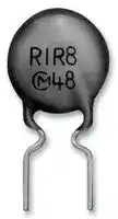
PTC Thermistor, 10 ohm, Through Hole, 265 V, -25% to +25%, POSISTOR PTGL Series
- Manufacturer: MURATA
- Product type: PTC Thermistors
- Applications: High Wattage Power Supply
- Product Range: POSISTOR PTGL
- Thermistor Mounting: Through Hole
- Operating Voltage Max: 265V
- Operating Temperature Max: 60°C
- Operating Temperature Min: -10°C
- Zero Power Resistance at 25°C: 10ohm
| Delivery and price | |
|---|---|
| Units per pack | 1 |
| Price | 2.53 € |
| Current stock | 10+ |
| Lead time | 30 days |
! Note

R90E.pdf 07.3.19

- This PDF catalog is downloaded from the website of Murata Manufacturing co., ltd. Therefore,  it’s specifications are subject to change or our products in it may be discontinued without advance notice. Please check with our sales representatives or product engineers before ordering.

- • This PDF catalog has only typical specifications because there is no space for detailed specifications. Therefore, please approve our product specifications or transact the approval sheet for product specifications before ordering.

**==> picture [101 x 18] intentionally omitted <==**

**----- Start of picture text -----**<br>
Murata<br>Manufacturing Co., Ltd.<br>**----- End of picture text -----**<br>


**Cat.No.R90E-9** |

! Note

R90E.pdf 07.3.19 **1 2 3 4 5 6 7 8 9 10 11**

> • This PDF catalog is downloaded from the website of Murata Manufacturing co., ltd. Therefore,  it’s specifications are subject to change or our products in it may be discontinued without advance notice. Please check with our ! Note[• Please read rating and ][!][CAUTION (for storage, operating, rating, soldering, mounting and handling) in this catalog to prevent smoking and/or burning, etc.] sales representatives or product engineers before ordering.• This catalog has only typical specifications because there is no space for detailed specifications. Therefore, please approve our product specifications or transact the approval sheet for product specifications before ordering. • This PDF catalog has only typical specifications because there is no space for detailed specifications. Therefore, please approve our product specifications or transact the approval sheet for product specifications before ordering.

|**CONTENTS**<br>**POSISTOR**r**and "POSISTOR" in this**|**CONTENTS**<br>**POSISTOR**r**and "POSISTOR" in this**|**CONTENTS**<br>**POSISTOR**r**and "POSISTOR" in this**|**CONTENTS**<br>**POSISTOR**r**and "POSISTOR" in this**|**CONTENTS**<br>**POSISTOR**r**and "POSISTOR" in this**|**CONTENTS**<br>**POSISTOR**r**and "POSISTOR" in this**|**catalog are**|**catalog are**||
|---|---|---|---|---|---|---|---|---|
|**the trademarks**|||**of Murata Manufacturing**||||**Co., Ltd.**||
|**Part Numbering**||||||||2|
||||||||||
|**Basic Characteristics of POSISTOR**r||||||||4|
||||||||||
|**Selection Guide**||||||||6|
||||||||||
|**Application Matrix**||||||||7|
||||||||||
|**Application Notes**||||||||8|
|**1**<br>**2**<br>**3**<br>**4**<br>**5**<br>**6**<br>**7**<br>**8**<br>**For Overcurrent Protection Chip Type**<br>**Chip Type Specifications and Test Methods**<br>**For Overcurrent Protection Narrow Current Band**<br>**For Overcurrent Protection Narrow Current Band**<br>**For Overcurrent Protection Narrow Current Band**<br>**For Overcurrent Protection 24/30/32V Series**<br>**For Overcurrent Protection 56/80V Series**<br>**For Overcurrent Protection 125/140V Series**<br>**For Overcurrent Protection 250/265V Series**||||**30V Series**<br>**51/60V Series**<br>**140V Series**||||12<br>17<br>19<br>22<br>27<br>30<br>37<br>43<br>50|
|**PTGL Series Narrow Current Band Specifications and Test Methods**||||||||58|
||||||||||
|**PTGL Series Specifications and Test Methods**||||||||60|
|**9**<br>**10**<br>**For Overheat Sensing Chip Type**<br>**For Overheat Sensing Chip Type Tight-tolerance Type**||||||||61<br>62|
|**For Overheat Sensing Chip Type (Reference Data)**||||||||63|
||||||||||
|**Chip Type (Ref. Only)**||||||||64|
||||||||||
|**Chip Tight Tolerance Type (Ref. Only)**||||||||66|
||||||||||
|**Chip Type Specifications and Test Methods (PRF15 Series)**||||||||67|
||||||||||
|**Chip Type Specifications and Test Methods (PRF18/21 Series)**||||||||68|
||||||||||
|**Chip Tight Tolerance Type Specifications and Test**||||**Methods**||||69|
|**11**<br>**For Overheat Sensing Lead Type**<br>**For Temperature Sensor Lead Type Specifications and Test Methods**||||||||70<br>74|
|!**Caution/Notice**||||||||75|
||||||||||
|**PRG/PRF Series Package**||||||||79|
||||||||||
|**Lead Type PTGL Series Package**||||||||80|


**Recycled Paper**

! Note • This PDF catalog is downloaded from the website of Murata Manufacturing co., ltd. Therefore,  it’s specifications are subject to change or our products in it may be discontinued without advance notice. Please check with our ! Note[• Please read rating and ][!][CAUTION (for storage, operating, rating, soldering, mounting and handling) in this catalog to prevent smoking and/or burning, etc.] sales representatives or product engineers before ordering.• This catalog has only typical specifications because there is no space for detailed specifications. Therefore, please approve our product specifications or transact the approval sheet for product specifications before ordering. • This PDF catalog has only typical specifications because there is no space for detailed specifications. Therefore, please approve our product specifications or transact the approval sheet for product specifications before ordering.

R90E.pdf 07.3.19

## o **Part Numbering**

**PTC Thermistors (POSISTOR** r **) for Circuit Protection**

|**PTC Thermistors (POSISTOR**r**) for Circuit Protection**|**PTC Thermistors (POSISTOR**r**) for Circuit Protection**|
|---|---|
|y<br>**M**<br>e<br>**18**<br>w<br>**G**<br>r<br>**BB**<br>t<br>**470**<br>u<br>**B1**<br>i<br>**RB**<br>**PR**<br>q<br>qProduct ID<br>(Part Number)||
|**Product ID**||
|**PR**|PTC Thermistors Chip Type|
|wSeries||
|**Code**|**Series**|
|**G**|for Overcurrent Protection|
|eDimensions (LgW)||
|**Code**|**Dimensions (L**g**W)**|
|**18**|1.60g0.80mm|
|**21**|2.00g1.25mm|


|rTemperature Characteristics|rTemperature Characteristics|
|---|---|
|**Code**|**Temperature Characteristics**|
|**BB**|Curie Point 100°C|
|**BC**|Curie Point 90°C|


## t Resistance

Expressed by three-digit alphanumerics. The unit is ohm (Ω). The first and second figures are significant digits, and the third figure expresses the number of zeros which follow the two figures. If there is a decimal point, it is expressed by the capital letter " **R** ". In this case, all figures are significant digits.

|Ex.)|**Code**|**Resistance**|
|---|---|---|
||**470**|47Ω|
||**471**|470Ω|


y Resistance Tolerance

|**Code**|**Resistance Tolerance**|
|---|---|
|**M**|±20%|
|**Q**|Special Tolerance|


u Individual Specifications

|**Code**|**Individual Specifications**|
|---|---|
|**B1**|Structure, others|
|iPackaging||
|**Code**|**Packaging**|
|**RA**|Embossed Taping (4mm Pitch) (4000 pcs.)|
|**RB**|Paper Taping (4mm Pitch) (4000 pcs.)|
|**RK**|Embossed Taping (4mm Pitch) (3000 pcs.)|


**PTC Thermistors (POSISTOR** r **) for Overheat Sensing Chip Type**

|y<br>**Q**<br>e<br>**18**<br>w<br>**F**<br>r<br>**BB**<br>t<br>**471**<br>u<br>**B1**<br>i<br>**RB**<br>**PR**<br>q<br>qProduct ID<br>(Part Number)|y<br>**Q**<br>e<br>**18**<br>w<br>**F**<br>r<br>**BB**<br>t<br>**471**<br>u<br>**B1**<br>i<br>**RB**<br>**PR**<br>q<br>qProduct ID<br>(Part Number)|
|---|---|
|**Product ID**||
|**PR**|PTC Thermistors Chip Type|
|wSeries||
|**Code**|**Series**|
|**F**|for Overheat Sensing|


## e Dimensions (L g W)

|**Code**|**Dimensions (L**g**W)**|
|---|---|
|**15**|1.00g0.50mm|
|**18**|1.60g0.80mm|
|**21**|2.00g1.25mm|


## r Temperature Characteristics

|**Code**|**Temperature Characteristics**|
|---|---|
|**AR**|Curie Point 120°C|
|**AS**|Curie Point 130°C|
|**BA**|Curie Point 110°C|
|**BB**|Curie Point 100°C|
|**BC**|Curie Point 90°C|
|**BD**|Curie Point 80°C|
|**BE**|Curie Point 70°C|
|**BF**|Curie Point 60°C|
|**BG**|Curie Point 50°C|


## t Resistance

Expressed by three figures. The unit is ohm (Ω). The first and second figures are significant digits, and the third figure expresses the number of zeros which follow the two figures.

|yResistance Tolerance<br>**471**<br>Ex.)<br>470Ω<br>**Code**<br>**Resistance**|**Code**|**Code**|**Resistance**|**Resistance**|
|---|---|---|---|---|
||**471**||470Ω||
|**Code**||**Resistance Tolerance**||**Sensing Temp. Tolerance**|
|**Q**||Special Tolerance||±5°C|
|**R**||Special Tolerance||±3°C|


## u Individual Specifications

|**Code**|**Individual Specifications**|
|---|---|
|**B1**|Structure, others|
|iPackaging||
|**Code**|**Packaging**|
|**RA**|Embossed Taping (4mm Pitch) (4000 pcs.)|
|**RB**|Paper Taping (4mm Pitch) (4000 pcs.)|
|**RC**|Paper Taping (2mm Pitch) (10000 pcs.)|


2

! Note • This PDF catalog is downloaded from the website of Murata Manufacturing co., ltd. Therefore,  it’s specifications are subject to change or our products in it may be discontinued without advance notice. Please check with our ! Note[• Please read rating and ][!][CAUTION (for storage, operating, rating, soldering, mounting and handling) in this catalog to prevent smoking and/or burning, etc.] sales representatives or product engineers before ordering.• This catalog has only typical specifications because there is no space for detailed specifications. Therefore, please approve our product specifications or transact the approval sheet for product specifications before ordering. • This PDF catalog has only typical specifications because there is no space for detailed specifications. Therefore, please approve our product specifications or transact the approval sheet for product specifications before ordering.

R90E.pdf 07.3.19

## **PTC Thermistors (POSISTOR** r **) for Circuit Protection / for Overheat Sensing Lead Type**

**==> picture [228 x 146] intentionally omitted <==**

**----- Start of picture text -----**<br>
(Part Number) PT GL 07 AR 220 M 3P51 A0<br>q w e r t y u i<br>q Product ID<br>Product ID<br>PT PTC Thermistors<br>w Series<br>Code Series<br>FL for Overheat Sensing Lead Type<br>FM for Overheat Sensing with Lug-terminal<br>GL for Circuit Protection Lead Type<br>**----- End of picture text -----**<br>


## e Dimensions

|**Code**|**Dimensions**|
|---|---|
|**04**|Nominal Body Diameter 4mm Series|
|**05**|Nominal Body Diameter 5mm Series|
|**07**|Nominal Body Diameter 7mm Series|
|**09**|Nominal Body Diameter 9mm Series|
|**10**|Nominal Body Diameter 10mm Series|
|**12**|Nominal Body Diameter 12mm Series|
|**13**|Nominal Body Diameter 13mm Series|
|**14**|Nominal Body Diameter 14mm Series|
|**16**|Nominal Body Diameter 16mm Series|
|**18**|Nominal Body Diameter 18mm Series|


## r Temperature Characteristics

|**Code**|**Temperature Characteristics**|
|---|---|
|**AS**|Curie Point 130°C|
|**AR**|Curie Point 120°C|
|**BA**|Curie Point 110°C|
|**BB**|Curie Point 100°C|
|**BC**|Curie Point 90°C|
|**BD**|Curie Point 80°C|
|**BE**|Curie Point 70°C|
|**BF**|Curie Point 60°C|
|**BG**|Curie Point 50°C|
|**BH**|Curie Point 40°C|


## t Resistance

Expressed by three-digit alphanumerics. The unit is ohm (Ω). The first and second figures are significant digits, and the third figure expresses the number of zeros which follow the two figures. If there is a decimal point, it is expressed by the capital letter " **R** ". In this case, all figures are significant digits.

|this case, all figures are|significant digits.|
|---|---|
|**R22**<br>**2R2**<br>**220**<br>Ex.)<br>**Code**|**Resistance**|
||0.22Ω|
||2.2Ω|
||22Ω|


## y Resistance Tolerance

|**Code**|**Resistance Tolerance**|
|---|---|
|**H**|±25%|
|**K**|±10%|
|**M**|±20%|
|**N**|±30%|
|**Q**|Special Tolerance|


## u Individual Specifications

|**Code**|**Individual Specifications**|
|---|---|
|**3P51**|Lead Type, others|
|iPackaging||
|**Code**|**Packaging**|
|**A0**|Ammo Pack|
|**B0**|Bulk|


3

! Note • This PDF catalog is downloaded from the website of Murata Manufacturing co., ltd. Therefore,  it’s specifications are subject to change or our products in it may be discontinued without advance notice. Please check with our ! Note[• Please read rating and ][!][CAUTION (for storage, operating, rating, soldering, mounting and handling) in this catalog to prevent smoking and/or burning, etc.] sales representatives or product engineers before ordering.• This catalog has only typical specifications because there is no space for detailed specifications. Therefore, please approve our product specifications or transact the approval sheet for product specifications before ordering. • This PDF catalog has only typical specifications because there is no space for detailed specifications. Therefore, please approve our product specifications or transact the approval sheet for product specifications before ordering.

R90E.pdf 07.3.19

## **Basic Characteristics of POSISTOR** r

## ! **Basic Characteristics**

## **POSISTOR** r **has three main characteristics.**

**1. Resistance - Temperature Characteristics** Although there is a negligible difference between the normal and "Curie Point" temperature, POSISTOR r shows almost constant resistance-temperature characteristics. Yet they have resistance-temperature characteristics that cause resistance to sharply increase when the temperature exceeds the Curie Point. The Curie Point (C.P.) is defined as temperature which the resistance value is twice the one at 25 °C.

**==> picture [242 x 215] intentionally omitted <==**

**----- Start of picture text -----**<br>
Resistance-Temperature Characteristic<br>10 [5]<br>BD BC BB AR<br>10 [4]<br>10 [3]<br>10 [2]<br>10<br>1<br>0 50 100 150 200<br>C.P. (AR: 120°C)<br>Temperature (˚C)<br>Resistance Change Ratio, R/R25˚C<br>**----- End of picture text -----**<br>


## **2. Current - Voltage Characteristics (Static Characteristic)**

This shows the relation between applied voltage when voltage applied to POSISTOR r causes balancing of inner heating and outer thermal dissipation and stabilized current. This has both a maximum point of current and constant output power.

Current-Voltage Characteristic (Static Characteristic)

**==> picture [185 x 157] intentionally omitted <==**

**----- Start of picture text -----**<br>
103<br>Ta=25˚C<br>2<br>10<br>10<br>1 2<br>0.1 1 10 10<br>Voltage (V)<br>Current  (mA)<br>**----- End of picture text -----**<br>


## **3. Current - Time Characteristics (Dynamic Characteristic)**

- This shows the relation between current and time before inner heating and outer thermal dissipation arrive at equilibrium state. This features having large initial current and abruptly continuous attenuating portion.

Current-Time Characteristic (Dynamic Characteristic)

**==> picture [181 x 149] intentionally omitted <==**

**----- Start of picture text -----**<br>
1.5<br>Ta=25˚C<br>1.0<br>0.5<br>Time (sec.)<br>Current  (A)<br>**----- End of picture text -----**<br>


4

! Note • This PDF catalog is downloaded from the website of Murata Manufacturing co., ltd. Therefore,  it’s specifications are subject to change or our products in it may be discontinued without advance notice. Please check with our ! Note[• Please read rating and ][!][CAUTION (for storage, operating, rating, soldering, mounting and handling) in this catalog to prevent smoking and/or burning, etc.] sales representatives or product engineers before ordering.• This catalog has only typical specifications because there is no space for detailed specifications. Therefore, please approve our product specifications or transact the approval sheet for product specifications before ordering. • This PDF catalog has only typical specifications because there is no space for detailed specifications. Therefore, please approve our product specifications or transact the approval sheet for product specifications before ordering.

R90E.pdf 07.3.19

## **Basic Characteristics of POSISTOR** r

## **Technical Terms**

## **1. Protective Threshold Current**

The maximum current value is called the "Protective Threshold Current" for Voltage vs. Current characteristics (static).

When smaller than the protective threshold current flows in POSISTOR r , it reaches its stability (as shown in figure on right) at the intersection (A) of the load curve (a) and voltage-current characteristics of POSISTOR r (c). And POSISTOR r works as normal fixed resistor.

However, when larger than protective threshold current flows, it stabilizes at the intersection (B) with the load curve (b).

**==> picture [243 x 178] intentionally omitted <==**

**----- Start of picture text -----**<br>
Load Curve of Circuit and Voltage - current Characteristics<br>of POSISTOR r a Load curve in normal state<br>(normal current)<br>b Load curve in abnormal state<br>(abnormal current)<br>c Voltage-current characteristics<br>Vp of POSISTOR r<br>b<br>c<br>E RL<br>a<br>I A<br>I  = [E - V][p] B<br>RL<br>Voltage (log) E<br>Current (log)<br>**----- End of picture text -----**<br>


## **2. Protective Threshold Current Range**

Protective threshold current varies depending on the ambient temperature, resistance value, temperature characteristics and shape (Figure of right) The maximum value of trip current and the minimum value of the nonoperating current are in the range of ambient temperature -10 to +60°C.

That is, when a current is smaller than the non-operating current, POSISTOR r works only as a fixed resistor. When larger than the trip current flows, however, POSISTOR r protects the circuit from overload.

**==> picture [243 x 151] intentionally omitted <==**

**----- Start of picture text -----**<br>
Protective Threshold Current Range<br>1000<br>800<br>Trip Current<br>600<br>Protective Threshold Current<br>400<br>Non Operating Current<br>200<br>0<br>-20 0 20 40 60<br>Ambient Temperature (°C)<br>Current (mA)<br>**----- End of picture text -----**<br>


## **3. Operating Time**

A period starting from the voltage input to the moment current itself sharply attenuates is called "Operating Time". Conventionally, operation time (t0) is determined to be the period until inrush current (I0) decreases to a level one half the original inrush current (I0/2).

**==> picture [243 x 126] intentionally omitted <==**

**----- Start of picture text -----**<br>
Operating Current<br>I0<br>Operating Time<br>I0<br>2<br>t 0<br>Time (sec.)<br>Current (A)<br>**----- End of picture text -----**<br>


5

R90E.pdf 07.3.19

- ! Note • This PDF catalog is downloaded from the website of Murata Manufacturing co., ltd. Therefore,  it’s specifications are subject to change or our products in it may be discontinued without advance notice. Please check with our ! Note[• Please read rating and ][!][CAUTION (for storage, operating, rating, soldering, mounting and handling) in this catalog to prevent smoking and/or burning, etc.] sales representatives or product engineers before ordering.• This catalog has only typical specifications because there is no space for detailed specifications. Therefore, please approve our product specifications or transact the approval sheet for product specifications before ordering.

- • This PDF catalog has only typical specifications because there is no space for detailed specifications. Therefore, please approve our product specifications or transact the approval sheet for product specifications before ordering.

## **Selection Guide**

Please confirm the parameters according to the following questions. The best selection is the product that is satisfied with three parameters.

## o **Confirmation Items**

|What is the potential maximum<br>voltage applied to POSISTORr?|What is the potential maximum<br>voltage applied to POSISTORr?|What is the potential maximum<br>voltage applied to POSISTORr?|What is the potential maximum<br>voltage applied to POSISTORr?||How much current flows in the<br>circuit at normal conditions?|How much current flows in the<br>circuit at normal conditions?|How much current flows in the<br>circuit at normal conditions?|How much current flows in the<br>circuit at normal conditions?|How much current flows in the<br>circuit at normal conditions?|How much current flows in the<br>circuit at normal conditions?|How much current flows in the<br>circuit at normal conditions?|How much current flows in the<br>circuit at normal conditions?|||How much current flows in the<br>circuit at abnormal conditions?|How much current flows in the<br>circuit at abnormal conditions?|
|---|---|---|---|---|---|---|---|---|---|---|---|---|---|---|---|---|
|o**Example**|||||||||||||||||
|Line Voltage 140V|||||Usual Current 200mA||||||||||Abnormal Current 580mA||
|o**Selection Standards**|||||||||||||||||
|Line<br>Maximum voltage<br>V<br>voltage<br>of POSISTORr|||||Usual<br>Non operating<br>V<br>current<br>current of POSISTORr||||||||||Abnormal<br>Trip current of<br>U<br>current<br>POSISTORr||
||**Part Number**<br>**Max. Voltage**<br>**(V)**<br>**Non-operating**<br>**Current at +60**°**C**<br>**(mA)**<br>**Trip**<br>**Current at -10**°**C**<br>**(mA)**<br>**Max. Current**<br>**(A)**<br>**Resistance**<br>**(at 25**°**C)**<br>**(ohm)**<br>**Thickness**<br>**(T)**<br>**(mm)**<br>**PTGL18AR4R7M6B72B0**<br>125<br>360<br>900<br>1.7<br>4.7±20%<br>5.5<br>**PTGL18AR3R3M6B72B0**<br>125<br>420<br>1050<br>2.0<br>3.3±20%<br>5.5<br>**PTGL07AR330M6A51B0**<br>140<br>100<br>230<br>0.5<br>33±20%<br>6.0<br>**PTGL09AR220M6C61B0**<br>140<br>140<br>330<br>1.0<br>22±20%<br>6.0<br>**PTGL10AR150M6C61B0**<br>140<br>170<br>400<br>1.0<br>15±20%<br>6.0<br>**PTGL12AR100M6C01B0**<br>140<br>220<br>510<br>1.0<br>10±20%<br>6.0<br>**PTGL13AR6R8M6C01B0**<br>140<br>290<br>670<br>1.0<br>6.8±20%<br>6.0<br>**PTGL16AR5R6M6C01B0**<br>140<br>340<br>780<br>2.0<br>5.6±20%<br>6.0<br>**Body**<br>**Diameter (D)**<br>**(mm)**<br>18.5<br>18.5<br>7.4<br>9.6<br>11.6<br>13.0<br>14.0<br>17.0||||||||||||||||
||**Part Number**|**Max. Voltage**<br>**(V)**||||**Non-operating**<br>**Current at +60**°**C**<br>**(mA)**|||**Trip**<br>**Current at -10**°**C**<br>**(mA)**|||**Max. Current**<br>**(A)**||**Resistance**<br>**(at 25**°**C)**<br>**(ohm)**||**Body**<br>**Diameter (D)**<br>**(mm)**|
||**PTGL18AR4R7M6B72B0**|125|||||360||900|||1.7||4.7±20%||18.5|
||**PTGL18AR3R3M6B72B0**|125||||420|||1050|||2.0||3.3±20%||18.5|
||**PTGL07AR330M6A51B0**|140||||100|||230|||0.5||33±20%||7.4|
||**PTGL09AR220M6C61B0**||140|||140||||330||1.0||22±20%||9.6|
||**PTGL10AR150M6C61B0**||140|||170||||400||1.0||15±20%||11.6|
||**PTGL12AR100M6C01B0**||140|||220|||510|||1.0||10±20%||13.0|
||**PTGL13AR6R8M6C01B0**||140||||290||670|||1.0||6.8±20%||14.0|
||**PTGL16AR5R6M6C01B0**|140|||||340||780|||2.0||5.6±20%||17.0|


**PTGL12AR100M6C01B0** is the best selection in this case.

6

! Note • This PDF catalog is downloaded from the website of Murata Manufacturing co., ltd. Therefore,  it’s specifications are subject to change or our products in it may be discontinued without advance notice. Please check with our ! Note[• Please read rating and ][!][CAUTION (for storage, operating, rating, soldering, mounting and handling) in this catalog to prevent smoking and/or burning, etc.] sales representatives or product engineers before ordering.• This catalog has only typical specifications because there is no space for detailed specifications. Therefore, please approve our product specifications or transact the approval sheet for product specifications before ordering. • This PDF catalog has only typical specifications because there is no space for detailed specifications. Therefore, please approve our product specifications or transact the approval sheet for product specifications before ordering.

R90E.pdf 07.3.19

## **Application Matrix**

|**Series**<br>**Application**|**Over Current Protection**|**Over Current Protection**|**Overheat Sensing**|**Overheat Sensing**|
|---|---|---|---|---|
||**PTGL Series**|**PRG Series**|**PTFL Series**<br>**PTFM Series**|**PRF Series**|
|**Color TV**|o|o|o|o|
|**CRT Display**|o|o|||
|**VCR**|o|o|o|o|
|**Audio**|o|o|o|o|
|**Speaker**|o||||
|**Refrigerator**|o|o|o|o|
|**Vacuum Cleaner**|o|o|||
|**Air Conditioner**|o|o||o|
|**FAX**|o|o|o|o|
|**Personal Computer**|o|o||o|
|**USB HUB**|o|o|||
|**PDA**||o||o|
|**Lighting Equipment**|o|o|o|o|
|**STB**|o|o|o|o|
|**DSL**|o|o|o|o|
|**Exchanger**|o|o|||
|**Transceiver**|o|o|o|o|
|**Security System**|o|o|o|o|
|**Vending Machine**|o|o|o|o|
|**Automobile**|o|o|o|o|
|**Car Audio**|o|o|o|o|
|**Car Navigation**|o|o|o|o|
|**Small DC Motor**|o|o|o|o|
|**Fan Motor**|o|o|o|o|
|**Battery Pack**||o||o|
|**Power Supply**|o|o|o|o|
|**AC Adaptor**|o||o|o|
|**Small Transformer**|o|o|o|o|


7

! Note • This PDF catalog is downloaded from the website of Murata Manufacturing co., ltd. Therefore,  it’s specifications are subject to change or our products in it may be discontinued without advance notice. Please check with our ! Note[• Please read rating and ][!][CAUTION (for storage, operating, rating, soldering, mounting and handling) in this catalog to prevent smoking and/or burning, etc.] sales representatives or product engineers before ordering.• This catalog has only typical specifications because there is no space for detailed specifications. Therefore, please approve our product specifications or transact the approval sheet for product specifications before ordering. • This PDF catalog has only typical specifications because there is no space for detailed specifications. Therefore, please approve our product specifications or transact the approval sheet for product specifications before ordering.

R90E.pdf 07.3.19

## **Application Notes**

## I **Inrush Current Limit for Power Supply**

## **POSISTOR** r **Lead type: PTGL series**

## **1. Applications**

POSISTOR r is an integrated solution to work as both

current limit resistor and over current fuse. It works as a stable resistor in normal operation and protects itself against over current situation.

- (1) High wattage power supply (Flat display panels etc.)

- (2) Power supply for fluorescent lights

- (3) Other switching power supplies

Replacement idea from a resistor and fuse solution

**==> picture [477 x 106] intentionally omitted <==**

**----- Start of picture text -----**<br>
POSISTOR r<br>+ +<br>- Load - Load<br>**----- End of picture text -----**<br>


## **2. Benefits**

- (1) Protection against over current situation

- (2) Automatic reset from protective trip mode

- (3) Space-saving

- (4) Various characteristics to meet a suitable resistance value

## **3. Recommended part numbers**

Choose an appropriate part number based on the resistance value required to the inrush current limit. Review the maximum voltage.

|**Application**|**Part Number**|**Max.**<br>**Voltage**<br>**(V)**|**Resistance**<br>**(at 25**°**C)**<br>**(ohm)**|**Body**<br>**Diameter**<br>**(mm)**|**Thickness**<br>**(mm)**|**Lead**<br>**Space**<br>**(mm)**|**Lead**<br>**Diameter**<br>**(mm)**|**More**<br>**Details**|
|---|---|---|---|---|---|---|---|---|
|For high<br>wattage power<br>supply|**PTGL13AR100H8B72B0**|265|10±25%|14.0|6.0|7.5|0.60|page 51|
||**PTGL12AR150H8B72B0**||15±25%|12.5|6.0|7.5|0.60|page 51|
||**PTGL14AR180M9C01B0**||18±20%|15.7|6.5|10.0|0.65|page 51|
||**PTGL09AR250H8B52B0**||25±25%|10.0|6.0|5.0|0.60|page 51|
||**PTGL09AR390M9C61B0**||39±20%|10.0|6.5|6.5|0.65|page 50|
|For power supply<br>of electronic<br>fluorescent<br>ballasts|**PTGL07AR560M9B51A0**||56±20%|8.2|6.5|5.0|0.60|-|
||**PTGL07AR820M9B51A0**||82±20%|8.2|6.5|5.0|0.60|-|
||**PTGL07AS121M0N51A0**||120±20%|6.5|6.5|5.0|0.50|-|
||**PTGL07AS181M0N51A0**||180±20%|6.5|6.5|5.0|0.50|-|


Please ask for details.

8

! Note • This PDF catalog is downloaded from the website of Murata Manufacturing co., ltd. Therefore,  it’s specifications are subject to change or our products in it may be discontinued without advance notice. Please check with our ! Note[• Please read rating and ][!][CAUTION (for storage, operating, rating, soldering, mounting and handling) in this catalog to prevent smoking and/or burning, etc.] sales representatives or product engineers before ordering.• This catalog has only typical specifications because there is no space for detailed specifications. Therefore, please approve our product specifications or transact the approval sheet for product specifications before ordering. • This PDF catalog has only typical specifications because there is no space for detailed specifications. Therefore, please approve our product specifications or transact the approval sheet for product specifications before ordering.

R90E.pdf 07.3.19

## **Application Notes**

## I **Over Current Protection for Communication Facility**

**POSISTOR** r **Lead type: PTGL series**

## **1. Applications**

POSISTOR r is an efficient device to protect a telephone

line interface (SLIC: Subscriber-Loop-Interface-Circuit)

against AC line contact.

- (1) Landline telephones or FAX machines

- (2) Telephone interface of STB, VoIP equipment

- (3) Any other equipment of communication facility having a phone line interface

Replacement idea from a current fuse.

**==> picture [410 x 64] intentionally omitted <==**

**----- Start of picture text -----**<br>
Ring Ring<br>POSISTOR r<br>SLIC SLIC<br>Tip Tip<br>**----- End of picture text -----**<br>


## **2. Benefits**

- (1) Automatic reset from protective trip up to 265V AC line contact

- (2) Compatible with the 600V over voltage test by UL60950

- (3) High resistance to the lighting surge (*A surge

   - absorber is still required to protect SLIC)

## **3. Recommended part numbers**

Choose an appropriate part number based on the non-

operating current and on the resistance value required to the operation current of SLIC.

|**Part Numbers**|**Max.**<br>**Voltage**<br>**(V)**|**Max.**<br>**Current**<br>**(A)**|**Non-Operating**<br>**Current (at +60**°**C)**<br>**(mA)**|**Trip-Current**<br>**(at -10**°**C)**<br>**(mA)**|**Resistance**<br>**(at 25**°**C)**<br>**(ohm)**|**Body**<br>**Diameter**<br>**(mm)**|**Thickness**<br>**(mm)**|**Lead**<br>**Space**<br>**(mm)**|**Lead**<br>**Diameter**<br>**(mm)**|**More**<br>**Details**|
|---|---|---|---|---|---|---|---|---|---|---|
|**PTGL07BB220N0B52A0**|250|0.5|90|300|22±30%|8.0|6.0|5.0|0.6|page 50|
|**PTGL09AR390N0B52A0**|250|0.6|100|280|39±30%|10.0|6.0|5.0|0.6|page 50|
|**PTGL09AR250H8B52B0**|265|1.0|118|330|25±25%|10.0|6.0|5.0|0.6|page 51|


Please ask for details.

9

! Note • This PDF catalog is downloaded from the website of Murata Manufacturing co., ltd. Therefore,  it’s specifications are subject to change or our products in it may be discontinued without advance notice. Please check with our ! Note[• Please read rating and ][!][CAUTION (for storage, operating, rating, soldering, mounting and handling) in this catalog to prevent smoking and/or burning, etc.] sales representatives or product engineers before ordering.• This catalog has only typical specifications because there is no space for detailed specifications. Therefore, please approve our product specifications or transact the approval sheet for product specifications before ordering. • This PDF catalog has only typical specifications because there is no space for detailed specifications. Therefore, please approve our product specifications or transact the approval sheet for product specifications before ordering.

R90E.pdf 07.3.19

## **Application Notes**

## I **Current Limiter for LED**

**Chip POSISTOR** r **: PRG series**

## **1. Applications**

POSISTOR r is an effective current limit solution based

on LED's allowable current and temperature characteristic.

- (1) LED lighting instruments

- (2) LED backlight of flat displays

See below figures.

**==> picture [242 x 142] intentionally omitted <==**

**----- Start of picture text -----**<br>
IC IC<br>LED Driving Circuit<br>**----- End of picture text -----**<br>


**==> picture [243 x 142] intentionally omitted <==**

**----- Start of picture text -----**<br>
Protected by Higher brightness v.s.<br>POSISTOR r a fixed resistor<br>Current Limit by<br>a fixed resistor<br>Allowable LED Allowable LED<br>Working Zone Working Zone<br>Ambient  Temp. Ambient  Temp.<br>LED Current<br>LED Current LED Current<br>**----- End of picture text -----**<br>


## **2. Benefits**

- (1) Higher LED brightness versus a fixed resistor. LED can work in the smaller series resistance with POSISTOR r at normal operation temperature. The number of LED is possibly reduced.

- (2) LED lifetime may be extended due to the current limiting function of the POSISTOR r in cases of overheat or over current situation.

- (3) Small 0805 package allows the POSISTOR r to be placed close to the LED. It offers accurate detection of ambient temperature near LED and increases flexibility of packaging.

## **3. Recommended part numbers**

Choose an appropriate part number having max. voltage and resistance value. Review the protective threshold current range based on the operating current and temperature of the LED.

|**Part number series**|**Max.**<br>**Voltage**<br>**(V)**|**Max.**<br>**Current**<br>**(A)**|**Non-Operating**<br>**Current (at +60**°**C)**<br>**(mA)**|**Trip-Current**<br>**(at -10**°**C)**<br>**(mA)**|**Resistance**<br>**(at 25**°**C)**<br>**(ohm)**|**Curie Point**<br>**(**°**C) ***|**More**<br>**Details**|
|---|---|---|---|---|---|---|---|
|**PRG21BC0R2MM1RA**|6|10|500|2000|0.2±20%|90|page 12|
|**PRG21BC6R8MM1RA**|20|3.5|80|320|6.8±20%|90|page 12|
|**PRG21BC4R7MM1RA**|20|5.0|100|400|4.7±20%|90|page 12|


- *Curie Point means the temperature when the resistance value reaches twice the resistance at 25 °C. Please ask for details.

10

! Note • This PDF catalog is downloaded from the website of Murata Manufacturing co., ltd. Therefore,  it’s specifications are subject to change or our products in it may be discontinued without advance notice. Please check with our ! Note[• Please read rating and ][!][CAUTION (for storage, operating, rating, soldering, mounting and handling) in this catalog to prevent smoking and/or burning, etc.] sales representatives or product engineers before ordering.• This catalog has only typical specifications because there is no space for detailed specifications. Therefore, please approve our product specifications or transact the approval sheet for product specifications before ordering. • This PDF catalog has only typical specifications because there is no space for detailed specifications. Therefore, please approve our product specifications or transact the approval sheet for product specifications before ordering.

R90E.pdf 07.3.19

## **Application Notes**

## I **Overheat/Over Current Protection for High Brightness LED**

**Leaded POSISTOR** r **: PTGL series & Chip POSISTOR** r **: PRG series**

## **1. Applications**

POSISTOR r is an effective solution to protect the LED against overheat and over current situation.

- (1) LED lighting instruments (Appliances, Automotive etc.)

   - a) Over current

**==> picture [240 x 105] intentionally omitted <==**

**----- Start of picture text -----**<br>
Resistance up !!<br>Heat up by<br>over current !<br>b) Overheat<br>Resistance up !!<br>Heat up by<br>overheat situation !<br>**----- End of picture text -----**<br>


## **2. Benefits**

- (1) Posistor installed in series with LED provides both overheat and over current protection

- (2) No additional driver IC or software required

- (3) Automatic reset from protective trip mode

- (4) 0603 and 0805 SMD type available (smaller than

   - 1/2W or 1W chip resistor)

## **3. Recommended part numbers**

Choose an appropriate part number having max. voltage and resistance value. Review the protective threshold

current range based on the operating current and temperature of the LED.

|**Type**|**Part Number Series**|**Max.**<br>**Voltage**<br>**(V)**|**Max.**<br>**Current**<br>**(A)**|**Non-Operating**<br>**Current (at +60**°**C)**<br>**(mA)**|**Trip-Current**<br>**(at -10**°**C)**<br>**(mA)**|**Resistance**<br>**(at 25**°**C)**<br>**(ohm)**|**Curie Point**<br>**(**°**C) ***|**More**<br>**Details**|
|---|---|---|---|---|---|---|---|---|
|SMD<br>type|**PRG21BC0R2MM1RA**|6|10|500|2000|0.2±20%|90|page 12|
||**PRG21BC6R8MM1RA**|20|3.5|80|320|6.8±20%|90|page 12|
||**PRG21BC4R7MM1RA**|20|5.0|100|400|4.7±20%|90|page 12|
||**PRG18BB471MB1RB**|24|0.06|7|25|470±20%|100|page 12|
||**PRG18BB221MB1RB**|24|0.13|10|35|220±20%|100|page 12|
||**PRG18BB101MB1RB**|24|0.3|15|55|100±20%|100|page 12|
||**PRG18BB470MB1RB**|24|0.63|20|75|47±20%|100|page 12|
||**PRG18BB330MB1RB**|24|0.9|25|85|33±20%|100|page 12|
|Lead<br>type|**PTGL04AS100K2N51B0**|30|1.5|122|240|10±10%|130|page 19|
||**PTGL04AS100K2B51B0**|30|2.0|167|330|10±10%|130|page 19|
||**PTGL05AS3R9K2B51B0**|30|3.5|269|530|3.9±10%|130|page 19|
||**PTGL07AS2R7K2B51B0**|30|4.5|336|663|2.7±10%|130|page 19|
||**PTGL07AS1R8K2B51B0**|30|5.0|420|829|1.8±10%|130|page 19|
||**PTGL09AS1R2K2B51B0**|30|6.0|556|1097|1.2±10%|130|page 19|
||**PTGL12AS0R8K2B51B0**|30|7.0|685|1352|0.8±10%|130|page 19|
||**PTGL04AS100K3B51B0**|51|1.0|168|332|10±10%|130|page 22|
||**PTGL05AS6R8K3B51B0**|51|1.5|197|388|6.8±10%|130|page 22|
||**PTGL07AS3R3K3B51B0**|51|3.0|307|606|3.3±10%|130|page 22|
||**PTGL09AS2R2K3B51B0**|51|4.0|412|814|2.2±10%|130|page 22|
||**PTGL12AS1R2K3B51B0**|51|5.0|592|1168|1.2±10%|130|page 22|
||**PTGL07AR220M3P51B0**|56|1.0|90|240|22±20%|120|page 37|
||**PTGL07AR8R2M3P51B0**|56|1.0|130|350|8.2±20%|120|page 37|
||**PTGL09AR150M3B51B0**|56|1.2|150|400|15±20%|120|page 37|
||**PTGL10AR3R9M3P51B0**|56|2.0|210|550|3.9±20%|120|page 37|
||**PTGL09AR4R7M3B51B0**|56|2.0|270|700|4.7±20%|120|page 37|
||**PTGL10AR3R9M3B51B0**|56|2.0|300|800|3.9±20%|120|page 37|
||**PTGL14AR3R3M3B71B0**|56|2.5|380|980|3.3±20%|120|page 37|


- Curie Point means the temperature when the resistance value reaches twice the resistance at 25 °C. Please ask for details.

11

! Note • This PDF catalog is downloaded from the website of Murata Manufacturing co., ltd. Therefore,  it’s specifications are subject to change or our products in it may be discontinued without advance notice. Please check with our ! Note[• Please read rating and ][!][CAUTION (for storage, operating, rating, soldering, mounting and handling) in this catalog to prevent smoking and/or burning, etc.] sales representatives or product engineers before ordering.• This catalog has only typical specifications because there is no space for detailed specifications. Therefore, please approve our product specifications or transact the approval sheet for product specifications before ordering. • This PDF catalog has only typical specifications because there is no space for detailed specifications. Therefore, please approve our product specifications or transact the approval sheet for product specifications before ordering. **1 POSISTOR** r **for Circuit Protection** ~~A~~ **For Overcurrent Protection Chip Type**

R90E.pdf 07.3.19

Overcurrent Protection device with resettable function suitable for current limiting resistor.

This product is chip type PTC thermistor for overcurrent protection which is suitable for the following:

- •Countermeasure for short circuit testing

- •Current limiting resistor

## I **Features**

1. Rapid operation to protect the circuit in an overcurrent condition abnormality such as a short circuit.

**==> picture [149 x 134] intentionally omitted <==**

**----- Start of picture text -----**<br>
e g e<br>ml<br>L W<br>Dimensions (mm)<br>Part Number<br>L W T e g<br>PRG18_RB 1.6±0.15 0.8±0.15 0.8±0.15 0.1 to 0.6 -<br>PRG21_RA 2.0±0.2 1.25±0.2 0.9±0.2 0.2 min. 0.5 min.<br>PRG21_RK 2.0±0.2 1.25±0.2 1.25±0.2 0.2 min. 0.5 min.<br>T<br>**----- End of picture text -----**<br>


By removing the overcurrent condition, these products automatically return to the initial condition and can be used repeatedly.

2. Suitable for countermeasure to short circuit test in safety standard

3. Stable resistance after operation due to ceramic PTC

4. Similar size (0603 size) is possible due to the

- large capacity for electric power.

5. Possible to use these products as current limiting resistors with overcurrent protection functions

6. SMD type is helpful for miniaturizing circuits because of its small size and light weight

7. Lead is not contained in the terminations

|**Part Number**|**Max.**<br>**Voltage**<br>**(V)**<br>~~re~~|**Non-operating**<br>**Current**<br>**(at +60**°**C)(mA)**<br>~~ee~~|**Trip Current**<br>**(at -10**°**C)**<br>**(mA)**<br>~~ee~~|**Max.**<br>**Current**<br>**(mA)**<br>~~ee~~|**Resistance**<br>**(at 25**°**C)**<br>**(ohm)**|
|---|---|---|---|---|---|
|**PRG18BB471MB1RB**|24<br>~~re~~<br>~~ee~~|7<br>~~ee~~<br>~~ee~~|25<br>~~ee~~<br>~~ee~~|60<br>~~ee~~<br>~~ee~~|470±20%|
|**PRG18BB221MB1RB**|24<br>~~ee~~|10<br>~~ee~~|35<br>~~ee~~|130<br>~~ee~~|220±20%|
|**PRG18BB101MB1RB**|24<br>~~a~~|15<br>|55<br>|300<br>|100±20%|
|**PRG18BB470MB1RB**|24<br>~~a~~|20<br>|75<br>|630<br>|47±20%|
|**PRG18BB330MB1RB**|24<br>~~oo~~|25<br>~~oo~~|85<br>~~oo~~|900<br>~~oo~~|33±20%|
|**PRG21BB220MB1RK**|20<br>~~oo~~|30<br>~~oo~~|110<br>~~oo~~|1100<br>~~oo~~|22±20%|
|**PRG21BB150MB1RK**|20<br>~~ee~~|40<br>~~ee~~|140<br>~~ee~~|1600<br>~~ee~~|15±20%|
|**PRG21BC6R8MM1RA**|20<br>~~ee~~|80<br>~~ee~~|320<br>~~ee~~|3500<br>~~ee~~|6.8±20%|
|**PRG21BC4R7MM1RA**|20<br>~~oo~~|100<br>~~oo~~|400<br>~~oo~~|5000<br>~~oo~~|4.7±20%|
|**PRG21BC0R2MM1RA**|6<br>~~oo~~|500<br>~~oo~~|2000<br>~~oo~~|10000<br>~~oo~~|0.2±20%|


Please contact us for UL recognized products.

12

! Note • This PDF catalog is downloaded from the website of Murata Manufacturing co., ltd. Therefore,  it’s specifications are subject to change or our products in it may be discontinued without advance notice. Please check with our ! Note[• Please read rating and ][!][CAUTION (for storage, operating, rating, soldering, mounting and handling) in this catalog to prevent smoking and/or burning, etc.] sales representatives or product engineers before ordering.• This catalog has only typical specifications because there is no space for detailed specifications. Therefore, please approve our product specifications or transact the approval sheet for product specifications before ordering. • This PDF catalog has only typical specifications because there is no space for detailed specifications. Therefore, please approve our product specifications or transact the approval sheet for product specifications before ordering.

R90E.pdf 07.3.19

**1**

## I **Standard Land Pattern Dimensions**

||||||a<br>Solder resist<br>(in mm)<br>Land<br>Chip|a<br>Solder resist<br>(in mm)<br>Land<br>Chip|a<br>Solder resist<br>(in mm)<br>Land<br>Chip|a<br>Solder resist<br>(in mm)<br>Land<br>Chip|a<br>Solder resist<br>(in mm)<br>Land<br>Chip|a<br>Solder resist<br>(in mm)<br>Land<br>Chip|a<br>Solder resist<br>(in mm)<br>Land<br>Chip|
|---|---|---|---|---|---|---|---|---|---|---|---|
|||c||||||||||
|||||||||||||
|||||||||||||
|||||||||||||
|||b|||a|||||||
|||||||||||||
|**Part Number**|**Soldering**<br>**Methods**||||**Dimensions(mm)**|||||||
||||||**Chip (L**g**W)**||||**a**|**b**|**c**|
|**PRG18**|Reflow Soldering||||1.6g0.8||||0.6-0.8|0.6-0.7|0.6-0.8|
|**PRG21**|Reflow Soldering||||2.0g1.25||||1.0-1.2|0.5-0.7|1.0-1.2|


## I **Protective Threshold Current Range**

**==> picture [420 x 535] intentionally omitted <==**

**----- Start of picture text -----**<br>
PRG18BB471MB1RB PRG18BB221MB1RB<br>40 60<br>30<br>40<br>Trip current<br>Trip current<br>20<br>Protective threshold current Protective threshold current<br>20<br>10<br>Non-operating current Non-operating current<br>0 Y 10 0 10 20 30 40 50 60 0 Y 10 0 10 20 30 40 50 60<br>Ambient Temperature (°C) Ambient Temperature (°C)<br>PRG18BB101MB1RB PRG18BB470MB1RB<br>80 100<br>80<br>60 Trip current<br>Trip current 60<br>40 Protective threshold current<br>Protective threshold current 40<br>20 20 Non-operating current<br>Non-operating current<br>0 Y 10 0 10 20 30 40 50 60 0 Y 10 0 10 20 30 40 50 60<br>Ambient Temperature (°C) Ambient Temperature (°C)<br>PRG18BB330MB1RB PRG21BB220MB1RK<br>100 160<br>Trip current 140<br>80<br>120<br>Trip current<br>60 100<br>Protective threshold current<br>80<br>40 Protective threshold current range<br>60<br>Non-operating current<br>20 40<br>Non-operating current<br>20<br>0 Y 10 0 10 20 30 40 50 60 0<br>Ambient Temperature (°C)°C)C) −10 0 10 20 30 40 50 60<br>Ambient Temperature (˚C)<br>Current (mA) Current (mA)<br>Current (mA)<br>Current (mA)<br>Current (mA)<br>**----- End of picture text -----**<br>


**==> picture [153 x 150] intentionally omitted <==**

**----- Start of picture text -----**<br>
PRG18BB330MB1RB<br>100<br>Trip current<br>80<br>60<br>Protective threshold current<br>40<br>Non-operating current<br>20<br>0 Y 10 0 10 20 30 40 50 60<br>Ambient Temperature (°C)°C)C)<br>Current (mA)<br>**----- End of picture text -----**<br>


Continued on the following page.

13

! Note • This PDF catalog is downloaded from the website of Murata Manufacturing co., ltd. Therefore,  it’s specifications are subject to change or our products in it may be discontinued without advance notice. Please check with our sales representatives or product engineers before ordering. ! Note[• Please read rating and ] • This catalog has only typical specifications because there is no space for detailed specifications. Therefore, please approve our product specifications or transact the approval sheet for product specifications before ordering.[!][CAUTION (for storage, operating, rating, soldering, mounting and handling) in this catalog to prevent smoking and/or burning, etc.] R90E.pdf • This PDF catalog has only typical specifications because there is no space for detailed specifications. Therefore, please approve our product specifications or transact the approval sheet for product specifications before ordering. 07.3.19 Continued from the preceding page.

**1**

## I **Protective Threshold Current Range**

**==> picture [422 x 345] intentionally omitted <==**

**----- Start of picture text -----**<br>
PRG21BB150MB1RK PRG21BC6R8MM1RA<br>160 350<br>140 300 Trip current<br>120<br>Trip current 250<br>100<br>Protective threshold current range 200 Protective threshold current<br>80<br>150<br>60<br>100<br>40<br>Non-operating current<br>20 50 Non operating current<br>0 0<br>−10 0 10 20 30 40 50 60 −10 0 10 20 30 40 50 60<br>Ambient Temperature (˚C) Ambient Temperature (°C)<br>PRG21BC4R7MM1RA PRG21BC0R2MM1RA<br>450 3.0<br>400 Trip current<br>2.5<br>350<br>300 2.0 Trip current<br>250 Protective threshold current<br>1.5<br>200<br>Protective threshold current<br>150 1.0<br>100<br>Non operating current 0.5 Non operating current<br>50<br>0 0.0<br>−10 0 10 20 30 40 50 60 −10 0 10 20 30 40 50 60<br>Ambient Temperature (°C) Ambient Temperature (°C)<br>Current (mA) Current (mA)<br>Current (mA) Current (A)<br>**----- End of picture text -----**<br>


## I **Operating Time (Typical Curve)**

**==> picture [75 x 7] intentionally omitted <==**

**----- Start of picture text -----**<br>
PRG18BB471MB1RB<br>**----- End of picture text -----**<br>


**==> picture [75 x 7] intentionally omitted <==**

**----- Start of picture text -----**<br>
PRG18BB221MB1RB<br>**----- End of picture text -----**<br>


**==> picture [464 x 221] intentionally omitted <==**

**----- Start of picture text -----**<br>
20 20<br>15 15<br>Y 10°C Y 10°C<br>W 25°C Ambient Temp. W 25°C Ambient Temp.<br>W 60°C W 60°C<br>10 10<br>5 5<br>0 0<br>0 20 40 60 80 100 0 20 40 60 80 100<br>Overcurrent (mA) Overcurrent (mA)<br>Continued on the following page.<br>Operating Time (sec.) Operating Time (sec.)<br>**----- End of picture text -----**<br>


14

! Note • This PDF catalog is downloaded from the website of Murata Manufacturing co., ltd. Therefore,  it’s specifications are subject to change or our products in it may be discontinued without advance notice. Please check with our ! Note[• Please read rating and ][!][CAUTION (for storage, operating, rating, soldering, mounting and handling) in this catalog to prevent smoking and/or burning, etc.] sales representatives or product engineers before ordering.• This catalog has only typical specifications because there is no space for detailed specifications. Therefore, please approve our product specifications or transact the approval sheet for product specifications before ordering. • This PDF catalog has only typical specifications because there is no space for detailed specifications. Therefore, please approve our product specifications or transact the approval sheet for product specifications before ordering. Continued from the preceding page.

R90E.pdf 07.3.19

**1**

## I **Operating Time (Typical Curve)**

**==> picture [446 x 725] intentionally omitted <==**

**----- Start of picture text -----**<br>
PRG18BB101MB1RB PRG18BB470MB1RB<br>20 20<br>15 15<br>Y 10°C<br>WW 2560°°CC Ambient Temp. YW 1025°°CC Ambient Temp.<br>10 10 W 60°C<br>5 5<br>0 0<br>0 100 200 300 0 100 200 300<br>Overcurrent (mA) Overcurrent (mA)<br>PRG18BB330MB1RB PRG21BB220MB1RK<br>20 20<br>15 15<br>Y 10°C<br>Y 10°C W 25°C Ambient Temp.<br>W 25°C Ambient Temp. W 60°C<br>10 W 60°C 10<br>5 5<br>0 0<br>0 100 200 300 400 500 0 100 200 300 400 500<br>Overcurrent (mA) Overcurrent (mA)<br>PRG21BB150MB1RK PRG21BC6R8MM1RA<br>20 10<br>8<br>15<br>Y 10°C<br>W 25°C Ambient Temp.<br>W 60°C 6<br>Y 10°C<br>10 W 25°C Ambient Temp.<br>W 60°C<br>4<br>5<br>2<br>0 0<br>0 100 200 300 400 500 0 200 400 600 800 1000<br>Overcurrent (mA) Overcurrent (mA)<br>Operating Time (sec.) Operating Time (sec.)<br>Operating Time (sec.) Operating Time (sec.)<br>Operating Time (sec.) Operating Time (sec.)<br>**----- End of picture text -----**<br>


Continued on the following page.

15

! Note • This PDF catalog is downloaded from the website of Murata Manufacturing co., ltd. Therefore,  it’s specifications are subject to change or our products in it may be discontinued without advance notice. Please check with our ! Note[• Please read rating and ][!][CAUTION (for storage, operating, rating, soldering, mounting and handling) in this catalog to prevent smoking and/or burning, etc.] sales representatives or product engineers before ordering.• This catalog has only typical specifications because there is no space for detailed specifications. Therefore, please approve our product specifications or transact the approval sheet for product specifications before ordering. • This PDF catalog has only typical specifications because there is no space for detailed specifications. Therefore, please approve our product specifications or transact the approval sheet for product specifications before ordering. Continued from the preceding page.

R90E.pdf 07.3.19

**1**

## I **Operating Time (Typical Curve)**

**==> picture [78 x 7] intentionally omitted <==**

**----- Start of picture text -----**<br>
PRG21BC4R7MM1RA<br>**----- End of picture text -----**<br>


**==> picture [77 x 7] intentionally omitted <==**

**----- Start of picture text -----**<br>
PRG21BC0R2MM1RA<br>**----- End of picture text -----**<br>


**==> picture [443 x 200] intentionally omitted <==**

**----- Start of picture text -----**<br>
10 1.0<br>0.9<br>8 0.8<br>Y 10°C<br>W 25°C Ambient Temp. 0.7<br>W 60°C Y 10°C<br>6 0.6 W 25°C Ambient Temp.<br>W 60°C<br>0.5<br>4 0.4<br>0.3<br>2 0.2<br>0.1<br>0 0.0<br>0 200 400 600 800 1000 0 1 2 3 4 5 6 7 8 9 10<br>Overcurrent (mA) Overcurrent (A)<br>Operating Time (sec.) Operating Time (sec.)<br>**----- End of picture text -----**<br>


16

! Note • This PDF catalog is downloaded from the website of Murata Manufacturing co., ltd. Therefore,  it’s specifications are subject to change or our products in it may be discontinued without advance notice. Please check with our ! Note[• Please read rating and ][!][CAUTION (for storage, operating, rating, soldering, mounting and handling) in this catalog to prevent smoking and/or burning, etc.] sales representatives or product engineers before ordering.• This catalog has only typical specifications because there is no space for detailed specifications. Therefore, please approve our product specifications or transact the approval sheet for product specifications before ordering. • This PDF catalog has only typical specifications because there is no space for detailed specifications. Therefore, please approve our product specifications or transact the approval sheet for product specifications before ordering.

R90E.pdf 07.3.19

**1**

## **Specifications and Test Methods**

## **Chip Type Specifications and Test Methods**

## I **PRG18/21BB Series**

|**No.**|**Item**|**Rating Value**|**Method of Examination**|
|---|---|---|---|
|**1**|**Operating Temp.**|-10 to 60°C|Temperature range with maximum voltage applied to PTC.|
|**2**|**Resistance Value (at 25°C)**|The resistance value should be within the specified<br>tolerance.|After applying maximum operating voltage for 3 mins. and<br>leaving for 2 hrs. in 25°C, measured by applying voltage of less<br>than 1.5Vdc(bya direct current of less than 10mA).|
|**3**|**Withstanding Voltage**|Without damage|We apply 120% of the maximum operating voltage to PTC by<br>raising gradually for 180±5 secs. at 25°C. (A protective resistor<br>is to be connected in series, and the inrush current through<br>PTC must be limited below maximum rated value.)|
|**4**|**Adhesive Strength**|There is no exfoliation sign of electrode.|EIAJ ET-7403 term 9<br>Soldered PTC to PCB and add the force of 5.0N in the direction<br>as shown below.<br>Glass Epoxy PCB<br>F=5.0N<br>F<br>F<br>PTC|
|**5**|**Vibration**|Normal appearance<br>Resistance change: not to exceed ±20% (*)|JIS C 5102 term 8.2<br>Soldered PTC to PCB<br>Vibration: A 10-55-10Hz (1 min.)<br>Width: 1.5mm<br>Vibrate for 2 hrs. in each of 3 mutually perpendicular planes<br>for a total of 6 hrs.|
|**6**|**Solderability**|Min. 75% electrode is covered with new solder.<br>Resistance change: not to exceed ±20% (*)|JIS C 5102 term 8.4<br>Solder: Sn 63%/Pb 37% (or 60/40%)<br>Solder temp: 230±5°C<br>Soaking time: 3±0.5 s.<br>Soaking position: Until a whole electrode is soaked|
|**7**|**Solder-heatability**|Normal appearance<br>Resistance change: not to exceed ±20% (*)|Solder: Sn 63%/Pb 37% (or 60/40%)<br>Flux: Solder paste containing less than 0.2wt% of chlorine.<br>Preheating: 150±5°C 3mins.<br>Peak temp.: 260±5°C 10±5 s. (reflow)<br>PCB: Glass Epoxy PCB (JIS C 6484)|
|**8**|**Temperature Cycling**|Normal appearance<br>Resistance change: not to exceed ±20% (*)|**Step**<br>1<br>2<br>3<br>4<br>-20 +0,-3<br>Room temp.<br>+85 +3,-0<br>Room temp.<br>**Temp. (°C)**<br>30<br>10-15<br>30<br>10-15<br>**Time (min.)**<br>JIS C 5102 term 9.3<br>Times: 5 cycles|
|**9**|**Humidity Test**|Normal appearance<br>Resistance change: not to exceed ±20% (*)|JIS C 5102 term 9.5<br>40±2°C, 90-95%RH leave for 500±4 hrs.|
|**10**|**High Temperature**<br>**Load Test**|Normal appearance<br>Resistance change: not to exceed ±20% (*)|JIS C 5102 term 9.10<br>60±3°C (in air), PTC is applied maximum operating voltage for 1.5<br>hrs. on and 0.5 hrs. off. This cycle is repeated for 1000±10 hrs.|


(*) Measure resistance after the test by applying voltage of less than 1.5Vdc by a direct current of less than 10mA after product is left at 25±2°C for 2 hours.

Above mentioned soldering in "4. Adhesive Strength" and "5. Vibration" is done under the following conditions at our site. # Glass-Epoxy PC board

# Standard land dimension

# Standard solder paste

# Standard solder profile

Above conditions are mentioned in Notice.

17

! Note • This PDF catalog is downloaded from the website of Murata Manufacturing co., ltd. Therefore,  it’s specifications are subject to change or our products in it may be discontinued without advance notice. Please check with our ! Note[• Please read rating and ][!][CAUTION (for storage, operating, rating, soldering, mounting and handling) in this catalog to prevent smoking and/or burning, etc.] sales representatives or product engineers before ordering.• This catalog has only typical specifications because there is no space for detailed specifications. Therefore, please approve our product specifications or transact the approval sheet for product specifications before ordering. • This PDF catalog has only typical specifications because there is no space for detailed specifications. Therefore, please approve our product specifications or transact the approval sheet for product specifications before ordering.

R90E.pdf 07.3.19

**1**

## **Chip Type Specifications and Test MethodsSpecifications and Test Methods**

## I **PRG21BC Series**

|**No.**|**Item**|**Rating Value**|**Method of Examination**|
|---|---|---|---|
|**1**|**Operating Temp.**|-10 to 60°C|Temperature range with maximum voltage applied to PTC.|
|**2**|**Resistance Value (at 25°C)**|The resistance value should be within the specified<br>tolerance.|After leaving for 24 hrs. or more in 25°C, it measures by 4 wire<br>measuring methods using the direct-current terminal current of<br>10mA or less(0.1 or less Vdcs).|
|**3**|**Withstanding Voltage**|Without damage|We apply 120% of the maximum operating voltage to PTC by<br>raising gradually for 180±5 secs. at 25°C. (A protective resistor<br>is to be connected in series, and the inrush current through<br>PTC must be limited below maximum rated value.)|
|**4**|**Adhesive Strength**|There is no exfoliation sign of electrode.|EIAJ ET-7403 term 9<br>Soldered PTC to PCB and add the force of 5.0N in the direction<br>as shown below.<br>Glass Epoxy PCB<br>F=5.0N<br>F<br>F<br>PTC|
|**5**|**Vibration**|Normal appearance<br>Resistance change: not to exceed ±20% (*)|JIS C 5102 term 8.2<br>Soldered PTC to PCB<br>Vibration: A 10-55-10Hz (1 min.)<br>Width: 1.5mm<br>Vibrate for 2 hrs. in each of 3 mutually perpendicular planes for<br>a total of 6 hrs.|
|**6**|**Solderability**|Min. 75% electrode is covered with new solder.<br>Resistance change: not to exceed ±20% (*)|JIS C 5102 term 8.4<br>Solder: Sn 63%/Pb 37% (or 60/40%)<br>Solder temp: 230±5°C<br>Soaking time: 3±0.5 secs.<br>Soaking position: Until a whole electrode is soaked.|
|**7**|**Solder-heatability**|Normal appearance<br>Resistance change: not to exceed ±20% (*)|Solder: Sn 63%/Pb 37% (or 60/40%)<br>Flax: Solder paste containing less than 0.2wt% of chlorine.<br>Preheating: 150±5°C 3mins.<br>Peak temp.: 260±5°C 10±5 secs. (reflow)<br>PCB: Glass Epoxy PCB (JIS C 6484)|
|**8**|**High Temperature Test**|Normal appearance<br>Resistance change: not to exceed ±20% (*)|60±3°C leave for 1000±10 hrs.|
|**9**|**Low Temperature Test**||-10±3°C leave for 1000±10 hrs.|
|**10**|**Humidity Test**||60±2°C, 90-95%RH leave for 500±4 hrs.|
|**11**|**Temperature Cycling**||**Step**<br>1<br>2<br>3<br>4<br>-20 +0,-3<br>Room temp.<br>+85 +3,-0<br>Room temp.<br>**Temp. (°C)**<br>30<br>10-15<br>30<br>10-15<br>**Time (min.)**<br>JIS C 5102 term 9.3<br>Times: 5 cycles|
|**12**|**High Temperature**<br>**Load Test**||60±3°C (in air), PTC is applied maximum operating voltage for<br>1.5 hrs. on and 0.5 hrs. off. This cycle is repeated for 500±10 hrs.|


(*) The resistance measurement after the test.

After leaving for 24 hours. or more in 25±2°C, it measures by 4 wire measuring methods using the direct-current terminal current of 10mA or less (0.1 or less Vdcs).

Above mentioned soldering in "4. Adhesive Strength" and "5. Vibration" is done under the following conditions at our site.

# Glass-Epoxy PC board

# Standard land dimension

# Standard solder paste

# Standard solder profile

Above conditions are mentioned in Notice.

18

! Note • This PDF catalog is downloaded from the website of Murata Manufacturing co., ltd. Therefore,  it’s specifications are subject to change or our products in it may be discontinued without advance notice. Please check with our ! Note[• Please read rating and ][!][CAUTION (for storage, operating, rating, soldering, mounting and handling) in this catalog to prevent smoking and/or burning, etc.] sales representatives or product engineers before ordering.• This catalog has only typical specifications because there is no space for detailed specifications. Therefore, please approve our product specifications or transact the approval sheet for product specifications before ordering. • This PDF catalog has only typical specifications because there is no space for detailed specifications. Therefore, please approve our product specifications or transact the approval sheet for product specifications before ordering.

R90E.pdf 07.3.19

## **POSISTOR** r **for Circuit Protection** ee)een ot **For Overcurrent Protection Narrow Current Band 30V Series 2** ~~TTT~~ fe

**==> picture [207 x 110] intentionally omitted <==**

**----- Start of picture text -----**<br>
D max. T max.<br>F±1.5 φd±0.05<br>p ol<br>H max.<br>1.54.0±<br>**----- End of picture text -----**<br>


This product is leaded type PTC thermistor for overcurrent protection which is suitable for the current limiting resistor.

## I **Features**

1. Small fluctuation in the circuit due to resistance tolerance +/-10%

2. Narrow current range (less than twice) between operating and non-operating current at -10 to 60 degrees C.

(in mm)

3. Quick operating time due to small size compared with conventional products.

4. Best suited to meet the requirements for power supply and motor protector. Error-free operations are assured by rush current.

5. Circuit is protected until current is turned off.

6. Restores the original low resistance value

- automatically once the overload is removed.

7. Non-contact design leads to long life and no noise. Durable and strong against mechanical vibration

and shock because it is a solid element.

8. Lead (Pb) is not contained in the terminations.

|**Part Number**|**Max.**<br>**Voltage**<br>**(V)**|**Non-operating**<br>**Current**<br>**(at +60**°**C)(mA)**|**Trip Current**<br>**(at -10**°**C)**<br>**(mA)**|**Max.**<br>**Current**<br>**(A)**|**Resistance**<br>**(at 25**°**C)**<br>**(ohm)**|**Body**<br>**Diameter (D)**<br>**(mm)**|**Thickness**<br>**(T)**<br>**(mm)**|**Height**<br>**(H)**<br>**(mm)**|**Lead**<br>**Space (F)**<br>**(mm)**<br>**(p**|**Lead**<br>**Diameter**<br>**(phi d)(mm)**|
|---|---|---|---|---|---|---|---|---|---|---|
|**PTGL04AS100K2N51B0**|30|122|240|1.5|10±10%|4.5|3.5|9.5|5.0|0.5|
|**PTGL04AS100K2B51B0**|30|167|330|2.0|10±10%|4.5|3.5|9.5|5.0|0.6|
|**PTGL05AS3R9K2B51B0**|30|269|530|3.5|3.9±10%|5.5|3.5|10.5|5.0|0.6|
|**PTGL07AS2R7K2B51B0**|30|336|663|4.5|2.7±10%|7.3|3.5|12.3|5.0|0.6|
|**PTGL07AS1R8K2B51B0**|30|420|829|5.0|1.8±10%|7.3|3.5|12.3|5.0|0.6|
|**PTGL09AS1R2K2B51B0**|30|556|1097|6.0|1.2±10%|9.3|3.5|14.3|5.0|0.6|
|**PTGL12AS0R8K2B51B0**|30|685|1352|7.0|0.8±10%|11.5|3.5|16.5|5.0|0.6|


Maximum Current shows typical capacities of the transformer which can be used. 30V Series are recognized by UL. Taping type is also available.

## I **Protective Threshold Current Range**

**==> picture [486 x 171] intentionally omitted <==**

**----- Start of picture text -----**<br>
PTGL04AS100K2N51B0 PTGL04AS100K2B51B0<br>280 400<br>240 Trip current<br>Trip current<br>300<br>200<br>Protective threshold<br>160 current Protective thresholdcurrent<br>Non operating current 200 Non operating current<br>120<br>80<br>100<br>40<br>0 0 brian<br>-20 0 20 40 60 80 -20 0 20 40 60 80<br>Ambient Temperature (°C) Ambient Temperature (°C)<br>Continued on the following page.<br>Current (mA) Current (mA)<br>**----- End of picture text -----**<br>


19

! Note • This PDF catalog is downloaded from the website of Murata Manufacturing co., ltd. Therefore,  it’s specifications are subject to change or our products in it may be discontinued without advance notice. Please check with our sales representatives or product engineers before ordering. ! Note[• Please read rating and ] • This catalog has only typical specifications because there is no space for detailed specifications. Therefore, please approve our product specifications or transact the approval sheet for product specifications before ordering.[!][CAUTION (for storage, operating, rating, soldering, mounting and handling) in this catalog to prevent smoking and/or burning, etc.] R90E.pdf • This PDF catalog has only typical specifications because there is no space for detailed specifications. Therefore, please approve our product specifications or transact the approval sheet for product specifications before ordering. 07.3.19

Continued from the preceding page.

## I **Protective Threshold Current Range**

**2**

**==> picture [84 x 7] intentionally omitted <==**

**----- Start of picture text -----**<br>
PTGL05AS3R9K2B51B0<br>**----- End of picture text -----**<br>


**==> picture [211 x 512] intentionally omitted <==**

**----- Start of picture text -----**<br>
600<br>Trip current<br>500<br>400 Protective threshold<br>current<br>300<br>Non operating current<br>200<br>100<br>0<br>-20 0 20 40 60 80<br>Ambient Temperature (°C)<br>PTGL07AS1R8K2B51B0<br>1000<br>Trip current<br>800<br>Protective threshold<br>600 current<br>400<br>Non operating current<br>200<br>0<br>-20 0 20 40 60 80<br>Ambient Temperature (°C)<br>PTGL12AS0R8K2B51B0<br>1600<br>Trip current<br>1200<br>Protective threshold<br>current<br>800<br>Non operating current<br>400<br>0<br>-20 0 20 40 60 80<br>Ambient Temperature (°C)<br>Current (mA)<br>Current (mA)<br>Current (mA)<br>**----- End of picture text -----**<br>


## **PTGL07AS2R7K2B51B0**

**==> picture [209 x 130] intentionally omitted <==**

**----- Start of picture text -----**<br>
700<br>Trip current<br>600<br>500 Protective threshold<br>current<br>400<br>Non operating current<br>300<br>200<br>100<br>0<br>-20 0 20 40 60 80<br>Ambient Temperature (°C)<br>Current (mA)<br>**----- End of picture text -----**<br>


**==> picture [85 x 6] intentionally omitted <==**

**----- Start of picture text -----**<br>
PTGL09AS1R2K2B51B0<br>**----- End of picture text -----**<br>


**==> picture [209 x 130] intentionally omitted <==**

**----- Start of picture text -----**<br>
1200<br>Trip current<br>1000<br>Protective threshold<br>800 current<br>600<br>Non operating current<br>400<br>200<br>0<br>-20 0 20 40 60 80<br>Ambient Temperature (°C)<br>Current (mA)<br>**----- End of picture text -----**<br>


## I **Operating Time (Typical Curve)**

## **PTGL04AS100K2N51B0**

**==> picture [152 x 132] intentionally omitted <==**

**----- Start of picture text -----**<br>
100<br>10 --  25 10 3060 85 °°° ° °CCC C C Ambient Temp.<br>1<br>0.1<br>0.01<br>0.1 1 10<br>Overcurrent (A)<br>Operating Time (sec.)<br>**----- End of picture text -----**<br>


## **PTGL04AS100K2B51B0**

**==> picture [153 x 132] intentionally omitted <==**

**----- Start of picture text -----**<br>
100<br>10 - -  25  30  106085 ° °°°° C CCCC Ambient Temp.<br>1<br>0.1<br>0.01<br>0.1 1 10<br>Overcurrent (A)<br>Operating Time (sec.)<br>**----- End of picture text -----**<br>


Continued on the following page.

20

! Note • This PDF catalog is downloaded from the website of Murata Manufacturing co., ltd. Therefore,  it’s specifications are subject to change or our products in it may be discontinued without advance notice. Please check with our ! Note[• Please read rating and ][!][CAUTION (for storage, operating, rating, soldering, mounting and handling) in this catalog to prevent smoking and/or burning, etc.] sales representatives or product engineers before ordering.• This catalog has only typical specifications because there is no space for detailed specifications. Therefore, please approve our product specifications or transact the approval sheet for product specifications before ordering. • This PDF catalog has only typical specifications because there is no space for detailed specifications. Therefore, please approve our product specifications or transact the approval sheet for product specifications before ordering. Continued from the preceding page.

R90E.pdf 07.3.19

**2**

## I **Operating Time (Typical Curve)**

## **PTGL05AS3R9K2B51B0**

**==> picture [162 x 516] intentionally omitted <==**

**----- Start of picture text -----**<br>
100<br>10 -- 30   25  10 6085 °° °°° CC CCC Ambient Temp.<br>1<br>0.1<br>0.01<br>0.1 1 10<br>Overcurrent (A)<br>PTGL07AS1R8K2B51B0<br>100<br>- 30- 10   25 60 85 °°° °° CCC CC Ambient Temp.<br>10<br>1<br>0.1<br>0.1 1 10<br>Overcurrent (A)<br>PTGL12AS0R8K2B51B0<br>100<br>--  25 30 10 60 85°° ° ° ° CC C CC Ambient Temp.<br>10<br>1<br>0.1<br>0.1 1 10<br>Overcurrent (A)<br>Operating Time (sec.)<br>Operating Time (sec.)<br>Operating Time (sec.)<br>**----- End of picture text -----**<br>


## **PTGL07AS2R7K2B51B0**

**==> picture [154 x 132] intentionally omitted <==**

**----- Start of picture text -----**<br>
100<br>10 - 30- 10   25 6085°° ° ° ° CCCC C Ambient Temp.<br>1<br>0.1<br>0.01<br>0.1 1 10<br>Overcurrent (A)<br>Operating Time (sec.)<br>**----- End of picture text -----**<br>


## **PTGL09AS1R2K2B51B0**

**==> picture [162 x 133] intentionally omitted <==**

**----- Start of picture text -----**<br>
100<br>--  25 30 1060 85 °° °° °CCC C C Ambient Te mp.<br>10<br>1<br>0.1<br>0.1 1 10<br>Overcurrent (A)<br>Operating Time (sec.)<br>**----- End of picture text -----**<br>


21

! Note • This PDF catalog is downloaded from the website of Murata Manufacturing co., ltd. Therefore,  it’s specifications are subject to change or our products in it may be discontinued without advance notice. Please check with our ! Note[• Please read rating and ][!][CAUTION (for storage, operating, rating, soldering, mounting and handling) in this catalog to prevent smoking and/or burning, etc.] sales representatives or product engineers before ordering.• This catalog has only typical specifications because there is no space for detailed specifications. Therefore, please approve our product specifications or transact the approval sheet for product specifications before ordering. • This PDF catalog has only typical specifications because there is no space for detailed specifications. Therefore, please approve our product specifications or transact the approval sheet for product specifications before ordering.

R90E.pdf 07.3.19

## **POSISTOR** r **for Circuit Protection**

## **For Overcurrent Protection Narrow Current Band 51/60V Series**

**3**

This product is leaded type PTC thermistor for overcurrent protection which is suitable for the current limiting resistor.

## I **Features**

1. Small fluctuation in the circuit due to resistance tolerance +/-10%

2. Narrow current range (less than twice) between operating and non-operating current at -10 to 60 degrees C.

D max. T max. F±1.5 φd±0.05 R ~~ul~~

(in mm)

3. Quick operating time due to small size compared with conventional products.

4. Best suited to meet the requirements for power

- supply and motor protector. Error-free operations are assured by rush current.

5. Circuit is protected until current is turned off.

6. Restores the original low resistance value

automatically once the overload is removed.

7. Non-contact design leads to long life and no noise. Durable and strong against mechanical vibration

and shock because it is a solid element.

8. Lead (Pb) is not contained in the terminations.

|**Part Number**|**Max.**<br>**Voltage**<br>**(V)**|**Non-operating**<br>**Current**<br>**(at +60**°**C)(mA)**|**Trip Current**<br>**(at -10**°**C)**<br>**(mA)**|**Max.**<br>**Current**<br>**(A)**|**Resistance**<br>**(at 25**°**C)**<br>**(ohm)**|**Body**<br>**Diameter (D)**<br>**(mm)**|**Thickness**<br>**(T)**<br>**(mm)**|**Height**<br>**(H)**<br>**(mm)**|**Lead**<br>**Space (F)**<br>**(mm)**|**Lead**<br>**Diameter**<br>**(phi d)(mm)**|
|---|---|---|---|---|---|---|---|---|---|---|
|**PTGL04AS100K3B51B0**|51|168|332|1.0|10±10%|4.5|3.5|9.5|5.0|0.6|
|**PTGL05AS6R8K3B51B0**|51|197|388|1.5|6.8±10%|5.5|3.5|10.5|5.0|0.6|
|**PTGL07AS3R3K3B51B0**|51|307|606|3.0|3.3±10%|7.3|3.5|12.3|5.0|0.6|
|**PTGL09AS2R2K3B51B0**|51|412|814|4.0|2.2±10%|9.3|3.5|14.3|5.0|0.6|
|**PTGL12AS1R2K3B51B0**|51|592|1168|5.0|1.2±10%|11.5|3.5|16.5|5.0|0.6|
|**PTGL04AS220K4N51B0**|60|88|175|1.0|22±10%|4.5|3.5|9.5|5.0|0.5|
|**PTGL04AS220K4B51B0**|60|115|226|1.0|22±10%|4.5|3.5|9.5|5.0|0.6|
|**PTGL05AS100K4B51B0**|60|170|335|1.5|10±10%|5.5|3.5|10.5|5.0|0.6|
|**PTGL07AS5R6K4N51B0**|60|186|368|2.2|5.6±10%|7.3|3.5|12.3|5.0|0.5|
|**PTGL07AS5R6K4B51B0**|60|229|452|3.0|5.6±10%|7.3|3.5|12.3|5.0|0.6|
|**PTGL09AS3R3K4B51B0**|60|333|656|4.0|3.3±10%|9.3|3.5|14.3|5.0|0.6|
|**PTGL12AS2R2K4B51B0**|60|439|867|5.0|2.2±10%|11.5|3.5|16.5|5.0|0.6|


Maximum Current shows typical capacities of the transformer which can be used. 51/60V Series are recognized by UL. Taping type is also available.

22

! Note

> • This PDF catalog is downloaded from the website of Murata Manufacturing co., ltd. Therefore,  it’s specifications are subject to change or our products in it may be discontinued without advance notice. Please check with our sales representatives or product engineers before ordering. ! Note[• Please read rating and ] • This catalog has only typical specifications because there is no space for detailed specifications. Therefore, please approve our product specifications or transact the approval sheet for product specifications before ordering.[!][CAUTION (for storage, operating, rating, soldering, mounting and handling) in this catalog to prevent smoking and/or burning, etc.] R90E.pdf

> • This PDF catalog has only typical specifications because there is no space for detailed specifications. Therefore, please approve our product specifications or transact the approval sheet for product specifications before ordering. 07.3.19

**3**

## I **Protective Threshold Current Range (51V Series)**

**==> picture [84 x 7] intentionally omitted <==**

**----- Start of picture text -----**<br>
PTGL04AS100K3B51B0<br>**----- End of picture text -----**<br>


## **PTGL05AS6R8K3B51B0**

**==> picture [481 x 707] intentionally omitted <==**

**----- Start of picture text -----**<br>
400<br>400<br>Trip current Trip current<br>300<br>Protective thresholdcurrent 300 Protective threshold current<br>200<br>200<br>Non operating current<br>Non operating current<br>100<br>100<br>0 0<br>-20 0 20 40 60 80 -20 0 20 40 60 80<br>Ambient Temperature (°C) Ambient Temperature (°C)<br>PTGL07AS3R3K3B51B0 PTGL09AS2R2K3B51B0<br>700 1000<br>600 Trip current<br>800 Trip current<br>500<br>Protective threshold<br>400 current 600 Protective threshcurrentold<br>300<br>Non operating current 400<br>Non operating current<br>200<br>200<br>100<br>0 0<br>-20 0 20 40 60 80 -20 0 20 40 60 80<br>Ambient Temperature (°C) Ambient Temperature (°C)<br>PTGL12AS1R2K3B51B0<br>1400<br>1200 Trip current<br>1000<br>Protective threshold<br>800 current<br>600<br>Non operating current<br>400<br>200<br>0<br>-20 0 20 40 60 80<br>Ambient Temperature (°C)<br>Protective Threshold Current Range (60V Series)<br>PTGL04AS220K4N51B0 PTGL04AS220K4B51B0<br>200<br>240<br>Trip current<br>160 Trip current<br>200<br>120 Protective thresholdcurrent 160 Protective threshold current<br>120<br>80<br>Non operating current Non operating current<br>80<br>40<br>40<br>0 0<br>-20 0 20 40 60 80 -20 0 20 40 60 80<br>Ambient Temperature (°C) Ambient Temperature (°C)<br>Current (mA) Current (mA)<br>Current (mA) Current (mA)<br>Current (mA)<br>Current (mA) Current (mA)<br>**----- End of picture text -----**<br>


## I **Protective Threshold Current Range (60V Series)**

Continued on the following page.

23

! Note • This PDF catalog is downloaded from the website of Murata Manufacturing co., ltd. Therefore,  it’s specifications are subject to change or our products in it may be discontinued without advance notice. Please check with our sales representatives or product engineers before ordering. ! Note[• Please read rating and ] • This catalog has only typical specifications because there is no space for detailed specifications. Therefore, please approve our product specifications or transact the approval sheet for product specifications before ordering.[!][CAUTION (for storage, operating, rating, soldering, mounting and handling) in this catalog to prevent smoking and/or burning, etc.] R90E.pdf • This PDF catalog has only typical specifications because there is no space for detailed specifications. Therefore, please approve our product specifications or transact the approval sheet for product specifications before ordering. 07.3.19

Continued from the preceding page.

## I **Protective Threshold Current Range (60V Series)**

**3**

**==> picture [84 x 7] intentionally omitted <==**

**----- Start of picture text -----**<br>
PTGL05AS100K4B51B0<br>**----- End of picture text -----**<br>


**==> picture [209 x 131] intentionally omitted <==**

**----- Start of picture text -----**<br>
400<br>Trip current<br>300<br>Protective threshold<br>current<br>200<br>Non operating current<br>100<br>0<br>-20 0 20 40 60 80<br>Ambient Temperature (°C)<br>Current (mA)<br>**----- End of picture text -----**<br>


**PTGL07AS5R6K4B51B0**

**==> picture [210 x 323] intentionally omitted <==**

**----- Start of picture text -----**<br>
500<br>Trip current<br>400<br>Protective threshold<br>300 current<br>200<br>Non operating current<br>100<br>0<br>-20 0 20 40 60 80<br>Ambient Temperature (°C)<br>PTGL12AS2R2K4B51B0<br>1000<br>Trip current<br>800<br>Protective threshold<br>600 current<br>400<br>Non operating current<br>200<br>0<br>-20 0 20 40 60 80<br>Ambient Temperature (°C)<br>Current (mA)<br>Current (mA)<br>**----- End of picture text -----**<br>


## **PTGL07AS5R6K4N51B0**

**==> picture [210 x 322] intentionally omitted <==**

**----- Start of picture text -----**<br>
400<br>Trip current<br>300<br>Protective threshold<br>current<br>200<br>Non operating current<br>100<br>0<br>-20 0 20 40 60 80<br>Ambient Temperature (°C)<br>PTGL09AS3R3K4B51B0<br>700<br>Trip current<br>600<br>500 Protective threshold<br>current<br>400<br>300<br>Non operating current<br>200<br>100<br>0<br>-20 0 20 40 60 80<br>Ambient Temperature (°C)<br>Current (mA)<br>Current (mA)<br>**----- End of picture text -----**<br>


## I **Operating Time 51V Series (Typical Curve)**

**PTGL04AS100K3B51B0**

**==> picture [153 x 133] intentionally omitted <==**

**----- Start of picture text -----**<br>
100<br>10 - 10 - 30   25 6085 °° °° °C CCC C Ambient Temp.<br>1<br>0.1<br>0.1 1 10<br>Overcurrent (A)<br>Operating Time (sec.)<br>**----- End of picture text -----**<br>


## **PTGL05AS6R8K3B51B0**

**==> picture [152 x 132] intentionally omitted <==**

**----- Start of picture text -----**<br>
100<br>10 -  - 10   2530 85 60° °° °°C C C C C Ambient Temp.<br>1<br>0.1<br>0.1 1 10<br>Overcurrent (A)<br>Operating Time (sec.)<br>**----- End of picture text -----**<br>


Continued on the following page.

24

R90E.pdf 07.3.19

**3**

! Note • This PDF catalog is downloaded from the website of Murata Manufacturing co., ltd. Therefore,  it’s specifications are subject to change or our products in it may be discontinued without advance notice. Please check with our ! Note[• Please read rating and ][!][CAUTION (for storage, operating, rating, soldering, mounting and handling) in this catalog to prevent smoking and/or burning, etc.] sales representatives or product engineers before ordering.• This catalog has only typical specifications because there is no space for detailed specifications. Therefore, please approve our product specifications or transact the approval sheet for product specifications before ordering. • This PDF catalog has only typical specifications because there is no space for detailed specifications. Therefore, please approve our product specifications or transact the approval sheet for product specifications before ordering. Continued from the preceding page.

## I **Operating Time 51V Series (Typical Curve)**

## **PTGL07AS3R3K3B51B0**

**==> picture [160 x 325] intentionally omitted <==**

**----- Start of picture text -----**<br>
100<br>- - 10  25  308560° ° °° ° C C CC C Ambient Temp.<br>10<br>1<br>0.1<br>0.1 1 10<br>Overcurrent (A)<br>PTGL12AS1R2K3B51B0<br>100<br>- 30- 10   25 60 85 ° ° ° °° CCC CC Ambient Temp.<br>10<br>1<br>0.1<br>0.1 1 10<br>Overcurrent (A)<br>Operating Time (sec.)<br>Operating Time (sec.)<br>**----- End of picture text -----**<br>


## **PTGL09AS2R2K3B51B0**

**==> picture [153 x 133] intentionally omitted <==**

**----- Start of picture text -----**<br>
100<br>- - 10  25  306085° ° °° ° C C CC C Ambient Temp.<br>10<br>1<br>0.1<br>0.1 1 10<br>Overcurrent (A)<br>Operating Time (sec.)<br>**----- End of picture text -----**<br>


## I **Operating Time 60V Series (Typical Curve)**

## **PTGL04AS220K4N51B0**

**==> picture [163 x 324] intentionally omitted <==**

**----- Start of picture text -----**<br>
100<br>- 30-  25 1060 85 °°° ° °CCC C C Ambient T emp.<br>10<br>1<br>0.1<br>0.01<br>0.01 0.1 1<br>Overcurrent (A)<br>PTGL05AS100K4B51B0<br>100<br>10 - 10 -  25 30 6085° °° ° ° C C CC C Ambient Temp.<br>1<br>0.1<br>0.1 1 10<br>Overcurrent (A)<br>Operating Time (sec.)<br>Operating Time (sec.)<br>**----- End of picture text -----**<br>


## **PTGL04AS220K4B51B0**

**==> picture [153 x 324] intentionally omitted <==**

**----- Start of picture text -----**<br>
100<br>10 - 30 - 1  2560850 ° °°°° C CCCC Ambient Temp.<br>1<br>0.1<br>0.01<br>0.1 1 10<br>Overcurrent (A)<br>PTGL07AS5R6K4N51B0<br>100<br>10 - - 10   25 30 6085 ° ° ° ° °C CCC C Ambient Temp.<br>1<br>0.1<br>0.1 1 10<br>Overcurrent (A)<br>Operating Time (sec.)<br>Operating Time (sec.)<br>**----- End of picture text -----**<br>


Continued on the following page.

25

**3**

- ! Note • This PDF catalog is downloaded from the website of Murata Manufacturing co., ltd. Therefore,  it’s specifications are subject to change or our products in it may be discontinued without advance notice. Please check with our sales representatives or product engineers before ordering. ! Note[• Please read rating and ] • This catalog has only typical specifications because there is no space for detailed specifications. Therefore, please approve our product specifications or transact the approval sheet for product specifications before ordering.[!][CAUTION (for storage, operating, rating, soldering, mounting and handling) in this catalog to prevent smoking and/or burning, etc.] R90E.pdf • This PDF catalog has only typical specifications because there is no space for detailed specifications. Therefore, please approve our product specifications or transact the approval sheet for product specifications before ordering. 07.3.19 Continued from the preceding page.

## I **Operating Time 60V Series (Typical Curve)**

## **PTGL07AS5R6K4B51B0**

**==> picture [159 x 324] intentionally omitted <==**

**----- Start of picture text -----**<br>
100<br>10 - 10 -  25 30 6085° °° ° ° C C CC C Ambient Temp.<br>1<br>0.1<br>0.1 1 10<br>Overcurrent (A)<br>PTGL12AS2R2K4B51B0<br>100<br>10 - - 10   25 30 6085 ° ° ° ° °C CCC C Ambient Temp.<br>1<br>0.1<br>0.1 1 10<br>Overcurrent (A)<br>Operating Time (sec.)<br>Operating Time (sec.)<br>**----- End of picture text -----**<br>


## **PTGL09AS3R3K4B51B0**

**==> picture [153 x 132] intentionally omitted <==**

**----- Start of picture text -----**<br>
100<br>10 - - 10   25 30 6085 ° ° ° ° °C CCC C Ambient Temp.<br>1<br>0.1<br>0.1 1 10<br>Overcurrent (A)<br>Operating Time (sec.)<br>**----- End of picture text -----**<br>


26

! Note • This PDF catalog is downloaded from the website of Murata Manufacturing co., ltd. Therefore,  it’s specifications are subject to change or our products in it may be discontinued without advance notice. Please check with our ! Note[• Please read rating and ][!][CAUTION (for storage, operating, rating, soldering, mounting and handling) in this catalog to prevent smoking and/or burning, etc.] sales representatives or product engineers before ordering.• This catalog has only typical specifications because there is no space for detailed specifications. Therefore, please approve our product specifications or transact the approval sheet for product specifications before ordering. • This PDF catalog has only typical specifications because there is no space for detailed specifications. Therefore, please approve our product specifications or transact the approval sheet for product specifications before ordering.

R90E.pdf 07.3.19

## **POSISTOR** r **for Circuit Protection** pO

## **For Overcurrent Protection Narrow Current Band 140V Series**

This product is leaded type PTC thermistor for overcurrent protection which is suitable for the current limiting resistor.

## I **Features**

1. Small fluctuation in the circuit due to resistance tolerance +/-10%

2. Narrow current range (less than twice) between operating and non-operating current at -10 to 60 degrees C.

**==> picture [137 x 131] intentionally omitted <==**

**----- Start of picture text -----**<br>
D max. T max.<br>F±1.5 φd±0.05<br>(in mm)<br>H max.<br>1.54.0±<br>**----- End of picture text -----**<br>


**4**

3. Quick operating time due to small size compared with conventional products.

4. Best suited to meet the requirements for power supply and motor protector. Error-free operations are assured by rush current.

5. Circuit is protected until current is turned off.

6. Restores the original low resistance value

- automatically once the overload is removed.

7. Non-contact design leads to long life and no noise. Durable and strong against mechanical vibration

and shock because it is a solid element.

8. Lead (Pb) is not contained in the terminations.

|**Part Number**|**Max.**<br>**Voltage**<br>**(V)**|**Non-operating**<br>**Current**<br>**(at +60**°**C)(mA)**|**Trip Current**<br>**(at -10**°**C)**<br>**(mA)**|**Max.**<br>**Current**<br>**(A)**|**Resistance**<br>**(at 25**°**C)**<br>**(ohm)**|**Body**<br>**Diameter (D)**<br>**(mm)**|**Thickness**<br>**(T)**<br>**(mm)**|**Height**<br>**(H)**<br>**(mm)**|**Lead**<br>**Space (F)**<br>**(mm)**<br>**(p**|**Lead**<br>**Diameter**<br>**(phi d)(mm)**|
|---|---|---|---|---|---|---|---|---|---|---|
|**PTGL04AS560K6B51B0**|140|74|147|0.5|56±10%|5.5|4.5|10.5|5.0|0.6|
|**PTGL05AS270K6B51B0**|140|106|209|1.0|27±10%|5.5|4.5|10.5|5.0|0.6|
|**PTGL07AS150K6B51B0**|140|148|292|1.5|15±10%|7.3|4.5|12.3|5.0|0.6|
|**PTGL09AS120K6B51B0**|140|192|380|2.0|12±10%|9.3|4.5|14.3|5.0|0.6|
|**PTGL09AS7R6K6B51B0**|140|227|447|2.2|7.6±10%|9.3|4.5|14.3|5.0|0.6|
|**PTGL12AS4R7K6B51B0**|140|310|613|3.5|4.7±10%|11.5|4.5|16.5|5.0|0.6|


Maximum Current shows typical capacities of the transformer which can be used. 140V Series are recognized by UL. Taping type is also available.

## I **Protective Threshold Current Range**

**PTGL04AS560K6B51B0**

**PTGL05AS270K6B51B0**

**==> picture [475 x 132] intentionally omitted <==**

**----- Start of picture text -----**<br>
240<br>160 Trip current<br>Trip current 200<br>120 160 Protective threshold<br>Protective threshold current<br>current<br>120<br>80<br>Non operating current Non operating current<br>80<br>40<br>40<br>0 0<br>-20 0 20 40 60 80 -20 0 20 40 60 80<br>a Ambient Temperature (°C) See Ambient Temperature ( errr °C)<br>Current (mA) Current (mA)<br>**----- End of picture text -----**<br>


Continued on the following page.

27

! Note • This PDF catalog is downloaded from the website of Murata Manufacturing co., ltd. Therefore,  it’s specifications are subject to change or our products in it may be discontinued without advance notice. Please check with our sales representatives or product engineers before ordering. ! Note[• Please read rating and ] • This catalog has only typical specifications because there is no space for detailed specifications. Therefore, please approve our product specifications or transact the approval sheet for product specifications before ordering.[!][CAUTION (for storage, operating, rating, soldering, mounting and handling) in this catalog to prevent smoking and/or burning, etc.] R90E.pdf • This PDF catalog has only typical specifications because there is no space for detailed specifications. Therefore, please approve our product specifications or transact the approval sheet for product specifications before ordering. 07.3.19

Continued from the preceding page.

## I **Protective Threshold Current Range**

**4**

## **PTGL07AS150K6B51B0**

**==> picture [210 x 130] intentionally omitted <==**

**----- Start of picture text -----**<br>
300<br>Trip current<br>Protective threshold<br>200 current<br>Non operating current<br>100<br>0<br>-20 0 20 40 60 80<br>Ambient Temperature (°C)<br>Current (mA)<br>**----- End of picture text -----**<br>


**PTGL09AS7R6K6B51B0**

**==> picture [210 x 130] intentionally omitted <==**

**----- Start of picture text -----**<br>
500<br>Trip current<br>400<br>Protective threshold<br>current<br>300<br>200<br>Non operating current<br>100<br>0<br>-20 0 20 40 60 80<br>Ambient Temperature (°C)<br>Current (mA)<br>**----- End of picture text -----**<br>


## **PTGL09AS120K6B51B0**

**==> picture [210 x 130] intentionally omitted <==**

**----- Start of picture text -----**<br>
400<br>Trip current<br>300<br>Protective threshold<br>current<br>200<br>Non operating current<br>100<br>0<br>-20 0 20 40 60 80<br>Ambient Temperature (°C)<br>Current (mA)<br>**----- End of picture text -----**<br>


## **PTGL12AS4R7K6B51B0**

**==> picture [210 x 132] intentionally omitted <==**

**----- Start of picture text -----**<br>
700<br>600<br>Trip current<br>500<br>Protective threshold<br>current<br>400<br>300<br>Non operating current<br>200<br>100<br>0<br>-20 0 20 40 60 80<br>Ambient Temperature (°C)<br>Current (mA)<br>**----- End of picture text -----**<br>


## I **Operating Time (Typical Curve)**

## **PTGL04AS560K6B51B0**

**==> picture [165 x 323] intentionally omitted <==**

**----- Start of picture text -----**<br>
100<br>- - 10  25  306085° ° °° ° C C CC C Ambient  Temp.<br>10<br>1<br>0.1<br>0.01 0.1 1<br>Overcurrent (A)<br>PTGL07AS150K6B51B0<br>100<br>- 10 -   25  306085 ° °°° °C CCC C Ambient Temp.<br>10<br>1<br>0.1<br>0.1 1 10<br>Overcurrent (A)<br>Operating Time (sec.)<br>Operating Time (sec.)<br>**----- End of picture text -----**<br>


**PTGL05AS270K6B51B0**

**==> picture [155 x 324] intentionally omitted <==**

**----- Start of picture text -----**<br>
100<br>- - 10  25  306085° ° °° ° C C CC C Ambient Temp.<br>10<br>1<br>0.1<br>0.1 1 10<br>Overcurrent (A)<br>PTGL09AS120K6B51B0<br>100<br>- - 10  25  306085° ° °° ° C C CC C Ambient Temp.<br>10<br>1<br>0.1<br>0.1 1 10<br>Overcurrent (A)<br>Operating Time (sec.)<br>Operating Time (sec.)<br>**----- End of picture text -----**<br>


Continued on the following page.

28

R90E.pdf 07.3.19

**4**

- ! Note • This PDF catalog is downloaded from the website of Murata Manufacturing co., ltd. Therefore,  it’s specifications are subject to change or our products in it may be discontinued without advance notice. Please check with our ! Note[• Please read rating and ][!][CAUTION (for storage, operating, rating, soldering, mounting and handling) in this catalog to prevent smoking and/or burning, etc.] sales representatives or product engineers before ordering.• This catalog has only typical specifications because there is no space for detailed specifications. Therefore, please approve our product specifications or transact the approval sheet for product specifications before ordering.

- • This PDF catalog has only typical specifications because there is no space for detailed specifications. Therefore, please approve our product specifications or transact the approval sheet for product specifications before ordering. Continued from the preceding page.

## I **Operating Time (Typical Curve)**

## **PTGL09AS7R6K6B51B0**

**==> picture [153 x 132] intentionally omitted <==**

**----- Start of picture text -----**<br>
100<br>- 10 -   25  306085 ° °°° °C CCC C Ambient Temp.<br>10<br>1<br>0.1<br>0.1 1 10<br>Overcurrent (A)<br>Operating Time (sec.)<br>**----- End of picture text -----**<br>


## **PTGL12AS4R7K6B51B0**

**==> picture [153 x 132] intentionally omitted <==**

**----- Start of picture text -----**<br>
100<br>- - 10  25  306085° ° °° ° C C CC C Ambient Temp.<br>10<br>1<br>0.1<br>0.1 1 10<br>Overcurrent (A)<br>Operating Time (sec.)<br>**----- End of picture text -----**<br>


29

! Note • This PDF catalog is downloaded from the website of Murata Manufacturing co., ltd. Therefore,  it’s specifications are subject to change or our products in it may be discontinued without advance notice. Please check with our ! Note[• Please read rating and ][!][CAUTION (for storage, operating, rating, soldering, mounting and handling) in this catalog to prevent smoking and/or burning, etc.] sales representatives or product engineers before ordering.• This catalog has only typical specifications because there is no space for detailed specifications. Therefore, please approve our product specifications or transact the approval sheet for product specifications before ordering. • This PDF catalog has only typical specifications because there is no space for detailed specifications. Therefore, please approve our product specifications or transact the approval sheet for product specifications before ordering.

R90E.pdf 07.3.19

**For Overcurrent Protection 24/30/32V Series**

## **POSISTOR** r **for Circuit Protection**

**5**

Safety resistor "POSISTOR" is most suited to meet the requirements of the safety standard short-circuit tests such as IEC, VDE, BS, UL, CSA etc. all over the world.

## I **Features**

1. Best suited to meet the requirements of the shortcircuit test. Quick response compared with current fuse and resistor and error-free operation are assured.

2. Small size does not need a large space. Capable of being mounted to any place because replacement is not required.

**==> picture [225 x 143] intentionally omitted <==**

**----- Start of picture text -----**<br>
D max. T max.<br>ød<br>±0.05<br>ee<br>F±1.5 (in mm)<br>6.0 max.<br>1.54.0±<br>**----- End of picture text -----**<br>


3. Actuates by excessive current during the shortcircuit test to restrain abnormal heat generation in other circuit components and printed boards. This state will be maintained until the abnormal state is removed or power is turned off to reset the "POSISTOR" to the original state. Surface temperature of "POSISTOR" is kept low, below a certain value, during the actuation.

4. Non-contact design leads to long life and no noise. Durable and strong against mechanical vibration

and shock because it is a solid element.

|**Part Number**|**Max.**<br>**Voltage**<br>**(V)**|**Non-operating**<br>**Current**<br>**(at +60**°**C)(mA)**|**Trip Current**<br>**(at -10**°**C)**<br>**(mA)**|**Max.**<br>**Current**<br>**(A)**|**Resistance**<br>**(at 25**°**C)**<br>**(ohm)**|**Body**<br>**Diameter (D)**<br>**(mm)**|**Thickness**<br>**(T)**<br>**(mm)**|**Lead**<br>**Space (F)**<br>**(mm)**|**Lead**<br>**Diameter**<br>**(phi d)(mm)**|
|---|---|---|---|---|---|---|---|---|---|
|**PTGL07BD100N2B51B0**|24|80|320|2.0|10±30%|7.4|4.0|5.0|0.6|
|**PTGL07BD6R8N2B51B0**|24|90|370|2.0|6.8±30%|7.4|4.0|5.0|0.6|
|**PTGL09BD4R7N2B51B0**|24|120|500|2.0|4.7±30%|9.5|4.0|5.0|0.6|
|**PTGL09BD3R3N2B51B0**|24|140|580|2.0|3.3±30%|9.5|4.0|5.0|0.6|
|**PTGL09BD2R2N2B51B0**|24|180|710|2.0|2.2±30%|9.5|4.0|5.0|0.6|
|**PTGL04AR130H2B51B0**|30|145|400|0.7|13±25%|5.5|4.0|5.0|0.6|
|**PTGL07AR4R6H2B51B0**|30|250|700|2.0|4.6±25%|7.4|4.0|5.0|0.6|
|**PTGL09AR1R8H2B51B0**|30|410|1120|3.0|1.8±25%|9.5|4.0|5.0|0.6|
|**PTGL12AR1R2H2B51B0**|30|520|1420|4.3|1.2±25%|12.0|4.0|5.0|0.6|
|**PTGL13AR0R8H2B71B0**|30|680|1900|5.5|0.8±25%|13.5|4.0|7.5|0.6|
|**PTGL07BD470N3B51B0**|32|30|140|1.5|47±30%|7.4|4.0|5.0|0.6|
|**PTGL07BD330N3B51B0**|32|40|170|1.5|33±30%|7.4|4.0|5.0|0.6|
|**PTGL07BD220N3B51B0**|32|45|200|1.5|22±30%|7.4|4.0|5.0|0.6|
|**PTGL07BD150N3B51B0**|32|60|240|1.5|15±30%|7.4|4.0|5.0|0.6|


Maximum Current shows typical capacities of the transformer which can be used. 24/30/32V Series are recognized by UL. (except PTGL13AR0R8H2B71B0) PTGL_51B0 series are available in taping type.

30

! Note

> • This PDF catalog is downloaded from the website of Murata Manufacturing co., ltd. Therefore,  it’s specifications are subject to change or our products in it may be discontinued without advance notice. Please check with our sales representatives or product engineers before ordering. ! Note[• Please read rating and ] • This catalog has only typical specifications because there is no space for detailed specifications. Therefore, please approve our product specifications or transact the approval sheet for product specifications before ordering.[!][CAUTION (for storage, operating, rating, soldering, mounting and handling) in this catalog to prevent smoking and/or burning, etc.] R90E.pdf

> • This PDF catalog has only typical specifications because there is no space for detailed specifications. Therefore, please approve our product specifications or transact the approval sheet for product specifications before ordering. 07.3.19

**5**

## I **Protective Threshold Current Range (24V Series)**

**==> picture [189 x 340] intentionally omitted <==**

**----- Start of picture text -----**<br>
PTGL07BD100N2B51B0<br>600<br>400<br>Trip current<br>200 Protective threshold current<br>Non-operating current<br>0 −20 0 20 40 60<br>Ambient Temperature (˚C)<br>PTGL09BD4R7N2B51B0<br>600<br>Trip current<br>400<br>Protective threshold current<br>200<br>Non-operating current<br>0 −20 0 20 40 60<br>Ambient Temperature (˚C)<br>Current (mA)<br>Current (mA)<br>**----- End of picture text -----**<br>


**==> picture [85 x 7] intentionally omitted <==**

**----- Start of picture text -----**<br>
PTGL07BD6R8N2B51B0<br>**----- End of picture text -----**<br>


**==> picture [189 x 327] intentionally omitted <==**

**----- Start of picture text -----**<br>
600<br>400<br>Trip current<br>Protective threshold current<br>200<br>Non-operating current<br>0 −20 0 20 40 60<br>Ambient Temperature (˚C)<br>PTGL09BD3R3N2B51B0<br>600<br>Trip current<br>400<br>Protective threshold current<br>200<br>Non-operating current<br>0 −20 0 20 40 60<br>Ambient Temperature (˚C)<br>Current (mA)<br>Current (mA)<br>**----- End of picture text -----**<br>


**==> picture [86 x 7] intentionally omitted <==**

**----- Start of picture text -----**<br>
PTGL09BD2R2N2B51B0<br>**----- End of picture text -----**<br>


**==> picture [198 x 135] intentionally omitted <==**

**----- Start of picture text -----**<br>
1500<br>1000<br>Trip current<br>500<br>Protective threshold current<br>Non-operating current<br>0 −20 0 20 40 60<br>Ambient Temperature (˚C)<br>Current (mA)<br>**----- End of picture text -----**<br>


## I **Protective Threshold Current Range (30V Series)**

**PTGL04AR130H2B51B0**

**==> picture [197 x 134] intentionally omitted <==**

**----- Start of picture text -----**<br>
600<br>Trip current<br>400<br>Protective threshold current<br>200<br>Non-operating current<br>0 −20 0 20 40 60<br>Ambient Temperature (˚C)<br>Current (mA)<br>**----- End of picture text -----**<br>


**PTGL07AR4R6H2B51B0**

**==> picture [186 x 134] intentionally omitted <==**

**----- Start of picture text -----**<br>
800<br>Trip current<br>600<br>Protective threshold current<br>400<br>Non-operating current<br>200<br>0 −20 0 20 40 60<br>Ambient Temperature (˚C)<br>Current (mA)<br>**----- End of picture text -----**<br>


Continued on the following page.

31

! Note • This PDF catalog is downloaded from the website of Murata Manufacturing co., ltd. Therefore,  it’s specifications are subject to change or our products in it may be discontinued without advance notice. Please check with our sales representatives or product engineers before ordering. ! Note[• Please read rating and ] • This catalog has only typical specifications because there is no space for detailed specifications. Therefore, please approve our product specifications or transact the approval sheet for product specifications before ordering.[!][CAUTION (for storage, operating, rating, soldering, mounting and handling) in this catalog to prevent smoking and/or burning, etc.] R90E.pdf • This PDF catalog has only typical specifications because there is no space for detailed specifications. Therefore, please approve our product specifications or transact the approval sheet for product specifications before ordering. 07.3.19 Continued from the preceding page.

## I **Protective Threshold Current Range (30V Series)**

**5**

**==> picture [197 x 149] intentionally omitted <==**

**----- Start of picture text -----**<br>
PTGL09AR1R8H2B51B0<br>1500<br>Trip current<br>1000<br>Protective threshold current<br>500<br>Non-operating current<br>0 −20 0 20 40 60<br>Ambient Temperature (˚C)<br>Current (mA)<br>**----- End of picture text -----**<br>


**==> picture [86 x 6] intentionally omitted <==**

**----- Start of picture text -----**<br>
PTGL13AR0R8H2B71B0<br>**----- End of picture text -----**<br>


**==> picture [85 x 7] intentionally omitted <==**

**----- Start of picture text -----**<br>
PTGL12AR1R2H2B51B0<br>**----- End of picture text -----**<br>


**==> picture [196 x 134] intentionally omitted <==**

**----- Start of picture text -----**<br>
1500<br>Trip current<br>1000<br>Protective threshold current<br>500<br>Non-operating current<br>0 −20 0 20 40 60<br>Ambient Temperature (˚C)<br>Current (mA)<br>**----- End of picture text -----**<br>


**==> picture [185 x 134] intentionally omitted <==**

**----- Start of picture text -----**<br>
2000<br>Trip current<br>1500<br>Protective threshold current<br>1000<br>Non-operating current<br>500<br>0 −20 0 20 40 60<br>Ambient Temperature (˚C)<br>Current (mA)<br>**----- End of picture text -----**<br>


## I **Protective Threshold Current Range (32V Series)**

**==> picture [84 x 7] intentionally omitted <==**

**----- Start of picture text -----**<br>
PTGL07BD470N3B51B0<br>**----- End of picture text -----**<br>


**==> picture [189 x 134] intentionally omitted <==**

**----- Start of picture text -----**<br>
300<br>200<br>Trip current<br>100<br>Protective threshold current<br>Non-operating current<br>0 −20 0 20 40 60<br>Ambient Temperature (˚C)<br>Current (mA)<br>**----- End of picture text -----**<br>


**==> picture [189 x 150] intentionally omitted <==**

**----- Start of picture text -----**<br>
PTGL07BD220N3B51B0<br>300<br>200<br>Trip current<br>Protective threshold current<br>100<br>Non-operating current<br>0 −20 0 20 40 60<br>Ambient Temperature (˚C)<br>Current (mA)<br>**----- End of picture text -----**<br>


**==> picture [85 x 7] intentionally omitted <==**

**----- Start of picture text -----**<br>
PTGL07BD330N3B51B0<br>**----- End of picture text -----**<br>


**==> picture [189 x 329] intentionally omitted <==**

**----- Start of picture text -----**<br>
300<br>200<br>Trip current<br>100 Protective threshold current<br>Non-operating current<br>0 −20 0 20 40 60<br>Ambient Temperature (˚C)<br>PTGL07BD150N3B51B0<br>300<br>Trip current<br>200<br>Protective threshold current<br>100<br>Non-operating current<br>0 −20 0 20 40 60<br>Ambient Temperature (˚C)<br>Current (mA)<br>Current (mA)<br>**----- End of picture text -----**<br>


32

! Note

R90E.pdf 07.3.19

> • This PDF catalog is downloaded from the website of Murata Manufacturing co., ltd. Therefore,  it’s specifications are subject to change or our products in it may be discontinued without advance notice. Please check with our ! Note[• Please read rating and ][!][CAUTION (for storage, operating, rating, soldering, mounting and handling) in this catalog to prevent smoking and/or burning, etc.] sales representatives or product engineers before ordering.• This catalog has only typical specifications because there is no space for detailed specifications. Therefore, please approve our product specifications or transact the approval sheet for product specifications before ordering. • This PDF catalog has only typical specifications because there is no space for detailed specifications. Therefore, please approve our product specifications or transact the approval sheet for product specifications before ordering.

**5**

## I **Operating Time 24V Series (Typical Curve)**

**==> picture [84 x 7] intentionally omitted <==**

**----- Start of picture text -----**<br>
PTGL07BD100N2B51B0<br>**----- End of picture text -----**<br>


**==> picture [142 x 197] intentionally omitted <==**

**----- Start of picture text -----**<br>
25<br>20<br>15 −10˚C<br>  25˚C Ambient Temp.<br>  60˚C<br>10<br>5<br>0<br>0 0.5 1.0 1.5 2.0<br>Overcurrent (A)<br>Operating Time (sec.)<br>**----- End of picture text -----**<br>


**PTGL09BD4R7N2B51B0**

**==> picture [142 x 197] intentionally omitted <==**

**----- Start of picture text -----**<br>
25<br>20<br>−10˚C<br>  25˚C Ambient Temp.<br>60˚C<br>15<br>10<br>5<br>0<br>0 0.5 1.0 1.5 2.0<br>Overcurrent (A)<br>Operating Time (sec.)<br>**----- End of picture text -----**<br>


**PTGL07BD6R8N2B51B0**

**==> picture [142 x 197] intentionally omitted <==**

**----- Start of picture text -----**<br>
25<br>20<br>−10˚C<br>  25˚C Ambient Temp.<br>  60˚C<br>15<br>10<br>5<br>0<br>0 0.5 1.0 1.5 2.0<br>Overcurrent (A)<br>Operating Time (sec.)<br>**----- End of picture text -----**<br>


## **PTGL09BD3R3N2B51B0**

**==> picture [150 x 196] intentionally omitted <==**

**----- Start of picture text -----**<br>
30<br>25 −10˚C<br>  25˚C Ambient Temp.<br>  60˚C<br>20<br>15<br>10<br>5<br>0<br>0 0.5 1.0 1.5 2.0<br>Overcurrent (A)<br>Operating Time (sec.)<br>**----- End of picture text -----**<br>


**PTGL09BD2R2N2B51B0**

**==> picture [149 x 198] intentionally omitted <==**

**----- Start of picture text -----**<br>
70<br>60<br>50 −10˚C<br>  25˚C Ambient Temp.<br>  60˚C<br>40<br>30<br>20<br>10<br>0<br>0 0.5 1.0 1.5 2.0<br>Overcurrent (A)<br>Operating Time (sec.)<br>**----- End of picture text -----**<br>


33

! Note

> • This PDF catalog is downloaded from the website of Murata Manufacturing co., ltd. Therefore,  it’s specifications are subject to change or our products in it may be discontinued without advance notice. Please check with our sales representatives or product engineers before ordering. ! Note[• Please read rating and ] • This catalog has only typical specifications because there is no space for detailed specifications. Therefore, please approve our product specifications or transact the approval sheet for product specifications before ordering.[!][CAUTION (for storage, operating, rating, soldering, mounting and handling) in this catalog to prevent smoking and/or burning, etc.] R90E.pdf

> • This PDF catalog has only typical specifications because there is no space for detailed specifications. Therefore, please approve our product specifications or transact the approval sheet for product specifications before ordering. 07.3.19

**5**

## I **Operating Time 30V Series (Typical Curve)**

**==> picture [84 x 7] intentionally omitted <==**

**----- Start of picture text -----**<br>
PTGL04AR130H2B51B0<br>**----- End of picture text -----**<br>


**==> picture [175 x 708] intentionally omitted <==**

**----- Start of picture text -----**<br>
70<br>60<br>50<br>40<br>−10˚C<br>30   25˚C<br>  60˚C<br>Ambient Temp.<br>20<br>10<br>0<br>0 0.2 0.4 0.6<br>Overcurrent (A)<br>PTGL09AR1R8H2B51B0<br>70<br>60<br>50<br>40<br>30 −10˚C<br>  25˚C Ambient Temp.<br>  60˚C<br>20<br>10<br>0<br>0 1.0 2.0 3.0<br>Overcurrent (A)<br>PTGL13AR0R8H2B71B0<br>70<br>60<br>50<br>40<br>Y 10˚C<br>30    25 ˚ C Ambient Temp.<br>   60˚C<br>20<br>10<br>0<br>0 1.0 2.0 3.0 4.0 5.0<br>Overcurrent (A)<br>Operating Time (sec.)<br>Operating Time (sec.)<br>Operating Time (sec.)<br>**----- End of picture text -----**<br>


## **PTGL07AR4R6H2B51B0**

**==> picture [177 x 198] intentionally omitted <==**

**----- Start of picture text -----**<br>
70<br>60<br>50<br>40<br>30<br>−10˚C<br>  25˚C Ambient Temp.<br>  60˚C<br>20<br>10<br>0<br>0 0.2 0.4 0.6 0.8 1.0<br>Overcurrent (A)<br>Operating Time (sec.)<br>**----- End of picture text -----**<br>


## **PTGL12AR1R2H2B51B0**

**==> picture [149 x 198] intentionally omitted <==**

**----- Start of picture text -----**<br>
70<br>60<br>50<br>40<br>−10˚C<br>  25˚C Ambient Temp.<br>30   60˚C<br>20<br>10<br>0<br>0 1.0 2.0 3.0 4.0<br>Overcurrent (A)<br>Operating Time (sec.)<br>**----- End of picture text -----**<br>


34

! Note

R90E.pdf 07.3.19

> • This PDF catalog is downloaded from the website of Murata Manufacturing co., ltd. Therefore,  it’s specifications are subject to change or our products in it may be discontinued without advance notice. Please check with our ! Note[• Please read rating and ][!][CAUTION (for storage, operating, rating, soldering, mounting and handling) in this catalog to prevent smoking and/or burning, etc.] sales representatives or product engineers before ordering.• This catalog has only typical specifications because there is no space for detailed specifications. Therefore, please approve our product specifications or transact the approval sheet for product specifications before ordering. • This PDF catalog has only typical specifications because there is no space for detailed specifications. Therefore, please approve our product specifications or transact the approval sheet for product specifications before ordering.

**5**

## I **Operating Time 32V Series (Typical Curve)**

## **PTGL07BD470N3B51B0**

**==> picture [142 x 197] intentionally omitted <==**

**----- Start of picture text -----**<br>
25<br>20<br>15<br>−10˚C<br>  25˚C Ambient Temp.<br>  60˚C<br>10<br>5<br>0<br>0 0.5 1.0 1.5<br>Overcurrent (A)<br>Operating Time (sec.)<br>**----- End of picture text -----**<br>


**PTGL07BD220N3B51B0**

**==> picture [142 x 196] intentionally omitted <==**

**----- Start of picture text -----**<br>
25<br>20<br>15<br>−10˚C<br>  25˚C Ambient Temp.<br>10   60˚C<br>5<br>0<br>0 0.5 1.0 1.5<br>Overcurrent (A)<br>Operating Time (sec.)<br>**----- End of picture text -----**<br>


## **PTGL07BD330N3B51B0**

**==> picture [142 x 197] intentionally omitted <==**

**----- Start of picture text -----**<br>
25<br>20<br>15<br>−10˚C<br>  25˚C Ambient Temp.<br>  60˚C<br>10<br>5<br>0<br>0 0.5 1.0 1.5<br>Overcurrent (A)<br>Operating Time (sec.)<br>**----- End of picture text -----**<br>


## **PTGL07BD150N3B51B0**

**==> picture [142 x 196] intentionally omitted <==**

**----- Start of picture text -----**<br>
25<br>20<br>15<br>−10˚C<br>  25˚C Ambient Temp.<br>  60˚C<br>10<br>5<br>0<br>0 0.5 1.0 1.5<br>Overcurrent (A)<br>Operating Time (sec.)<br>**----- End of picture text -----**<br>


## I **Application Circuit**

## **(1) Short-Circuit Test of Transistor**

**==> picture [211 x 82] intentionally omitted <==**

**----- Start of picture text -----**<br>
PTH<br>R3 R1<br>C<br>+ B<br>E<br>AC − R4 Short<br>100V R2<br>**----- End of picture text -----**<br>


**==> picture [35 x 36] intentionally omitted <==**

**----- Start of picture text -----**<br>
AC<br>100V<br>**----- End of picture text -----**<br>


## **(2) Short-Circuit Test of Diode**

**==> picture [117 x 89] intentionally omitted <==**

**----- Start of picture text -----**<br>
PTH<br>Short<br>R1<br>**----- End of picture text -----**<br>


Continued on the following page.

35

- ! Note • This PDF catalog is downloaded from the website of Murata Manufacturing co., ltd. Therefore,  it’s specifications are subject to change or our products in it may be discontinued without advance notice. Please check with our sales representatives or product engineers before ordering. ! Note[• Please read rating and ] • This catalog has only typical specifications because there is no space for detailed specifications. Therefore, please approve our product specifications or transact the approval sheet for product specifications before ordering.[!][CAUTION (for storage, operating, rating, soldering, mounting and handling) in this catalog to prevent smoking and/or burning, etc.] R90E.pdf • This PDF catalog has only typical specifications because there is no space for detailed specifications. Therefore, please approve our product specifications or transact the approval sheet for product specifications before ordering. 07.3.19

Continued from the preceding page.

## I **Application Circuit**

**==> picture [173 x 140] intentionally omitted <==**

**----- Start of picture text -----**<br>
(3) Short-Circuit Test of IC<br>PTH<br>+V0<br>IC Short<br>**----- End of picture text -----**<br>


## **(4) Short-Circuit Test of Electrolytic Capacitor**

**==> picture [190 x 82] intentionally omitted <==**

**----- Start of picture text -----**<br>
PTH<br>+<br>Short<br>−<br>Electrolytic<br>AC Capacitor<br>100V<br>**----- End of picture text -----**<br>


**5**

**==> picture [205 x 102] intentionally omitted <==**

**----- Start of picture text -----**<br>
(5) Lock Test of Motor<br>PTH<br>DC24V M Motor(Lock)<br>**----- End of picture text -----**<br>


**==> picture [127 x 144] intentionally omitted <==**

**----- Start of picture text -----**<br>
(6) Transistor Protection Circuit<br>PTH<br>RB RL<br>RA<br>C RE<br>**----- End of picture text -----**<br>


## **(7) Transformer Protection Circuit**

**==> picture [127 x 64] intentionally omitted <==**

**----- Start of picture text -----**<br>
PTH<br>Power<br>Supply<br>**----- End of picture text -----**<br>


**==> picture [49 x 48] intentionally omitted <==**

36

! Note • This PDF catalog is downloaded from the website of Murata Manufacturing co., ltd. Therefore,  it’s specifications are subject to change or our products in it may be discontinued without advance notice. Please check with our ! Note[• Please read rating and ][!][CAUTION (for storage, operating, rating, soldering, mounting and handling) in this catalog to prevent smoking and/or burning, etc.] sales representatives or product engineers before ordering.• This catalog has only typical specifications because there is no space for detailed specifications. Therefore, please approve our product specifications or transact the approval sheet for product specifications before ordering. • This PDF catalog has only typical specifications because there is no space for detailed specifications. Therefore, please approve our product specifications or transact the approval sheet for product specifications before ordering.

R90E.pdf 07.3.19

**6** |

## **POSISTOR** r **for Circuit Protection** PO **For Overcurrent Protection 56/80V Series**

"POSISTOR" is a circuit protector whose resistance value in normal operation is very low and in abnormal situations like overcurrent or overheating, will be increased to restrain overcurrent. "POSISTOR" can be used for overcurrent protection against current fuse or temperature fuse, due to its ability to return to its initial condition when overcurrent is removed.

## I **Features**

D max. T max. F±1.5 φd±0.05 ~~el~~

1. Best suited to meet the requirements for power supply and motor protector. Error-free operations are assured by rush current.

2. Circuit is protected until current is turned off.

3. Restores the original low resistance value automatically once the overload is removed.

4. Non-contact design leads to long life and no noise. Durable and strong against mechanical vibration and shock because it is a solid element.

## I **Applications**

1. DC cooling fan motors in office equipment, e.g., computers, facsimiles, floppy disk drives and power units.

2. DC drive motors in VTRs and cassette tape recorders. Power transformers (at secondary winding)

|**Part Number**|**Max.**<br>**Voltage**<br>**(V)**<br>~~eee~~|**Non-operating**<br>**Current**<br>**(at +60**°**C)(mA)**<br>~~eee~~|**Trip Current**<br>**(at -10**°**C)**<br>**(mA)**<br>~~eee~~|**Max.**<br>**Current**<br>**(A)**<br>~~eee~~|**Resistance**<br>**(at 25**°**C)**<br>**(ohm)**<br>~~eee~~|**Body**<br>**Diameter (D)**<br>**(mm)**<br>~~eee~~|**Thickness**<br>**(T)**<br>**(mm)**<br>~~eee~~|**Lead**<br>**Space (F)**<br>**(mm)**<br>~~eee~~|**Lead**<br>**Diameter**<br>**(phi d)(mm)**|
|---|---|---|---|---|---|---|---|---|---|
|**PTGL07AR220M3P51B0**|56<br>~~eee~~|90<br>~~eee~~|240<br>~~eee~~|1.0<br>~~eee~~|22±20%<br>~~eee~~|7.4<br>~~eee~~|4.0<br>~~eee~~|5.0<br>~~eee~~|0.6|
|**PTGL07AR8R2M3P51B0**|56<br>~~eee~~|130<br>~~eee~~|350<br>~~eee~~|1.0<br>~~eee~~|8.2±20%<br>~~eee~~|7.4<br>~~eee~~|4.0<br>~~eee~~|5.0<br>~~eee~~|0.6|
|**PTGL09AR150M3B51B0**|56|150|400|1.2|15±20%|9.5|4.0|5.0|0.6|
|**PTGL10AR3R9M3P51B0**|56|210|550|2.0|3.9±20%|10.5|4.0|5.0|0.6|
|**PTGL09AR4R7M3B51B0**|56|270|700|2.0|4.7±20%|9.5|4.0|5.0|0.6|
|**PTGL10AR3R9M3B51B0**|56|300|800|2.0|3.9±20%|10.5|4.0|5.0|0.6|
|**PTGL14AR3R3M3B71B0**|56|380|980|2.5|3.3±20%|14.5|4.0|7.5|0.6|
|**PTGL05AR550H4P51B0**|80|50|135|0.7|55±25%|5.5|4.5|5.0|0.6|
|**PTGL07AR250H4B51B0**|80|110|300|1.0|25±25%|7.4|4.5|5.0|0.6|
|**PTGL09AR9R4H4B51B0**|80|190|530|3.0|9.4±25%|9.5|4.5|5.0|0.6|
|**PTGL12AR5R6H4B71B0**|80|270|760|4.3|5.6±25%|12.0|4.5|7.5|0.6|
|**PTGL13AR3R7H4B71B0**|80|310|860|5.5|3.7±25%|13.5|4.5|7.5|0.6|


Maximum Current shows typical capacities of the transformer which can be used. Please contact us for UL recognized products. PTGL_51B0 series are available in taping type.

(in mm)

37

! Note

> • This PDF catalog is downloaded from the website of Murata Manufacturing co., ltd. Therefore,  it’s specifications are subject to change or our products in it may be discontinued without advance notice. Please check with our sales representatives or product engineers before ordering. ! Note[• Please read rating and ] • This catalog has only typical specifications because there is no space for detailed specifications. Therefore, please approve our product specifications or transact the approval sheet for product specifications before ordering.[!][CAUTION (for storage, operating, rating, soldering, mounting and handling) in this catalog to prevent smoking and/or burning, etc.] R90E.pdf

> • This PDF catalog has only typical specifications because there is no space for detailed specifications. Therefore, please approve our product specifications or transact the approval sheet for product specifications before ordering. 07.3.19

**6**

## I **Protective Threshold Current Range (56V Series)**

**==> picture [444 x 724] intentionally omitted <==**

**----- Start of picture text -----**<br>
PTGL07AR220M3P51B0 PTGL07AR8R2M3P51B0<br>300 500<br>400<br>Trip current<br>200 Trip current<br>300<br>Protective threshold current<br>Protective threshold current<br>200<br>100<br>Non-operating current Non-operating current<br>100<br>0 0<br>−20 0 20 40 60 80 −20 0 20 40 60 80<br>Ambient Temperature (˚C) Ambient Temperature (˚C)<br>PTGL09AR150M3B51B0 PTGL10AR3R9M3P51B0<br>500 800<br>400<br>600<br>Trip current<br>Trip current<br>300<br>Protective threshold current 400<br>Protective threshold current<br>200<br>Non-operating current 200<br>100 Non-operating current<br>0 0<br>−20 0 20 40 60 80 −20 0 20 40 60 80<br>Ambient Temperature (˚C) Ambient Temperature (˚C)<br>PTGL09AR4R7M3B51B0 PTGL10AR3R9M3B51B0<br>800 1000<br>600 Trip current 800<br>Trip current<br>Protective threshold current 600<br>400 Protective threshold current<br>400<br>Non-operating current<br>200 Non-operating current<br>200<br>0 0<br>−20 0 20 40 60 80 −20 0 20 40 60 80<br>Ambient Temperature (˚C) Ambient Temperature (˚C)<br>PTGL14AR3R3M3B71B0<br>1500<br>1000<br>Trip current<br>Protective threshold current<br>500<br>Non-operating current<br>0<br>−20 0 20 40 60 80<br>Ambient Temperature (˚C)<br>Current (mA)<br>Current (mA)<br>Current (mA) Current (mA)<br>Current (mA) Current (mA)<br>Current (mA)<br>**----- End of picture text -----**<br>


38

! Note

> • This PDF catalog is downloaded from the website of Murata Manufacturing co., ltd. Therefore,  it’s specifications are subject to change or our products in it may be discontinued without advance notice. Please check with our sales representatives or product engineers before ordering. ! Note[• Please read rating and ] • This catalog has only typical specifications because there is no space for detailed specifications. Therefore, please approve our product specifications or transact the approval sheet for product specifications before ordering.[!][CAUTION (for storage, operating, rating, soldering, mounting and handling) in this catalog to prevent smoking and/or burning, etc.] R90E.pdf

> • This PDF catalog has only typical specifications because there is no space for detailed specifications. Therefore, please approve our product specifications or transact the approval sheet for product specifications before ordering. 07.3.19

**6**

## I **Protective Threshold Current Range (80V Series)**

**==> picture [197 x 149] intentionally omitted <==**

**----- Start of picture text -----**<br>
PTGL05AR550H4P51B0<br>150<br>Trip current<br>100<br>Protective threshold current<br>50<br>Non-operating current<br>0 −20 0 20 40 60<br>Ambient Temperature (˚C)<br>Current (mA)<br>**----- End of picture text -----**<br>


**==> picture [186 x 148] intentionally omitted <==**

**----- Start of picture text -----**<br>
PTGL09AR9R4H4B51B0<br>800<br>600<br>Trip current<br>400<br>Protective threshold current<br>200<br>Non-operating current<br>0 −20 0 20 40 60<br>Ambient Temperature (˚C)<br>Current (mA)<br>**----- End of picture text -----**<br>


**==> picture [85 x 7] intentionally omitted <==**

**----- Start of picture text -----**<br>
PTGL07AR250H4B51B0<br>**----- End of picture text -----**<br>


**==> picture [186 x 133] intentionally omitted <==**

**----- Start of picture text -----**<br>
400<br>Trip current<br>300<br>200<br>Protective threshold current<br>100<br>Non-operating current<br>0 −20 0 20 40 60<br>Ambient Temperature (˚C)<br>Current (mA)<br>**----- End of picture text -----**<br>


**==> picture [186 x 145] intentionally omitted <==**

**----- Start of picture text -----**<br>
PTGL12AR5R6H4B71B0<br>800<br>Trip current<br>600<br>Protective threshold current<br>400<br>Non-operating current<br>200<br>0 −20 0 20 40 60<br>Ambient Temperature (˚C)<br>Current (mA)<br>**----- End of picture text -----**<br>


**==> picture [197 x 149] intentionally omitted <==**

**----- Start of picture text -----**<br>
PTGL13AR3R7H4B71B0<br>1500<br>1000<br>Trip current<br>Protective threshold current<br>500<br>Non-operating current<br>0 −20 0 20 40 60<br>Ambient Temperature (˚C)<br>Current (mA)<br>**----- End of picture text -----**<br>


39

! Note

R90E.pdf 07.3.19

> • This PDF catalog is downloaded from the website of Murata Manufacturing co., ltd. Therefore,  it’s specifications are subject to change or our products in it may be discontinued without advance notice. Please check with our ! Note[• Please read rating and ][!][CAUTION (for storage, operating, rating, soldering, mounting and handling) in this catalog to prevent smoking and/or burning, etc.] sales representatives or product engineers before ordering.• This catalog has only typical specifications because there is no space for detailed specifications. Therefore, please approve our product specifications or transact the approval sheet for product specifications before ordering. • This PDF catalog has only typical specifications because there is no space for detailed specifications. Therefore, please approve our product specifications or transact the approval sheet for product specifications before ordering.

**6**

## I **Operating Time 56V Series (Typical Curve)**

## **PTGL07AR220M3P51B0**

**==> picture [130 x 197] intentionally omitted <==**

**----- Start of picture text -----**<br>
70<br>60<br>50<br>−10˚C<br>  25˚C Ambient Temp.<br>  60˚C<br>40<br>30<br>20<br>10<br>0<br>0 0.2 0.4 0.6 0.8<br>Overcurrent (A)<br>Operating Time (sec.)<br>**----- End of picture text -----**<br>


**PTGL07AR8R2M3P51B0**

**==> picture [142 x 199] intentionally omitted <==**

**----- Start of picture text -----**<br>
50<br>40<br>30<br>−10˚C<br>  25˚C Ambient Temp.<br>  60˚C<br>20<br>10<br>0<br>0 0.5 1.0 1.5 2.0<br>Overcurrent (A)<br>Operating Time (sec.)<br>**----- End of picture text -----**<br>


## **PTGL09AR150M3B51B0**

## **PTGL10AR3R9M3P51B0**

**==> picture [404 x 455] intentionally omitted <==**

**----- Start of picture text -----**<br>
25<br>70 −10˚C<br>  25˚C<br>  60˚C<br>60      Ambient Temp. 20<br>50<br>15<br>40 −10˚C<br>  25˚C Ambient Temp.<br>  60˚C<br>30 10<br>20<br>5<br>10<br>0 0<br>0 0.2 0.4 0.6 0.8 0 1 2 3 4<br>Overcurrent (A) Overcurrent (A)<br>PTGL09AR4R7M3B51B0 PTGL10AR3R9M3B51B0<br>25 25<br>20 20<br>15 15<br>−10˚C10˚C −10˚C<br>  25˚C Ambient Temp.   25˚C Ambient Temp.<br>  60˚C   60˚C<br>10 10<br>5 5<br>0 0 1 2 3 4 0 0 1 2 3 4<br>Overcurrent (A) Overcurrent (A)<br>Operating Time (sec.) Operating Time (sec.)<br>Operating Time (sec.)<br>**----- End of picture text -----**<br>


**==> picture [140 x 198] intentionally omitted <==**

**----- Start of picture text -----**<br>
25<br>20<br>15<br>−10˚C10˚C<br>  25˚C Ambient Temp.<br>  60˚C<br>10<br>5<br>0<br>0 1 2 3 4<br>Overcurrent (A)<br>Operating Time (sec.)<br>**----- End of picture text -----**<br>


Continued on the following page.

40

R90E.pdf 07.3.19

**6**

- ! Note • This PDF catalog is downloaded from the website of Murata Manufacturing co., ltd. Therefore,  it’s specifications are subject to change or our products in it may be discontinued without advance notice. Please check with our ! Note[• Please read rating and ][!][CAUTION (for storage, operating, rating, soldering, mounting and handling) in this catalog to prevent smoking and/or burning, etc.] sales representatives or product engineers before ordering.• This catalog has only typical specifications because there is no space for detailed specifications. Therefore, please approve our product specifications or transact the approval sheet for product specifications before ordering.

- • This PDF catalog has only typical specifications because there is no space for detailed specifications. Therefore, please approve our product specifications or transact the approval sheet for product specifications before ordering. Continued from the preceding page.

## I **Operating Time 56V Series (Typical Curve)**

## **PTGL14AR3R3M3B71B0**

**==> picture [123 x 198] intentionally omitted <==**

**----- Start of picture text -----**<br>
40<br>30<br>−10˚C<br>  25˚C<br>  60˚C<br>    Ambient Temp.<br>20<br>10<br>0<br>0 1 2 3 4<br>Overcurrent (A)<br>Operating Time (sec.)<br>**----- End of picture text -----**<br>


## I **Operating Time 80V Series (Typical Curve)**

## **PTGL05AR550H4P51B0**

**==> picture [127 x 198] intentionally omitted <==**

**----- Start of picture text -----**<br>
70<br>60<br>50<br>40<br>30<br>−10˚C<br>  25˚C Ambient Temp.<br>  60˚C<br>20<br>10<br>0<br>0 0.2 0.4 0.6<br>Overcurrent (A)<br>Operating Time (sec.)<br>**----- End of picture text -----**<br>


## **PTGL07AR250H4B51B0**

**==> picture [176 x 198] intentionally omitted <==**

**----- Start of picture text -----**<br>
70<br>60<br>50<br>40<br>30 −10˚C<br>  25˚C Ambient Temp.<br>  60˚C<br>20<br>10<br>0<br>0 0.2 0.4 0.6 0.8 1.0<br>Overcurrent (A)<br>Operating Time (sec.)<br>**----- End of picture text -----**<br>


**PTGL09AR9R4H4B51B0**

**PTGL12AR5R6H4B71B0**

**==> picture [420 x 198] intentionally omitted <==**

**----- Start of picture text -----**<br>
70 70<br>60 60<br>50 50<br>40 40<br>−10˚C<br>30 30   25 ˚ C Ambient Temp.<br>  60˚C<br>−10˚C<br>20   25 ˚ C Ambient Temp. 20<br>  60˚C<br>10 10<br>0 0<br>0 1.0 2.0 3.0 0 1.0 2.0 3.0 4.0<br>Overcurrent (A) Overcurrent (A)<br>Operating Time (sec.) Operating Time (sec.)<br>**----- End of picture text -----**<br>


Continued on the following page.

41

! Note • This PDF catalog is downloaded from the website of Murata Manufacturing co., ltd. Therefore,  it’s specifications are subject to change or our products in it may be discontinued without advance notice. Please check with our sales representatives or product engineers before ordering. ! Note[• Please read rating and ] • This catalog has only typical specifications because there is no space for detailed specifications. Therefore, please approve our product specifications or transact the approval sheet for product specifications before ordering.[!][CAUTION (for storage, operating, rating, soldering, mounting and handling) in this catalog to prevent smoking and/or burning, etc.] R90E.pdf • This PDF catalog has only typical specifications because there is no space for detailed specifications. Therefore, please approve our product specifications or transact the approval sheet for product specifications before ordering. 07.3.19 Continued from the preceding page.

**6**

## I **Operating Time 80V Series (Typical Curve)**

## **PTGL13AR3R7H4B71B0**

**==> picture [173 x 198] intentionally omitted <==**

**----- Start of picture text -----**<br>
70<br>60<br>50<br>40<br>30 −10˚C<br>  25˚C Ambient Temp.<br>  60˚C<br>20<br>10<br>0<br>0 1.0 2.0 3.0 4.0 5.0<br>Overcurrent (A)<br>Operating Time (sec.)<br>**----- End of picture text -----**<br>


## I **Application Circuit**

## **(1) DC Motor Protection Circuit**

**==> picture [201 x 68] intentionally omitted <==**

**----- Start of picture text -----**<br>
PTH<br>M<br>Power Supply Motor<br>**----- End of picture text -----**<br>


## **(2) Transistor Protection Circuit**

**==> picture [118 x 122] intentionally omitted <==**

**----- Start of picture text -----**<br>
PTH<br>RB RL<br>RA<br>C RE<br>**----- End of picture text -----**<br>


## **(3) Transformer Protection Circuit**

**==> picture [127 x 64] intentionally omitted <==**

**----- Start of picture text -----**<br>
PTH<br>Power<br>Supply<br>**----- End of picture text -----**<br>


**==> picture [49 x 48] intentionally omitted <==**

42

! Note • This PDF catalog is downloaded from the website of Murata Manufacturing co., ltd. Therefore,  it’s specifications are subject to change or our products in it may be discontinued without advance notice. Please check with our ! Note[• Please read rating and ][!][CAUTION (for storage, operating, rating, soldering, mounting and handling) in this catalog to prevent smoking and/or burning, etc.] sales representatives or product engineers before ordering.• This catalog has only typical specifications because there is no space for detailed specifications. Therefore, please approve our product specifications or transact the approval sheet for product specifications before ordering. • This PDF catalog has only typical specifications because there is no space for detailed specifications. Therefore, please approve our product specifications or transact the approval sheet for product specifications before ordering.

R90E.pdf 07.3.19

**For Overcurrent Protection 125/140V Series**

## **POSISTOR** r **for Circuit Protection**

**==> picture [552 x 545] intentionally omitted <==**

**----- Start of picture text -----**<br>
|||||||||||||||
|---|---|---|---|---|---|---|---|---|---|---|---|---|---|
|D max.|T max.|
|"POSISTOR" is a circuit protector whose resistance|
|value in normal operation is very low and in abnormal|
|situations like overcurrent or overheating, will be|
|increased to restrain overcurrent. "POSISTOR" can be|
|used for overcurrent protection against current fuse|
|or temperature fuse, due to its ability to return to|
|its initial condition when overcurrent is removed.|
|I|Features|125V Series|F±1.5|ød±0.05|
|1. Best suited to meet the requirements for power|@|gt|
|supply and motor protector. Error-free operations|(in mm)|
|are assured by rush current.|
|2. Circuit is protected until current is turned off.|D max.|T max.|
|3. Restores the original low resistance value|
|automatically once the overload is removed.|
|4. Non-contact design leads to long life and no noise.|
|Durable and strong against mechanical vibration|7|
|and shock because it is a solid element.|
|I|Applications|
|Circuit Protection:|ød|
|±0.05|
|1. Transformers|140V Series|
|2. Transistors|ede|
|F±1.5|(in mm)|
|3. Fluorescent Lamps|
|Max.|Non-operating|Trip Current|Max.|Resistance|Body|Thickness|Lead|Lead|
|Part Number|Voltage|Current|(at -10|°|C)|Current|(at 25|°|C)|Diameter (D)|(T)|Space (F)|Diameter|
|(V)|(at +60|°|C)(mA)|(mA)|(A)|(ohm)|(mm)|(mm)|(mm)|(phi d)(mm)|
|PTGL05AR181M7P52B0|125|30|75|0.3|180 ±20%|6.0|5.0|5.0|0.6|
|PTGL07AR750M7B52B0|125|65|165|0.3|75 ±20%|8.0|6.0|5.0|0.6|
|PTGL09AR470M6B52B0|125|90|230|0.5|47 ±20%|10.0|5.5|5.0|0.6|
|PTGL09AR220M6B52B0|125|135|340|0.8|22 ±20%|10.0|5.5|5.0|0.6|
|PTGL12AR150M6B72B0|125|175|440|1.0|15 ±20%|12.5|5.5|7.5|0.6|
|PTGL14AR100M6B72B0|125|220|550|1.2|10 ±20%|15.0|5.5|7.5|0.6|
|PTGL18AR6R8M6B72B0|125|300|750|1.4|6.8 ±20%|18.5|5.5|7.5|0.6|
|PTGL18AR4R7M6B72B0|125|360|900|1.7|4.7 ±20%|18.5|5.5|7.5|0.6|
|PTGL18AR3R3M6B72B0|125|420|1050|2.0|3.3 ±20%|18.5|5.5|7.5|0.6|
|PTGL07AR330M6A51B0|140|100|230|0.5|33 ±20%|7.4|6.0|5.0|0.5|
|PTGL09AR220M6C61B0|140|140|330|1.0|22 ±20%|9.6|6.0|6.5|0.65|
|PTGL10AR150M6C61B0|140|170|400|1.0|15 ±20%|11.6|6.0|6.5|0.65|
|PTGL12AR100M6C01B0|140|220|510|1.0|10 ±20%|13.0|6.0|10.0|0.65|
|PTGL13AR6R8M6C01B0|140|290|670|1.0|6.8 ±20%|14.0|6.0|10.0|0.65|
|PTGL16AR5R6M6C01B0|140|340|780|2.0|5.6 ±20%|17.0|6.0|10.0|0.65|

**----- End of picture text -----**<br>


"POSISTOR" is a circuit protector whose resistance value in normal operation is very low and in abnormal situations like overcurrent or overheating, will be increased to restrain overcurrent. "POSISTOR" can be used for overcurrent protection against current fuse or temperature fuse, due to its ability to return to its initial condition when overcurrent is removed.

## I **Features**

1. Best suited to meet the requirements for power supply and motor protector. Error-free operations are assured by rush current.

## I **Applications**

Circuit Protection:

1. Transformers

2. Transistors

3. Fluorescent Lamps

Maximum Current shows typical capacities of the transformer which can be used. Please contact us for UL recognized products. PTGL_52B0 series are available in taping type.

43

! Note

> • This PDF catalog is downloaded from the website of Murata Manufacturing co., ltd. Therefore,  it’s specifications are subject to change or our products in it may be discontinued without advance notice. Please check with our sales representatives or product engineers before ordering. ! Note[• Please read rating and ] • This catalog has only typical specifications because there is no space for detailed specifications. Therefore, please approve our product specifications or transact the approval sheet for product specifications before ordering.[!][CAUTION (for storage, operating, rating, soldering, mounting and handling) in this catalog to prevent smoking and/or burning, etc.] R90E.pdf

> • This PDF catalog has only typical specifications because there is no space for detailed specifications. Therefore, please approve our product specifications or transact the approval sheet for product specifications before ordering. 07.3.19

**7**

## I **Protective Threshold Current Range (125V Series)**

**==> picture [442 x 341] intentionally omitted <==**

**----- Start of picture text -----**<br>
PTGL05AR181M7P52B0 PTGL07AR750M7B52B0<br>100 200<br>80<br>150<br>Trip current Trip current<br>60<br>Protective threshold current<br>Protective threshold current 100<br>40<br>Non-operating current<br>Non-operating current 50<br>20<br>0 0<br>−20 0 20 40 60 80 −20 0 20 40 60 80<br>Ambient Temperature (˚C) Ambient Temperature (˚C)<br>PTGL09AR470M6B52B0 PTGL09AR220M6B52B0<br>300 500<br>400<br>Trip current<br>200 Trip current<br>300<br>Protective threshold current<br>Protective threshold current<br>200<br>100<br>Non-operating current Non-operating current<br>100<br>0 0<br>−20 0 20 40 60 80 −20 0 20 40 60 80<br>Ambient Temperature (˚C) Ambient Temperature (˚C)<br>Current (mA) Current (mA)<br>Current (mA) Current (mA)<br>**----- End of picture text -----**<br>


**==> picture [86 x 7] intentionally omitted <==**

**----- Start of picture text -----**<br>
PTGL12AR150M6B72B0<br>**----- End of picture text -----**<br>


**==> picture [85 x 7] intentionally omitted <==**

**----- Start of picture text -----**<br>
PTGL14AR100M6B72B0<br>**----- End of picture text -----**<br>


**==> picture [443 x 328] intentionally omitted <==**

**----- Start of picture text -----**<br>
500 800<br>400<br>Trip current 600<br>Trip current<br>300 Protective threshold current<br>400<br>Protective threshold current<br>200<br>Non-operating current<br>200<br>100 Non-operating current<br>0 0<br>−20 0 20 40 60 80 −20 0 20 40 60 80<br>Ambient Temperature (˚C) Ambient Temperature (˚C)<br>PTGL18AR6R8M6B72B0 PTGL18AR4R7M6B72B0<br>1000 1000<br>800 800<br>Trip current<br>Trip current<br>600 600 Protective threshold current<br>Protective threshold current<br>400 400<br>Non-operating current<br>Non-operating current<br>200 200<br>0 0<br>−20 0 20 40 60 80 −20 0 20 40 60 80<br>Ambient Temperature (˚C) Ambient Temperature (˚C)<br>Current (mA) Current (mA)<br>Current (mA) Current (mA)<br>**----- End of picture text -----**<br>


Continued on the following page.

44

! Note • This PDF catalog is downloaded from the website of Murata Manufacturing co., ltd. Therefore,  it’s specifications are subject to change or our products in it may be discontinued without advance notice. Please check with our ! Note[• Please read rating and ][!][CAUTION (for storage, operating, rating, soldering, mounting and handling) in this catalog to prevent smoking and/or burning, etc.] sales representatives or product engineers before ordering.• This catalog has only typical specifications because there is no space for detailed specifications. Therefore, please approve our product specifications or transact the approval sheet for product specifications before ordering. • This PDF catalog has only typical specifications because there is no space for detailed specifications. Therefore, please approve our product specifications or transact the approval sheet for product specifications before ordering. Continued from the preceding page.

R90E.pdf 07.3.19

**7**

## I **Protective Threshold Current Range (125V Series)**

**==> picture [86 x 7] intentionally omitted <==**

**----- Start of picture text -----**<br>
PTGL18AR3R3M6B72B0<br>**----- End of picture text -----**<br>


**==> picture [175 x 137] intentionally omitted <==**

**----- Start of picture text -----**<br>
1200<br>1000<br>Trip current<br>800<br>Protective threshold current<br>600<br>400<br>Non-operating current<br>200<br>0<br>−20 0 20 40 60 80<br>Ambient Temperature (˚C)<br>Current (mA)<br>**----- End of picture text -----**<br>


## I **Protective Threshold Current Range (140V Series)**

**==> picture [85 x 6] intentionally omitted <==**

**----- Start of picture text -----**<br>
PTGL07AR330M6A51B0<br>**----- End of picture text -----**<br>


**==> picture [85 x 6] intentionally omitted <==**

**----- Start of picture text -----**<br>
PTGL09AR220M6C61B0<br>**----- End of picture text -----**<br>


**==> picture [458 x 517] intentionally omitted <==**

**----- Start of picture text -----**<br>
300 800<br>Trip current 600<br>200<br>Protective threshold current 400<br>Trip current<br>100<br>Protective threshold current<br>Non-operating current 200<br>Non-operating current<br>0 −2020 0 20 40 60 80 0 −20 0 20 40 60 80<br>Ambient Temperature (˚C) Ambient Temperature (˚C)<br>PTGL10AR150M6C61B0 PTGL12AR100M6C01B0<br>800 800<br>600 600<br>Trip current<br>Trip current<br>400 400<br>Protective threshold current<br>Protective threshold current<br>Non-operating current<br>200 200<br>Non-operating current<br>0 −20 0 20 40 60 80 0 −20 0 20 40 60 80<br>Ambient Temperature (˚C) Ambient Temperature (˚C)<br>PTGL13AR6R8M6C01B0 PTGL16AR5R6M6C01B0<br>800 800<br>Trip current<br>Trip current<br>600 600<br>Protective threshold current<br>Protective threshold current<br>400 400<br>Non-operating current<br>Non-operating current<br>200 200<br>0 −20 0 20 40 60 80 0 −20 0 20 40 60 80<br>Ambient Temperature (˚C) Ambient Temperature (˚C)<br>Current (mA)<br>Current (mA) Current (mA)<br>Current (mA) Current (mA)<br>**----- End of picture text -----**<br>


**==> picture [200 x 134] intentionally omitted <==**

**----- Start of picture text -----**<br>
300<br>Trip current<br>200<br>Protective threshold current<br>100<br>Non-operating current<br>0<br>−2020 0 20 40 60 80<br>Ambient Temperature (˚C)<br>Current (mA)<br>**----- End of picture text -----**<br>


45

! Note

R90E.pdf 07.3.19

> • This PDF catalog is downloaded from the website of Murata Manufacturing co., ltd. Therefore,  it’s specifications are subject to change or our products in it may be discontinued without advance notice. Please check with our ! Note[• Please read rating and ][!][CAUTION (for storage, operating, rating, soldering, mounting and handling) in this catalog to prevent smoking and/or burning, etc.] sales representatives or product engineers before ordering.• This catalog has only typical specifications because there is no space for detailed specifications. Therefore, please approve our product specifications or transact the approval sheet for product specifications before ordering. • This PDF catalog has only typical specifications because there is no space for detailed specifications. Therefore, please approve our product specifications or transact the approval sheet for product specifications before ordering.

**7**

## I **Operating Time 125V Series (Typical Curve)**

## **PTGL05AR181M7P52B0**

**==> picture [147 x 452] intentionally omitted <==**

**----- Start of picture text -----**<br>
70<br>60<br>50<br>−10˚C<br>  25˚C Ambient Temp.<br>  60˚C<br>40<br>30<br>20<br>10<br>0<br>0 0.1 0.2 0.3<br>Overcurrent (A)<br>PTGL09AR470M6B52B0<br>60<br>50<br>40<br>−10˚C<br>  25˚C Ambient Temp.<br>  60˚C<br>30<br>20<br>10<br>0<br>0 200 400 600 800<br>Overcurrent (A)<br>Operating Time (sec.)<br>Operating Time (sec.)<br>**----- End of picture text -----**<br>


**PTGL12AR150M6B72B0**

**==> picture [124 x 197] intentionally omitted <==**

**----- Start of picture text -----**<br>
70<br>60<br>50<br>−10˚C<br>  25˚C<br>40   60˚C<br>      Ambient Temp.<br>30<br>20<br>10<br>0<br>0 0.5 1.0 1.5<br>Overcurrent (A)<br>Operating Time (sec.)<br>**----- End of picture text -----**<br>


## **PTGL07AR750M7B52B0**

**==> picture [139 x 452] intentionally omitted <==**

**----- Start of picture text -----**<br>
70 −10˚C<br>  25˚C<br>  60˚C<br>    Ambient Temp.<br>60<br>50<br>40<br>30<br>20<br>10<br>0<br>0 0.1 0.2 0.3 0.4<br>Overcurrent (A)<br>PTGL09AR220M6B52B0<br>70<br>60<br>−10˚C<br>  25˚C<br>50   60 ˚ C<br>      Ambient Temp.<br>40<br>30<br>20<br>10<br>0<br>0 0.2 0.4 0.6 0.8<br>Overcurrent (A)<br>Operating Time (sec.)<br>Operating Time (sec.)<br>**----- End of picture text -----**<br>


## **PTGL14AR100M6B72B0**

**==> picture [125 x 197] intentionally omitted <==**

**----- Start of picture text -----**<br>
70<br>−10˚C<br>  25˚C<br>60   60 ˚ C<br>     Ambient Temp.<br>50<br>40<br>30<br>20<br>10<br>0<br>0 0.5 1.0 1.5<br>Overcurrent (A)<br>Operating Time (sec.)<br>**----- End of picture text -----**<br>


Continued on the following page.

46

! Note • This PDF catalog is downloaded from the website of Murata Manufacturing co., ltd. Therefore,  it’s specifications are subject to change or our products in it may be discontinued without advance notice. Please check with our sales representatives or product engineers before ordering. ! Note[• Please read rating and ] • This catalog has only typical specifications because there is no space for detailed specifications. Therefore, please approve our product specifications or transact the approval sheet for product specifications before ordering.[!][CAUTION (for storage, operating, rating, soldering, mounting and handling) in this catalog to prevent smoking and/or burning, etc.] R90E.pdf • This PDF catalog has only typical specifications because there is no space for detailed specifications. Therefore, please approve our product specifications or transact the approval sheet for product specifications before ordering. 07.3.19 Continued from the preceding page.

**7**

## I **Operating Time 125V Series (Typical Curve)**

**==> picture [86 x 7] intentionally omitted <==**

**----- Start of picture text -----**<br>
PTGL18AR6R8M6B72B0<br>**----- End of picture text -----**<br>


**PTGL18AR4R7M6B72B0**

**==> picture [429 x 198] intentionally omitted <==**

**----- Start of picture text -----**<br>
70<br>70<br>60<br>60<br>−10˚C<br>  25˚C Ambient Temp. 50<br>  60˚C<br>50<br>40<br>40 −10˚C<br>  25˚C Ambient Temp.<br>  60˚C<br>30<br>30<br>20<br>20<br>10 10<br>0 0<br>0 0.5 1.0 1.5 2.0 2.5 0 1.0 2.0 3.0 4.0 5.0<br>Overcurrent (A) Overcurrent (A)<br>Operating Time (sec.)<br>Operating Time (sec.)<br>**----- End of picture text -----**<br>


**PTGL18AR3R3M6B72B0**

**==> picture [165 x 198] intentionally omitted <==**

**----- Start of picture text -----**<br>
70<br>60<br>50<br>40<br>−10˚C<br>  25˚C Ambient Temp.<br>  60˚C<br>30<br>20<br>10<br>0<br>0 1.0 2.0 3.0 4.0 5.0<br>Overcurrent (A)<br>Operating Time (sec.)<br>**----- End of picture text -----**<br>


## I **Operating Time 140V Series (Typical Curve)**

**PTGL07AR330M6A51B0**

**==> picture [150 x 198] intentionally omitted <==**

**----- Start of picture text -----**<br>
70<br>60<br>50<br>−10˚C<br>  25˚C Ambient Temp.<br>40   60˚C<br>30<br>20<br>10<br>0<br>0 0.25 0.50 0.75<br>Overcurrent (A)<br>Operating Time (sec.)<br>**----- End of picture text -----**<br>


## **PTGL09AR220M6C61B0**

**==> picture [149 x 198] intentionally omitted <==**

**----- Start of picture text -----**<br>
70<br>60<br>50<br>−10˚C<br>  25˚C Ambient Temp.<br>  60˚C<br>40<br>30<br>20<br>10<br>0<br>0 0.5 1.0 1.5<br>Overcurrent (A)<br>Operating Time (sec.)<br>**----- End of picture text -----**<br>


Continued on the following page.

47

! Note • This PDF catalog is downloaded from the website of Murata Manufacturing co., ltd. Therefore,  it’s specifications are subject to change or our products in it may be discontinued without advance notice. Please check with our sales representatives or product engineers before ordering. ! Note[• Please read rating and ] • This catalog has only typical specifications because there is no space for detailed specifications. Therefore, please approve our product specifications or transact the approval sheet for product specifications before ordering.[!][CAUTION (for storage, operating, rating, soldering, mounting and handling) in this catalog to prevent smoking and/or burning, etc.] R90E.pdf • This PDF catalog has only typical specifications because there is no space for detailed specifications. Therefore, please approve our product specifications or transact the approval sheet for product specifications before ordering. 07.3.19 Continued from the preceding page.

## I **Operating Time 140V Series (Typical Curve)**

**7**

## **PTGL10AR150M6C61B0**

## **PTGL12AR100M6C01B0**

**==> picture [420 x 454] intentionally omitted <==**

**----- Start of picture text -----**<br>
70 70<br>60 60<br>50 50<br>−10˚C −10˚C<br>  25˚C Ambient Temp.<br>  25˚C Ambient Temp.  60˚C   60˚C<br>40 40<br>30 30<br>20 20<br>10 10<br>0 0<br>0 0.5 1.0 1.5 0 0.5 1.0 1.5<br>Overcurrent (A) Overcurrent (A)<br>PTGL13AR6R8M6C01B0 PTGL16AR5R6M6C01B0<br>70 70<br>60 60<br>50 50<br>−10˚C<br>40 −10˚C 40   25˚C Ambient Temp.  60˚C<br>  25˚C<br>  60˚C<br>      Ambient Temp.<br>30 30<br>20 20<br>10 10<br>0 0<br>0 0.5 1.0 1.5 0 1.0 2.0 3.0<br>Overcurrent (A) Overcurrent (A)<br>Operating Time (sec.)<br>Operating Time (sec.)<br>Operating Time (sec.) Operating Time (sec.)<br>**----- End of picture text -----**<br>


48

! Note

R90E.pdf 07.3.19

> • This PDF catalog is downloaded from the website of Murata Manufacturing co., ltd. Therefore,  it’s specifications are subject to change or our products in it may be discontinued without advance notice. Please check with our ! Note[• Please read rating and ][!][CAUTION (for storage, operating, rating, soldering, mounting and handling) in this catalog to prevent smoking and/or burning, etc.] sales representatives or product engineers before ordering.• This catalog has only typical specifications because there is no space for detailed specifications. Therefore, please approve our product specifications or transact the approval sheet for product specifications before ordering. • This PDF catalog has only typical specifications because there is no space for detailed specifications. Therefore, please approve our product specifications or transact the approval sheet for product specifications before ordering.

## I **Application Circuit**

## **(1) Transformer Protection Circuit 1)**

## **(2) Transformer Protection Circuit 2)**

**==> picture [438 x 308] intentionally omitted <==**

**----- Start of picture text -----**<br>
PTH<br>PTH<br>D<br>Power<br>Supply<br>C<br>(3) Transistor Protection Circuit (4) Fluorescent Lamp Protection Circuit<br>PTH<br>RB RL Fluorescent Lamp S S<br>CH<br>C<br>Power R<br>Source C<br>C<br>RA<br>C RE<br>PTH<br>**----- End of picture text -----**<br>


**==> picture [174 x 74] intentionally omitted <==**

**----- Start of picture text -----**<br>
PTH<br>D<br>C<br>Power<br>Supply<br>**----- End of picture text -----**<br>


**7**

49

R90E.pdf 07.3.19

**8** =

! Note • This PDF catalog is downloaded from the website of Murata Manufacturing co., ltd. Therefore,  it’s specifications are subject to change or our products in it may be discontinued without advance notice. Please check with our ! Note[• Please read rating and ][!][CAUTION (for storage, operating, rating, soldering, mounting and handling) in this catalog to prevent smoking and/or burning, etc.] sales representatives or product engineers before ordering.• This catalog has only typical specifications because there is no space for detailed specifications. Therefore, please approve our product specifications or transact the approval sheet for product specifications before ordering. • This PDF catalog has only typical specifications because there is no space for detailed specifications. Therefore, please approve our product specifications or transact the approval sheet for product specifications before ordering. **POSISTOR** r **for Circuit Protection For Overcurrent Protection 250/265V Series** D max. T max. "POSISTOR" is a circuit protector whose resistance value in normal operation is very low and in abnormal ~~oo~~ situations like overcurrent or overheating, will be increased to restrain overcurrent. "POSISTOR" can be used for overcurrent protection against current fuse or temperature fuse, due to its ability to return to its initial condition when overcurrent is removed.

**==> picture [509 x 671] intentionally omitted <==**

**----- Start of picture text -----**<br>
|||||||||||||||
|---|---|---|---|---|---|---|---|---|---|---|---|---|---|
|D max.|T max.|
|"POSISTOR" is a circuit protector whose resistance|
|value in normal operation is very low and in abnormal|
|situations like overcurrent or overheating, will be|
|increased to restrain overcurrent. "POSISTOR" can be|
|used for overcurrent protection against current fuse|
|or temperature fuse, due to its ability to return to|
|its initial condition when overcurrent is removed.|
|I 1. Best suited to meet the requirements for power|Features|250V Series|F|WY|0.80.3|φd±0.05|
|(in mm)|
|supply and motor protector. Error-free operations|
|are assured by rush current.|
|2. Circuit is protected until current is turned off.|D max.|T max.|
|3. Restores the original low resistance value|
|automatically once the overload is removed.|
|4. Non-contact design leads to long life and no noise.|
|Durable and strong against mechanical vibration|
|and shock because it is a solid element.|
|ød|
|±0.05|
|265V Series|
|(PTGL_1B0)|el|
|F±1.5|(in mm)|
|D max.|T max.|
|265V Series|F±1.5|ød±0.05|
|(PTGL_2B0)|+i|
|(in mm)|
|Max.|Non-operating|Trip Current|Max.|Resistance|Body|Thickness|Lead|Lead|
|Part Number|Voltage|Current|(at -10|°|C)|Current|(at 25|°|C)|Diameter (D)|(T)|Space (F)|Diameter|
|(V)|(at +60|°|C)(mA)|(mA)|(A)|(ohm)|(mm)|(mm)|(mm)|(phi d)(mm)|
|PTGL07BB220N0B52A0|250|90|300|0.5|22 ±30%|8.0|6.0|5.0|0.6|
|PTGL10BB120N0P52A0|250|90|300|0.6|12 ±30%|11.0|6.0|5.0|0.6|
|PTGL09AR390N0B52A0|250|100|280|0.6|39 ±30%|10.0|6.0|5.0|0.6|
|PTGL05AR151H8P52B0|265|28|78|0.2|150 ±25%|6.0|6.0|5.0|0.6|
|PTGL05AR181M9N51B0|265|29|70|0.3|180 ±20%|6.5|6.5|5.0|0.5|
|PTGL05AR121M9N51B0|265|35|85|0.3|120 ±20%|6.5|6.5|5.0|0.5|
|PTGL07AR820M9A51B0|265|60|150|0.5|82 ±20%|8.2|6.5|5.0|0.5|
|PTGL07AR700H8B52B0|265|66|185|0.4|70 ±25%|8.0|6.0|5.0|0.6|
|PTGL07AR650H8B52B0|265|68|190|1.0|65 ±25%|8.0|6.0|5.0|0.6|
|PTGL07AR450H8B52B0|265|80|220|1.0|45 ±25%|8.0|6.0|5.0|0.6|
|PTGL07AR560M9A51B0|265|80|190|0.8|56 ±20%|8.2|6.5|5.0|0.5|
|PTGL09AR390M9C61B0|265|100|240|1.2|39 ±20%|10.0|6.5|6.5|0.65|

**----- End of picture text -----**<br>


Continued on the following page.

50

! Note

> • This PDF catalog is downloaded from the website of Murata Manufacturing co., ltd. Therefore,  it’s specifications are subject to change or our products in it may be discontinued without advance notice. Please check with our sales representatives or product engineers before ordering. ! Note[• Please read rating and ] • This catalog has only typical specifications because there is no space for detailed specifications. Therefore, please approve our product specifications or transact the approval sheet for product specifications before ordering.[!][CAUTION (for storage, operating, rating, soldering, mounting and handling) in this catalog to prevent smoking and/or burning, etc.] R90E.pdf

> • This PDF catalog has only typical specifications because there is no space for detailed specifications. Therefore, please approve our product specifications or transact the approval sheet for product specifications before ordering. 07.3.19

**8**

Continued from the preceding page.

|**Part Number**|**Max.**<br>**Voltage**<br>**(V)**|**Non-operating**<br>**Current**<br>**(at +60**°**C)(mA)**|**Trip Current**<br>**(at -10**°**C)**<br>**(mA)**|**Max.**<br>**Current**<br>**(A)**|**Resistance**<br>**(at 25**°**C)**<br>**(ohm)**|**Body**<br>**Diameter (D)**<br>**(mm)**|**Thickness**<br>**(T)**<br>**(mm)**|**Lead**<br>**Space (F)**<br>**(mm)**|**Lead**<br>**Diameter**<br>**(phi d)(mm)**|
|---|---|---|---|---|---|---|---|---|---|
|**PTGL09AR250H8B52B0**|265|118|330|1.0|25±25%|10.0|6.0|5.0|0.6|
|**PTGL12AR270M9C01B0**|265|150|360|1.5|27±20%|14.0|6.5|10.0|0.65|
|**PTGL12AR150H8B72B0**|265|165|460|1.5|15±25%|12.5|6.0|7.5|0.6|
|**PTGL14AR180M9C01B0**|265|180|440|1.8|18±20%|15.7|6.5|10.0|0.65|
|**PTGL13AR100H8B72B0**|265|200|560|2.2|10±25%|14.0|6.0|7.5|0.6|
|**PTGL18AR6R0H8B72B0**|265|300|830|4.1|6.0±25%|18.5|6.0|7.5|0.6|


Maximum Current shows typical capacities of the transformer which can be used. Please contact us for UL recognized products. PTGL_5*B0 series are available in taping type.

## I **Protective Threshold Current Range (250V Series)**

**==> picture [84 x 7] intentionally omitted <==**

**----- Start of picture text -----**<br>
PTGL07BB220N0B52A0<br>**----- End of picture text -----**<br>


**==> picture [163 x 138] intentionally omitted <==**

**----- Start of picture text -----**<br>
400<br>350<br>300<br>Trip current<br>250<br>200<br>Protective threshold current<br>150<br>Non-operating current<br>100<br>50<br>0<br>−20 0 20 40 60 80<br>Ambient Temperature (°C)<br>Current (mA)<br>**----- End of picture text -----**<br>


**==> picture [84 x 7] intentionally omitted <==**

**----- Start of picture text -----**<br>
PTGL10BB120N0P52A0<br>**----- End of picture text -----**<br>


**==> picture [187 x 134] intentionally omitted <==**

**----- Start of picture text -----**<br>
400<br>300<br>Trip current<br>200<br>Protective threshold current<br>100<br>Non-operating current<br>0 −20 0 20 40 60 80<br>Ambient Temperature (˚C)<br>Protective Threshold Current (mA)<br>**----- End of picture text -----**<br>


**==> picture [84 x 7] intentionally omitted <==**

**----- Start of picture text -----**<br>
PTGL09AR390N0B52A0<br>**----- End of picture text -----**<br>


**==> picture [173 x 137] intentionally omitted <==**

**----- Start of picture text -----**<br>
400<br>300<br>Trip current<br>200<br>Protective threshold current<br>100<br>Non-operating current<br>0<br>−20 0 20 40 60 80<br>Ambient Temperature (˚C)<br>Current (mA)<br>**----- End of picture text -----**<br>


## I **Protective Threshold Current Range (265V Series)**

**==> picture [84 x 7] intentionally omitted <==**

**----- Start of picture text -----**<br>
PTGL05AR151H8P52B0<br>**----- End of picture text -----**<br>


**==> picture [197 x 134] intentionally omitted <==**

**----- Start of picture text -----**<br>
80<br>Trip current<br>60<br>Protective threshold current<br>40<br>Non-operating current<br>20<br>0 -20 0 20 40 60<br>Ambient Temperature (˚C)<br>Current (mA)<br>**----- End of picture text -----**<br>


**==> picture [85 x 7] intentionally omitted <==**

**----- Start of picture text -----**<br>
PTGL05AR181M9N51B0<br>**----- End of picture text -----**<br>


**==> picture [216 x 136] intentionally omitted <==**

**----- Start of picture text -----**<br>
120<br>100<br>80<br>Trip current<br>60<br>Protective threshold current<br>40<br>20<br>Non-operating current<br>0 −20 0 20 40 60 80<br>Ambient Temperature (˚C)<br>Current (mA)<br>**----- End of picture text -----**<br>


Continued on the following page.

51

! Note • This PDF catalog is downloaded from the website of Murata Manufacturing co., ltd. Therefore,  it’s specifications are subject to change or our products in it may be discontinued without advance notice. Please check with our sales representatives or product engineers before ordering. ! Note[• Please read rating and ] • This catalog has only typical specifications because there is no space for detailed specifications. Therefore, please approve our product specifications or transact the approval sheet for product specifications before ordering.[!][CAUTION (for storage, operating, rating, soldering, mounting and handling) in this catalog to prevent smoking and/or burning, etc.] R90E.pdf • This PDF catalog has only typical specifications because there is no space for detailed specifications. Therefore, please approve our product specifications or transact the approval sheet for product specifications before ordering. 07.3.19

Continued from the preceding page.

## I **Protective Threshold Current Range (265V Series)**

**8**

**==> picture [207 x 145] intentionally omitted <==**

**----- Start of picture text -----**<br>
PTGL05AR121M9N51B0<br>120<br>100<br>Trip current<br>80<br>60 Protective threshold current<br>40<br>Non-operating current<br>20<br>0 −20 0 20 40 60 80<br>Ambient Temperature (˚C)<br>Current (mA)<br>**----- End of picture text -----**<br>


**==> picture [197 x 340] intentionally omitted <==**

**----- Start of picture text -----**<br>
PTGL07AR700H8B52B0<br>200<br>Trip current<br>150<br>Protective threshold current<br>100<br>Non-operating current<br>50<br>0 -20 0 20 40 60<br>Ambient Temperature (˚C)<br>PTGL07AR450H8B52B0<br>300<br>Trip current<br>200<br>Protective threshold current<br>100<br>Non-operating current<br>0<br>-20 0 20 40 60<br>Ambient Temperature (˚C)<br>Current (mA)<br>Current (mA)<br>**----- End of picture text -----**<br>


**PTGL09AR390M9C61B0**

**==> picture [206 x 532] intentionally omitted <==**

**----- Start of picture text -----**<br>
PTGL07AR820M9A51B0<br>250<br>200<br>Trip current<br>150<br>100 Protective threshold current<br>50<br>Non-operating current<br>0 −20 0 20 40 60 80<br>Ambient Temperature (˚C)<br>PTGL07AR650H8B52B0<br>300<br>200<br>Trip current<br>Protective threshold current<br>100<br>Non-operating current<br>0<br>-20 0 20 40 60<br>Ambient Temperature (˚C)<br>PTGL07AR560M9A51B0<br>250<br>200<br>Trip current<br>150<br>Protective threshold current<br>100<br>Non-operating current<br>50<br>0 −20 0 20 40 60 80<br>Ambient Temperature (˚C)<br>Current (mA)<br>Current (mA)<br>Current (mA)<br>**----- End of picture text -----**<br>


**==> picture [85 x 7] intentionally omitted <==**

**----- Start of picture text -----**<br>
PTGL09AR250H8B52B0<br>**----- End of picture text -----**<br>


**==> picture [470 x 136] intentionally omitted <==**

**----- Start of picture text -----**<br>
400 Trip current<br>300<br>300<br>Trip current Protective threshold current<br>200<br>200<br>Protective threshold current<br>100<br>100<br>Non-operating current<br>Non-operating current<br>0 −20 0 20 40 60 80 0 -20 0 20 40 60<br>Ambient Temperature (˚C) Ambient Temperature (˚C)<br>Current (mA)<br>Current (mA)<br>**----- End of picture text -----**<br>


Continued on the following page.

52

! Note • This PDF catalog is downloaded from the website of Murata Manufacturing co., ltd. Therefore,  it’s specifications are subject to change or our products in it may be discontinued without advance notice. Please check with our sales representatives or product engineers before ordering. ! Note[• Please read rating and ] • This catalog has only typical specifications because there is no space for detailed specifications. Therefore, please approve our product specifications or transact the approval sheet for product specifications before ordering.[!][CAUTION (for storage, operating, rating, soldering, mounting and handling) in this catalog to prevent smoking and/or burning, etc.] R90E.pdf • This PDF catalog has only typical specifications because there is no space for detailed specifications. Therefore, please approve our product specifications or transact the approval sheet for product specifications before ordering. 07.3.19 Continued from the preceding page.

**8**

## I **Protective Threshold Current Range (265V Series)**

**==> picture [472 x 340] intentionally omitted <==**

**----- Start of picture text -----**<br>
PTGL12AR270M9C01B0 PTGL12AR150H8B72B0<br>400<br>600<br>Trip current<br>300 Trip current<br>Protective threshold current 400<br>200<br>Protective threshold current<br>Non-operating current 200<br>100<br>Non-operating current<br>0 −20 0 20 40 60 80 0 -20 0 20 40 60<br>Ambient Temperature (˚C) Ambient temperature (˚C)<br>PTGL14AR180M9C01B0 PTGL13AR100H8B72B0<br>800<br>600<br>600<br>Trip current<br>Trip current<br>400 400<br>Protective threshold current<br>Protective threshold current<br>200 200<br>Non-operating current Non-operating current<br>0 −2020 0 20 40 60 80 0 -20 0 20 40 60<br>Ambient Temperature (˚C) Ambient Temperature (˚C)<br>Current (mA) Current (mA)<br>Current (mA) Current (mA)<br>**----- End of picture text -----**<br>


**==> picture [197 x 340] intentionally omitted <==**

**----- Start of picture text -----**<br>
PTGL14AR180M9C01B0<br>600<br>Trip current<br>400<br>Protective threshold current<br>200<br>Non-operating current<br>0 −2020 0 20 40 60 80<br>Ambient Temperature (˚C)<br>PTGL18AR6R0H8B72B0<br>1500<br>1000<br>Trip current<br>Protective threshold current<br>500<br>Non-operating current<br>0<br>-20 0 20 40 60<br>Ambient Temperature (˚C)<br>Current (mA)<br>Current (mA)<br>**----- End of picture text -----**<br>


53

! Note

> • This PDF catalog is downloaded from the website of Murata Manufacturing co., ltd. Therefore,  it’s specifications are subject to change or our products in it may be discontinued without advance notice. Please check with our sales representatives or product engineers before ordering. ! Note[• Please read rating and ] • This catalog has only typical specifications because there is no space for detailed specifications. Therefore, please approve our product specifications or transact the approval sheet for product specifications before ordering.[!][CAUTION (for storage, operating, rating, soldering, mounting and handling) in this catalog to prevent smoking and/or burning, etc.] R90E.pdf

> • This PDF catalog has only typical specifications because there is no space for detailed specifications. Therefore, please approve our product specifications or transact the approval sheet for product specifications before ordering. 07.3.19

## I **Operating Time 250V Series (Typical Curve)**

**==> picture [84 x 7] intentionally omitted <==**

**----- Start of picture text -----**<br>
PTGL07BB220N0B52A0<br>**----- End of picture text -----**<br>


**==> picture [161 x 201] intentionally omitted <==**

**----- Start of picture text -----**<br>
40<br>30<br>20<br>−10˚C<br>10   25˚C Ambient Temp.<br>  60˚C<br>0.5 1.0 1.5<br>Overcurrent (A)<br>Operating Time (sec.)<br>**----- End of picture text -----**<br>


**==> picture [84 x 7] intentionally omitted <==**

**----- Start of picture text -----**<br>
PTGL10BB120N0P52A0<br>**----- End of picture text -----**<br>


**==> picture [153 x 197] intentionally omitted <==**

**----- Start of picture text -----**<br>
70<br>60<br>50<br>Y 10˚C<br>   25˚C Ambient Temp.<br>40    60 ˚ C<br>30<br>20<br>10<br>0<br>0 0.5 1.0 1.5<br>Overcurrent (A)<br>Operating Time (sec.)<br>**----- End of picture text -----**<br>


## **PTGL09AR390N0B52A0**

**8**

**==> picture [129 x 197] intentionally omitted <==**

**----- Start of picture text -----**<br>
30<br>−10˚C<br>  25˚C Ambient Temp.<br>  60˚C<br>20<br>10<br>0<br>0 0.5 1.0 1.5 2.0<br>Overcurrent (A)<br>Operating Time (sec.)<br>**----- End of picture text -----**<br>


## I **Operating Time 265V Series (Typical Curve)**

## **PTGL05AR151H8P52B0**

**==> picture [171 x 197] intentionally omitted <==**

**----- Start of picture text -----**<br>
70<br>60<br>50<br>40<br>30 -10˚C<br>  25˚C Ambient Temp.<br>  60˚C<br>20<br>10<br>0<br>0 0.04 0.08 0.12 0.16 0.20<br>Overcurrent (A)<br>Operating Time (sec.)<br>**----- End of picture text -----**<br>


## **PTGL05AR181M9N51B0**

**==> picture [142 x 197] intentionally omitted <==**

**----- Start of picture text -----**<br>
25<br>20<br>15<br>−10˚C<br>  25˚C Ambient Temp.<br>  60˚C<br>10<br>5<br>0<br>0 0.2 0.4 0.6 0.8<br>Overcurrent (A)<br>Operating Time (sec.)<br>**----- End of picture text -----**<br>


Continued on the following page.

54

! Note • This PDF catalog is downloaded from the website of Murata Manufacturing co., ltd. Therefore,  it’s specifications are subject to change or our products in it may be discontinued without advance notice. Please check with our sales representatives or product engineers before ordering. ! Note[• Please read rating and ] • This catalog has only typical specifications because there is no space for detailed specifications. Therefore, please approve our product specifications or transact the approval sheet for product specifications before ordering.[!][CAUTION (for storage, operating, rating, soldering, mounting and handling) in this catalog to prevent smoking and/or burning, etc.] R90E.pdf • This PDF catalog has only typical specifications because there is no space for detailed specifications. Therefore, please approve our product specifications or transact the approval sheet for product specifications before ordering. 07.3.19 Continued from the preceding page.

**8**

## I **Operating Time 265V Series (Typical Curve)**

**==> picture [86 x 7] intentionally omitted <==**

**----- Start of picture text -----**<br>
PTGL05AR121M9N51B0<br>**----- End of picture text -----**<br>


**==> picture [140 x 197] intentionally omitted <==**

**----- Start of picture text -----**<br>
25<br>20<br>15<br>−10˚C<br>  25˚C Ambient Temp.<br>  60˚C<br>10<br>5<br>0<br>0 0.2 0.4 0.6 0.8<br>Overcurrent (A)<br>Operating Time (sec.)<br>**----- End of picture text -----**<br>


**PTGL07AR700H8B52B0**

**==> picture [198 x 452] intentionally omitted <==**

**----- Start of picture text -----**<br>
70<br>60<br>50<br>40<br>-10˚C<br>30   25˚C Ambient Temp.   60 ˚ C<br>20<br>10<br>0<br>0 0.2 0.4 0.6 0.8<br>Overcurrent (A)<br>PTGL07AR450H8B52B0<br>70<br>60<br>50<br>40<br>30<br>-10˚C<br>  25˚C Ambient Temp.<br>  60˚C<br>20<br>10<br>0<br>0 0.2 0.4 0.6 0.8 1.0 1.2<br>Overcurrent (A)<br>Operating Time (sec.)<br>Operating Time (sec.)<br>**----- End of picture text -----**<br>


## **PTGL07AR820M9A51B0**

**==> picture [175 x 452] intentionally omitted <==**

**----- Start of picture text -----**<br>
25<br>20<br>15<br>−10˚C<br>  25˚C Ambient Temp.<br>  60˚C<br>10<br>5<br>0<br>0 0.5 1.0 1.5<br>Overcurrent (A)<br>PTGL07AR650H8B52B0<br>70<br>60<br>50<br>40<br>30<br>-10˚C<br>  25˚C Ambient Temp.<br>  60˚C<br>20<br>10<br>0<br>0 0.2 0.4 0.6 0.8 1.0<br>Overcurrent (A)<br>Operating Time (sec.)<br>Operating Time (sec.)<br>**----- End of picture text -----**<br>


**PTGL07AR560M9A51B0**

**==> picture [142 x 197] intentionally omitted <==**

**----- Start of picture text -----**<br>
25<br>20<br>−10˚C<br>  25˚C Ambient Temp.<br>  60˚C<br>15<br>10<br>5<br>0<br>0 0.5 1.0 1.5<br>Overcurrent (A)<br>Operating Time (sec.)<br>**----- End of picture text -----**<br>


Continued on the following page.

55

! Note • This PDF catalog is downloaded from the website of Murata Manufacturing co., ltd. Therefore,  it’s specifications are subject to change or our products in it may be discontinued without advance notice. Please check with our ! Note[• Please read rating and ][!][CAUTION (for storage, operating, rating, soldering, mounting and handling) in this catalog to prevent smoking and/or burning, etc.] sales representatives or product engineers before ordering.• This catalog has only typical specifications because there is no space for detailed specifications. Therefore, please approve our product specifications or transact the approval sheet for product specifications before ordering. • This PDF catalog has only typical specifications because there is no space for detailed specifications. Therefore, please approve our product specifications or transact the approval sheet for product specifications before ordering. Continued from the preceding page.

R90E.pdf 07.3.19

## I **Operating Time 265V Series (Typical Curve)**

**8**

## **PTGL09AR390M9C61B0**

**==> picture [144 x 451] intentionally omitted <==**

**----- Start of picture text -----**<br>
25<br>20<br>15<br>10 −10˚C<br>  25˚C Ambient Temp.<br>  60˚C<br>5<br>0<br>0 1.0 2.0 3.0<br>Overcurrent (A)<br>PTGL12AR270M9C01B0<br>25<br>20<br>15<br>−10˚C<br>  25˚C Ambient Temp.<br>  60˚C<br>10<br>5<br>0<br>0 1.0 2.0 3.0<br>Overcurrent (A)<br>Operating Time (sec.)<br>Operating Time (sec.)<br>**----- End of picture text -----**<br>


**PTGL14AR180M9C01B0**

**==> picture [142 x 197] intentionally omitted <==**

**----- Start of picture text -----**<br>
25<br>20<br>15 −10˚C<br>  25˚C Ambient Temp.<br>  60˚C<br>10<br>5<br>0<br>0 1.0 2.0 3.0<br>Overcurrent (A)<br>Operating Time (sec.)<br>**----- End of picture text -----**<br>


## **PTGL09AR250H8B52B0**

**==> picture [172 x 196] intentionally omitted <==**

**----- Start of picture text -----**<br>
70<br>60<br>50<br>40<br>30 -10˚C<br>  25˚C Ambient Temp.<br>  60˚C<br>20<br>10<br>0<br>0 0.2 0.4 0.6 0.8 1.0<br>Overcurrent (A)<br>Operating Time (sec.)<br>**----- End of picture text -----**<br>


## **PTGL12AR150H8B72B0**

**==> picture [118 x 186] intentionally omitted <==**

**----- Start of picture text -----**<br>
70<br>60<br>50<br>40<br>30 –10˚C  25˚C<br>  60˚C<br>Ambient Temp.<br>20<br>10<br>00 0.4 0.8 1.2<br>Overcurrent [A]<br>Operating Time [sec.]<br>**----- End of picture text -----**<br>


**PTGL13AR100H8B72B0**

**==> picture [140 x 186] intentionally omitted <==**

**----- Start of picture text -----**<br>
70<br>60<br>50<br>40<br>–10˚C<br>  25˚C Ambient Temp.<br>  60˚C<br>30<br>20<br>10<br>00 0.4 0.8 1.2 1.6<br>Overcurrent [A]<br>Operating Time [sec.]<br>**----- End of picture text -----**<br>


Continued on the following page.

56

! Note • This PDF catalog is downloaded from the website of Murata Manufacturing co., ltd. Therefore,  it’s specifications are subject to change or our products in it may be discontinued without advance notice. Please check with our ! Note[• Please read rating and ][!][CAUTION (for storage, operating, rating, soldering, mounting and handling) in this catalog to prevent smoking and/or burning, etc.] sales representatives or product engineers before ordering.• This catalog has only typical specifications because there is no space for detailed specifications. Therefore, please approve our product specifications or transact the approval sheet for product specifications before ordering. • This PDF catalog has only typical specifications because there is no space for detailed specifications. Therefore, please approve our product specifications or transact the approval sheet for product specifications before ordering. Continued from the preceding page.

R90E.pdf 07.3.19

**8**

## I **Operating Time 265V Series (Typical Curve)**

## **PTGL18AR6R0H8B72B0**

## I **Application Circuit**

**==> picture [109 x 8] intentionally omitted <==**

**----- Start of picture text -----**<br>
(1) Transistor Protection Circuit<br>**----- End of picture text -----**<br>


**==> picture [400 x 199] intentionally omitted <==**

**----- Start of picture text -----**<br>
70 PTH<br>RB RL<br>60<br>50<br>40 RA<br>C RE<br>30<br>–10˚C<br>  25˚C Ambient Temp.<br>  60˚C<br>20<br>10<br>0<br>0 1.0 2.0 3.0 4.0<br>Overcurrent [A]<br>Operating Time [sec.]<br>**----- End of picture text -----**<br>


## **(2) Transformer Protection Circuit 1)**

## **(3) Transformer Protection Circuit 2)**

**==> picture [174 x 94] intentionally omitted <==**

**----- Start of picture text -----**<br>
PTH<br>D<br>C<br>Power<br>Supply<br>**----- End of picture text -----**<br>


**==> picture [127 x 65] intentionally omitted <==**

**----- Start of picture text -----**<br>
PTH<br>Power<br>Supply<br>**----- End of picture text -----**<br>


**==> picture [48 x 48] intentionally omitted <==**

## **(4) Fluorescent Lamp Protection Circuit**

**==> picture [105 x 8] intentionally omitted <==**

**----- Start of picture text -----**<br>
(5) Telecommunication Circuit<br>**----- End of picture text -----**<br>


**==> picture [204 x 93] intentionally omitted <==**

**----- Start of picture text -----**<br>
S S<br>Fluorescent Lamp<br>CH<br>C<br>Power R<br>Source C<br>C<br>PTH<br>**----- End of picture text -----**<br>


**==> picture [199 x 100] intentionally omitted <==**

**----- Start of picture text -----**<br>
PTH<br>Varistor<br>Arrester Telephone<br>or<br>PBX<br>Varistor<br>PTH<br>**----- End of picture text -----**<br>


57

! Note • This PDF catalog is downloaded from the website of Murata Manufacturing co., ltd. Therefore,  it’s specifications are subject to change or our products in it may be discontinued without advance notice. Please check with our ! Note[• Please read rating and ][!][CAUTION (for storage, operating, rating, soldering, mounting and handling) in this catalog to prevent smoking and/or burning, etc.] sales representatives or product engineers before ordering.• This catalog has only typical specifications because there is no space for detailed specifications. Therefore, please approve our product specifications or transact the approval sheet for product specifications before ordering. • This PDF catalog has only typical specifications because there is no space for detailed specifications. Therefore, please approve our product specifications or transact the approval sheet for product specifications before ordering.

R90E.pdf 07.3.19

## **PTGL Series Narrow Current Band Specifications and Test Methods**

**==> picture [512 x 665] intentionally omitted <==**

**----- Start of picture text -----**<br>
No. Item Rating Value Method of Examination<br>The temperature range with maximum voltage applied to the<br>1 Operating Temperature -30 to +85°C POSISTOR r .<br>2 Storage Temperature -40 to +125°C The temperature range with zero voltage.<br>Resistance value is measured by applying voltage under 1.0Vdc<br>(by a direct current of less than 10mA) at 25°C. (But it must be<br>3 Resistance Value (at 25°C) Satisfies ratings<br>measured after maximum voltage is applied for 180 seconds and<br>then is left for 2 hours at 25°C.)<br>We apply AC voltage 120% that of the maximum voltage to<br>POSISTOR r  by raising voltage gradually for 180±5 seconds at<br>4 Withstanding Voltage No problem 25°C. (A protective resistor is to be connected in series, and<br>the inrush current through POSISTOR r  must be limited below<br>maximum rated value.)<br>Maximum current measured in this examination. Voltage is<br>Satisfies ratings applied to POSISTOR r  in 3 minutes step by step on still air<br>5 Protective Threshold Current<br>(Trip Current, Non-operating Current) based on "Protective Threshold Current Test Conditions"<br>shown in next page. Stable current is measured at each step.<br>The load is gradually applied to each terminal of POSISTOR r<br>until the force of the following table in the axial direction with<br>fixing POSISTOR r 's body itself and this load is kept for 10<br>Tensile Strength of Lead seconds.<br>6 No damage<br>Wire Terminal<br>Lead Diameter Force<br>ø0.60mm max. 4.90N<br>ø0.65mm min. 9.80N<br>POSISTOR r  is held so that it is perpendicular to the lead wire<br>with the following lead hanging in the axial direction of the lead<br>wire.<br>The lead wire is slowly bent toward 90° and returned.<br>Bending Strength of Lead Then it is slowly bent in the opposite direction and returned to<br>7 Wire Terminal Lead wire does not come off original state.<br>Lead Diameter Force<br>ø0.60mm max. 2.45N<br>ø0.65mm min. 4.90N<br>The Lead wire of POSISTOR r  is soaked in an Isopropyl<br>Solder is applied around the lead wire covering 3/4 Alcohol (JIS K 8839) solution (about 25wt%) of colophony (JIS<br>8 Solderability or more of the circumference without gap in the axial K 5902) for 5-10 sec. Each lead wire is soaked in Molten solder<br>direction. (JIS Z 3282 H60A) at 235±5°C from the bottom to a point of<br>2.0-2.5mm for 2±0.5 seconds.<br>The lead wire of POSISTOR r  is soaked in Molten solder (JIS Z<br>3282 H60A) at 350±10°C from the bottom to a point of 2.0-<br>9 Terminal Durability of ∆R/R25 V ±15% 2.5mm for 3.5±0.5 seconds.<br>Soldering<br>After the device is left at room temperature (25°C) for 24±4<br>hours, the resistance is then measured.<br>POSISTOR r  is set in an environmental chamber at 60±2°C<br>10 Humidity Test ∆R/R25 V ±20% and 90-95% humidity for 500±4 hours.<br>After the device is left at room temperature (25°C) for one hour,<br>the resistance measurement is then performed.<br>POSISTOR r  is set in an environmental chamber at 85±3°C<br>with maximum voltage applied for 500±4 hours. After the<br>11 Load Test at High ∆R/R25 V ±20% device is left at room temperature (25°C) for one hour, the<br>Temperature resistance measurement is performed. (A protective resistor is<br>to be connected in series and the inrush current through<br>POSISTOR r  must be limited below maximum rated value.)<br>POSISTOR r  is set in a room temperature at 25±2°C with<br>maximum voltage applied for 1 minute and then is left without<br>voltage applied for 5 minutes. This cycle is repeated for 100<br>12 Load Cycle Test at Room ∆R/R25 V ±20% cycles, and after the device is left at room temperature (25°C)<br>Temperature for one hour, the resistance measurement is performed. (A<br>protective resistor is to be connected in series and the inrush<br>current through POSISTOR r  must be limited below maximum<br>rated value.)<br>Continued on the following page.<br>**----- End of picture text -----**<br>


58

! Note • This PDF catalog is downloaded from the website of Murata Manufacturing co., ltd. Therefore,  it’s specifications are subject to change or our products in it may be discontinued without advance notice. Please check with our ! Note[• Please read rating and ][!][CAUTION (for storage, operating, rating, soldering, mounting and handling) in this catalog to prevent smoking and/or burning, etc.] sales representatives or product engineers before ordering.• This catalog has only typical specifications because there is no space for detailed specifications. Therefore, please approve our product specifications or transact the approval sheet for product specifications before ordering. • This PDF catalog has only typical specifications because there is no space for detailed specifications. Therefore, please approve our product specifications or transact the approval sheet for product specifications before ordering.

R90E.pdf 07.3.19

## **PTGL Series Narrow Current Band Specifications and Test Methods**

Continued from the preceding page.

## **Protective Threshold Current Test Conditions**

## 1. Substrate

Materials: Phenol

Size: 50x50xt1.6mm

Land Pattern: Cu land without through hole

**==> picture [243 x 228] intentionally omitted <==**

**----- Start of picture text -----**<br>
25.0<br>2.5 2.5<br>5.0<br>2 .5<br>fai 0.9<br>25.0 3.0<br>1.0<br>25.0 25.0<br>(in mm)<br>**----- End of picture text -----**<br>


## 2. Measurement condition

Solder POSISTOR r on the substrate, then put the cover (150mm cubed) surround POSISTOR r to prevent flow of wind.

**==> picture [243 x 190] intentionally omitted <==**

## 3. Measurement circuit

**==> picture [243 x 75] intentionally omitted <==**

**----- Start of picture text -----**<br>
POSISTOR r<br>D.C POWERSUPPLY D.V +- Digital Voltmeter 1Ω D.V +- Digital Voltmeter<br>**----- End of picture text -----**<br>


59

! Note • This PDF catalog is downloaded from the website of Murata Manufacturing co., ltd. Therefore,  it’s specifications are subject to change or our products in it may be discontinued without advance notice. Please check with our ! Note[• Please read rating and ][!][CAUTION (for storage, operating, rating, soldering, mounting and handling) in this catalog to prevent smoking and/or burning, etc.] sales representatives or product engineers before ordering.• This catalog has only typical specifications because there is no space for detailed specifications. Therefore, please approve our product specifications or transact the approval sheet for product specifications before ordering. • This PDF catalog has only typical specifications because there is no space for detailed specifications. Therefore, please approve our product specifications or transact the approval sheet for product specifications before ordering.

R90E.pdf 07.3.19

**8**

## **PTGL Series Specifications and Test Methods**

|**Item**|**Rating Value**|**Method of Examination**|
|---|---|---|
|**Continuous Operating**<br>**Temperature**|-10 to +60 °C|The temperature range with maximum voltage applied to the<br>POSISTORr.|
|**Resistance Value**<br>**(at 25°C)**|Satisfies ratings|Resistance value is measured by applying voltage under<br>1.5Vdc (by a direct current of less than 10mA) at 25°C.<br>(But it must be measured after maximum voltage is applied for<br>180 seconds and then is left for 2 hours at 25°C.)|
|**Withstanding Voltage**|No problem|We apply AC voltage 120% that of the maximum voltage to<br>POSISTORrby raising voltage gradually for 180±5 seconds at<br>25°C. (A protective resistor is to be connected in series, and<br>the inrush current through POSISTORrmust be limited below<br>max. rated value.)|
|**Tensile Strength of**<br>**Lead Wire Terminal**|No damage|The load is gradually applied to each terminal of POSISTORr<br>until the force of the following table in the axial direction with<br>fixing POSISTORr's body itself and this load is being kept for<br>10 seconds.<br>**Lead Diameter**<br>ø0.60mm max.<br>ø0.65mm min.<br>4.90N<br>9.80N<br>**Force**|
|**Bending Strength of**<br>**Lead Wire Terminal**|Lead wire does not come off.|POSISTORris held so that it is perpendicular to the lead wire<br>with the following lead hanging in the axial direction of the lead<br>wire. The lead wire is slowly bent toward 90° and returned.<br>Then it is slowly bent in the opposite direction and returned to<br>original state.<br>**Lead Diameter**<br>ø0.60mm max.<br>ø0.65mm min.<br>2.45N<br>4.90N<br>**Force**|
|**Solderability**|Solder is applied around the lead wire covering 3/4 or more of<br>the circumference without gap in the axial direction.|The Lead wire of POSISTORris soaked in an Isopropyl alcohol<br>(JIS K 8839) or ethanol (JIS K 8101) solution (about 25wt%) of<br>colophony (JIS K 5902) for 5 to 10 sec. And, each lead wire is<br>soaked in Molten solder (JIS Z 3282 H60A) at 235±5°C from<br>the bottom to a point of 2.0 to 2.5mm for 2±0.5 sec.|
|**Terminal Durability**<br>**of Soldering**|∆R/R25<=±15%|The lead wire of POSISTORris soaked in Molten solder (JIS Z<br>3282 H60A) at 350±10°C from the bottom to a point of 2.0 to<br>2.5mm for 3.5±0.5 sec.  And, after the device is being left at<br>room temperature (25°C) for 24±4 hours, the resistance is<br>measured.|
|**Humidity Test**|∆R/R25<=±20%|POSISTORris set in an environmental chamber at 40±2°C<br>and 90 to 95% humidity for 500±4 hours. And after the device<br>is being left at room temperature (25°C) for one hour, the<br>resistance measurement is performed.|
|**Load Cycle Test at**<br>**High Temperature**|∆R/R25<=±20%|POSISTORris set in an environmental chamber at 60±3°C<br>with maximum voltage applied for 1.5 hours and then is left<br>without voltage applied for 0.5 hours. This cycle is repeated for<br>1000±10 hours, and after the device is left at room temperature<br>(25°C) for one hour, the resistance measurement is performed.<br>(A protective resistor is to be connected in series and the<br>inrush current through POSISTORrmust be limited below<br>max. rated value.)|


60

! Note • This PDF catalog is downloaded from the website of Murata Manufacturing co., ltd. Therefore,  it’s specifications are subject to change or our products in it may be discontinued without advance notice. Please check with our ! Note[• Please read rating and ][!][CAUTION (for storage, operating, rating, soldering, mounting and handling) in this catalog to prevent smoking and/or burning, etc.] sales representatives or product engineers before ordering.• This catalog has only typical specifications because there is no space for detailed specifications. Therefore, please approve our product specifications or transact the approval sheet for product specifications before ordering. • This PDF catalog has only typical specifications because there is no space for detailed specifications. Therefore, please approve our product specifications or transact the approval sheet for product specifications before ordering.

R90E.pdf 07.3.19

**9**

## **POSISTOR** r **for Circuit Protection** pO

## **For Overheat Sensing Chip Type**

This chip PTC Thermistor is reflow soldering SMD type for overheat sensing for power transistors, power diodes and power ICs in hybrid circuits.

## I **Features**

1. SMD type is helpful for miniaturizing circuits

- because of its small size and light weight.

2. Excellent thermal response due to small size

3. Solid-state construction provides excellent

- mechanical vibration and impact resistance.

4. Contactless operation provides noiseless operation.

e g e imi ~~UD!~~ L W

**==> picture [149 x 49] intentionally omitted <==**

**----- Start of picture text -----**<br>
Dimensions (mm)<br>Part Number<br>L W T e g<br>PRF15_RC 1.0±0.05 0.5±0.05 0.5±0.05 0.15 to 0.4 0.3 min.<br>PRF18_RB 1.6±0.15 0.8±0.15 0.8±0.15 0.1 to 0.6 -<br>PRF21_RA 2.0±0.2 1.25±0.2 0.9±0.2 0.2 min. 0.5 min.<br>**----- End of picture text -----**<br>


5. Lead is not contained in the terminations.

## **Chip Type 0402 (1005) Size**

|**Part Number**|**Sensing Temperature**<br>**(at 4.7k ohm)**<br>**(**°**C)**|**Maximum**<br>**Voltage**<br>**(V)**|**Resistance**<br>**(at 25**°**C)**<br>**(ohm)**|**Temperature Range**<br>**(**°**C)**|
|---|---|---|---|---|
|**PRF15BC471QB1RC**|105±5°C|32|470±50%|-20 to 120|
|**PRF15BB471QB1RC**|115±5°C|32|470±50%|-20 to 130|
|**PRF15BA471QB1RC**|125±5°C|32|470±50%|-20 to 140|


This product is applied to reflow soldering.

## **Chip Type 0603 (1608) Size**

|**Part Number**|**Sensing Temperature**<br>**(at 4.7k ohm)**<br>**(**°**C)**<br>~~a~~|**Maximum**<br>**Voltage**<br>**(V)**<br>~~a~~<br>~~**e**e~~|**Resistance**<br>**(at 25**°**C)**<br>**(ohm)**<br>~~a~~<br>~~ee~~|**Temperature Range**<br>**(**°**C)**|
|---|---|---|---|---|
|**PRF18BG471QB1RB**|65±5°C<br>~~G~~|32<br>~~**e**e~~<br>~~G~~|470±50%<br>~~ee~~|-20 to 80|
|**PRF18BF471QB1RB**|75±5°C<br>~~es~~|32<br>~~es~~|470±50%<br>~~es~~|-20 to 90|
|**PRF18BE471QB1RB**|85±5°C<br>~~es~~<br>~~es~~|32<br>~~es~~<br>~~es~~|470±50%<br>~~es~~<br>~~es~~|-20 to 100|
|**PRF18BD471QB1RB**<br>~~a~~|95±5°C<br>~~a~~<br>~~a~~|32<br>|470±50%<br>|-20 to 110|
|**PRF18BC471QB1RB**<br>~~a~~|105±5°C<br>~~a~~|32<br>|470±50%<br>|-20 to 120|
|**PRF18BB471QB1RB**<br>~~a~~|115±5°C<br>~~aGe~~|32<br>~~Ge~~|470±50%<br>~~Ge~~|-20 to 130|
|**PRF18BA471QB1RB**|125±5°C<br>~~pT~~|32<br>~~pT~~|470±50%<br>~~pT~~|-20 to 140|
|**PRF18AR471QB1RB**|135±5°C<br>~~es~~|32<br>~~es~~|470±50%<br>~~es~~|-20 to 150|
|**PRF18AS471QB1RB**|145±5°C<br>~~es~~<br>~~se~~|32<br>~~es~~<br>~~se~~|470±50%<br>~~es~~<br>~~se~~|-20 to 160|


This product is applied to reflow soldering. Please consult us for flow soldering usage. Please contact us for UL recognized products.

## **Chip Type 0805 (2012) Size**

|**Part Number**|**Sensing Temperature**<br>**(at 4.7k ohm)**<br>**(**°**C)**<br>~~es~~|**Maximum**<br>**Voltage**<br>**(V)**<br>~~es~~<br>~~**e**e~~|**Resistance**<br>**(at 25**°**C)**<br>**(ohm)**<br>~~es~~<br>~~ee~~|**Temperature Range**<br>**(**°**C)**|
|---|---|---|---|---|
|**PRF21BE471QB1RA**|85±5°C<br>~~G~~|32<br>~~**e**e~~<br>~~G~~|470±50%<br>~~ee~~|-20 to 100|
|**PRF21BD471QB1RA**|95±5°C<br>~~pT~~|32<br>~~pT~~|470±50%<br>~~pT~~|-20 to 110|
|**PRF21BC471QB1RA**|105±5°C<br>~~es~~|32<br>~~es~~|470±50%<br>~~es~~|-20 to 120|
|**PRF21BB471QB1RA**|115±5°C<br>~~es~~|32<br>~~es~~|470±50%<br>~~es~~|-20 to 130|
|**PRF21BA471QB1RA**<br>~~a~~|125±5°C<br>~~a~~<br>~~a~~|32<br>|470±50%<br>|-20 to 140|
|**PRF21AR471QB1RA**<br>~~a~~|135±5°C<br>~~a~~|32<br>|470±50%<br>|-20 to 150|
|**PRF21AS471QB1RA**<br>~~a~~|145±5°C<br>~~apT~~|32<br>~~pT~~|470±50%<br>~~pT~~|-20 to 160|


This product is applied to reflow soldering. Please consult us for flow soldering usage. This product is recognized by UL.

61

! Note • This PDF catalog is downloaded from the website of Murata Manufacturing co., ltd. Therefore,  it’s specifications are subject to change or our products in it may be discontinued without advance notice. Please check with our ! Note[• Please read rating and ][!][CAUTION (for storage, operating, rating, soldering, mounting and handling) in this catalog to prevent smoking and/or burning, etc.] sales representatives or product engineers before ordering.• This catalog has only typical specifications because there is no space for detailed specifications. Therefore, please approve our product specifications or transact the approval sheet for product specifications before ordering. • This PDF catalog has only typical specifications because there is no space for detailed specifications. Therefore, please approve our product specifications or transact the approval sheet for product specifications before ordering.

R90E.pdf 07.3.19

**10** _

**POSISTOR** r **for Circuit Protection** cerota **For Overheat Sensing Chip Type Tight-tolerance Type**

PRF18_RB1RB series is an improvement on sensing accuracy from existing PRF18_QB1RB series.

## I **Features**

1. Sensing accuracy +/-3 deg.C which is highest of PTC Thermistor and the same level as NTC at sensing point.

2. Same resistance-temperature characteristics as PRF18_QB1RB series.

Easy to use higher accurate sensing type.

3. SMD type is helpful for miniaturizing circuits because of its small size and light weight.

e g e L W ~~EF[11]~~

**Dimensions (mm) Part Number L W T e g PRF15_RC** 1.0±0.05 0.5±0.05 0.5±0.05 0.15 to 0.4 0.3 min. **PRF18_RB** 1.6±0.15 0.8±0.15 0.8±0.15 0.1 to 0.6 - ~~S~~ **PRF21** ~~=SS5=5~~ **_RA** 2.0±0.2 1.25±0.2 0.9±0.2 0.2 min. 0.5 min.

4. Excellent thermal response due to small size

5. Solid-state construction provides excellent mechanical vibration and impact resistance.

6. Contactless operation provides noiseless operation.

7. Lead is not contained in the terminations.

## OT **Chip Tight Tolerance Type 0603 (1608) Size**

|**Part Number**|**Sensing Temperature**<br>**(at 4.7k ohm)**<br>**(**°**C)**|**Maximum**<br>**Voltage**<br>**(V)**|**Resistance**<br>**(at 25**°**C)**<br>**(ohm)**|**Temperature Range**<br>**(**°**C)**|
|---|---|---|---|---|
|**PRF18BE471RB1RB**|85±3°C|32|470±50%|-20 to 100|
|**PRF18BD471RB1RB**|95±3°C|32|470±50%|-20 to 110|
|**PRF18BC471RB1RB**|105±3°C|32|470±50%|-20 to 120|
|**PRF18BB471RB1RB**|115±3°C|32|470±50%|-20 to 130|


This product is applied to reflow soldering. Please consult us for flow soldering usage.

62

! Note • This PDF catalog is downloaded from the website of Murata Manufacturing co., ltd. Therefore,  it’s specifications are subject to change or our products in it may be discontinued without advance notice. Please check with our sales representatives or product engineers before ordering. ! Note[• Please read rating and ] • This catalog has only typical specifications because there is no space for detailed specifications. Therefore, please approve our product specifications or transact the approval sheet for product specifications before ordering.[!][CAUTION (for storage, operating, rating, soldering, mounting and handling) in this catalog to prevent smoking and/or burning, etc.] R90E.pdf • This PDF catalog has only typical specifications because there is no space for detailed specifications. Therefore, please approve our product specifications or transact the approval sheet for product specifications before ordering. 07.3.19

## **For Overheat Sensing Chip Type (Reference Data)**

## I **Standard Land Pattern Dimensions**

## I **Resistance  -  Temperature Characteristics (Typical)**

**==> picture [237 x 140] intentionally omitted <==**

**----- Start of picture text -----**<br>
Solder resist<br>Chip Land<br>b a<br>(in mm)<br>Part Number Soldering Dimensions (mm)<br>Methods Chip (L g W) a b c<br>PRF15 1.0 g 0.5 0.5 0.4-0.5 0.5<br>PRF18 Reflow Soldering 1.6 g 0.8 0.6-0.8 0.6-0.7 0.6-0.8<br>PRF21 2.0 g 1.25 1.0-1.2 0.5-0.7 1.0-1.2<br>c<br>**----- End of picture text -----**<br>


**==> picture [178 x 193] intentionally omitted <==**

**----- Start of picture text -----**<br>
BG BE BC<br>BF BD BB BA<br>1000<br>AR<br>AS<br>100<br>10<br>1<br>0.1<br>Y 20 0 20 40 60 80 100 120 140 160<br>Temperature (°C)<br>Resistance Change, R/R25<br>**----- End of picture text -----**<br>


## I **Overheat Protection Circuit**

## I **Temperature Sensing Circuit**

**==> picture [116 x 103] intentionally omitted <==**

**----- Start of picture text -----**<br>
+Vcc<br>R1 RL<br>PTH Thermal<br>Connection<br>R2<br>RE<br>**----- End of picture text -----**<br>


**==> picture [142 x 123] intentionally omitted <==**

**----- Start of picture text -----**<br>
+Vcc<br>RE2<br>RL1<br>R1<br>RL2<br>Load<br>RE1<br>PTH<br>**----- End of picture text -----**<br>


63

! Note

R90E.pdf 07.3.19

> • This PDF catalog is downloaded from the website of Murata Manufacturing co., ltd. Therefore,  it’s specifications are subject to change or our products in it may be discontinued without advance notice. Please check with our ! Note[• Please read rating and ][!][CAUTION (for storage, operating, rating, soldering, mounting and handling) in this catalog to prevent smoking and/or burning, etc.] sales representatives or product engineers before ordering.• This catalog has only typical specifications because there is no space for detailed specifications. Therefore, please approve our product specifications or transact the approval sheet for product specifications before ordering. • This PDF catalog has only typical specifications because there is no space for detailed specifications. Therefore, please approve our product specifications or transact the approval sheet for product specifications before ordering.

## **Chip Type (Ref. Only)**

## I **Resistance - Temperature Characteristics Range**

## **PRF15BC471QB1RC**

## **PRF15BB471QB1RC**

**==> picture [454 x 190] intentionally omitted <==**

**----- Start of picture text -----**<br>
100000 100000<br>10000 10000<br>1000 1000<br>100 100<br>Y 20 0 20 40 60 80 100 120 140 160 Y 20 0 20 40 60 80 100 120 140 160<br>Temperature (°C) Temperature (°C)<br>)Ω )Ω<br>Resistance ( Resistance (<br>**----- End of picture text -----**<br>


**PRF15BA471QB1RC**

**PRF18/21BG471Q Type**

**==> picture [454 x 191] intentionally omitted <==**

**----- Start of picture text -----**<br>
100000 100000<br>10000 10000<br>1000 1000<br>100 100<br>Y 20 0 20 40 60 80 100 120 140 160 Y 20 0 20 40 60 80 100 120 140 160<br>Temperature (°C) Temperature (°C)<br>)Ω )Ω<br>Resistance ( Resistance (<br>**----- End of picture text -----**<br>


**PRF18/21BF471Q Type**

**PRF18/21BE471Q Type**

**==> picture [454 x 191] intentionally omitted <==**

**----- Start of picture text -----**<br>
100000 100000<br>10000 10000<br>1000 1000<br>100 100<br>Y 20 0 20 40 60 80 100 120 140 160 Y 20 0 20 40 60 80 100 120 140 160<br>Temperature (°C) Temperature (°C)<br>)Ω )Ω<br>Resistance ( Resistance (<br>**----- End of picture text -----**<br>


Continued on the following page.

64

! Note

> • This PDF catalog is downloaded from the website of Murata Manufacturing co., ltd. Therefore,  it’s specifications are subject to change or our products in it may be discontinued without advance notice. Please check with our sales representatives or product engineers before ordering. ! Note[• Please read rating and ] • This catalog has only typical specifications because there is no space for detailed specifications. Therefore, please approve our product specifications or transact the approval sheet for product specifications before ordering.[!][CAUTION (for storage, operating, rating, soldering, mounting and handling) in this catalog to prevent smoking and/or burning, etc.] R90E.pdf

> • This PDF catalog has only typical specifications because there is no space for detailed specifications. Therefore, please approve our product specifications or transact the approval sheet for product specifications before ordering. 07.3.19

## **Chip Type (Ref. Only)**

Continued from the preceding page.

## I **Resistance - Temperature Characteristics Range**

## **PRF18/21BD471Q Type**

**==> picture [184 x 190] intentionally omitted <==**

**----- Start of picture text -----**<br>
100000<br>10000<br>1000<br>100<br>Y 20 0 20 40 60 80 100 120 140 160<br>Temperature (°C)<br>)Ω<br>Resistance (<br>**----- End of picture text -----**<br>


## **PRF18/21BC471Q Type**

**==> picture [185 x 190] intentionally omitted <==**

**----- Start of picture text -----**<br>
100000<br>10000<br>1000<br>100<br>Y 20 0 20 40 60 80 100 120 140 160<br>Temperature (°C)<br>)Ω<br>Resistance (<br>**----- End of picture text -----**<br>


**PRF18/21BB471Q Type**

**==> picture [185 x 191] intentionally omitted <==**

**----- Start of picture text -----**<br>
100000<br>10000<br>1000<br>100<br>Y 20 0 20 40 60 80 100 120 140 160<br>Temperature (°C)<br>)Ω<br>Resistance (<br>**----- End of picture text -----**<br>


**PRF18/21BA471Q Type**

**==> picture [184 x 191] intentionally omitted <==**

**----- Start of picture text -----**<br>
100000<br>10000<br>1000<br>100<br>Y 20 0 20 40 60 80 100 120 140 160<br>Temperature (°C)<br>)Ω<br>Resistance (<br>**----- End of picture text -----**<br>


**PRF18/21AR471Q Type**

**PRF18/21AS471Q Type**

**==> picture [453 x 191] intentionally omitted <==**

**----- Start of picture text -----**<br>
100000 100000<br>10000 10000<br>1000 1000<br>100 100<br>Y 20 0 20 40 60 80 100 120 140 160 Y 20 0 20 40 60 80 100 120 140 160<br>Temperature (°C) Temperature (°C)<br>)Ω )Ω<br>Resistance ( Resistance (<br>**----- End of picture text -----**<br>


65

! Note

> • This PDF catalog is downloaded from the website of Murata Manufacturing co., ltd. Therefore,  it’s specifications are subject to change or our products in it may be discontinued without advance notice. Please check with our sales representatives or product engineers before ordering. ! Note[• Please read rating and ] • This catalog has only typical specifications because there is no space for detailed specifications. Therefore, please approve our product specifications or transact the approval sheet for product specifications before ordering.[!][CAUTION (for storage, operating, rating, soldering, mounting and handling) in this catalog to prevent smoking and/or burning, etc.] R90E.pdf

> • This PDF catalog has only typical specifications because there is no space for detailed specifications. Therefore, please approve our product specifications or transact the approval sheet for product specifications before ordering. 07.3.19

## **Chip Tight Tolerance Type (Ref. Only)**

## I **Resistance - Temperature Characteristics Range**

## **PRF18BE471RB1RB**

## **PRF18BD471RB1RB**

**==> picture [454 x 190] intentionally omitted <==**

**----- Start of picture text -----**<br>
100000 100000<br>10000 10000<br>1000 1000<br>100 100<br>Y 20 0 20 40 60 80 100 120 140 160 Y 20 0 20 40 60 80 100 120 140 160<br>Temperature (°C) Temperature (°C)<br>)Ω )Ω<br>Resistance ( Resistance (<br>**----- End of picture text -----**<br>


## **PRF18BC471RB1RB**

## **PRF18BB471RB1RB**

**==> picture [454 x 191] intentionally omitted <==**

**----- Start of picture text -----**<br>
100000 100000<br>10000 10000<br>1000 1000<br>100 100<br>Y 20 0 20 40 60 80 100 120 140 160 Y 20 0 20 40 60 80 100 120 140 160<br>Temperature (°C) Temperature (°C)<br>)Ω )Ω<br>Resistance ( Resistance (<br>**----- End of picture text -----**<br>


66

! Note • This PDF catalog is downloaded from the website of Murata Manufacturing co., ltd. Therefore,  it’s specifications are subject to change or our products in it may be discontinued without advance notice. Please check with our sales representatives or product engineers before ordering. ! Note[• Please read rating and ] • This catalog has only typical specifications because there is no space for detailed specifications. Therefore, please approve our product specifications or transact the approval sheet for product specifications before ordering.[!][CAUTION (for storage, operating, rating, soldering, mounting and handling) in this catalog to prevent smoking and/or burning, etc.] R90E.pdf • This PDF catalog has only typical specifications because there is no space for detailed specifications. Therefore, please approve our product specifications or transact the approval sheet for product specifications before ordering. 07.3.19

## **Specifications and Test MethodsChip Type Specifications and Test Methods (PRF15 Series)**

## I **PRF15 Series**

|**No.**|**Item**|**Rating Value**|**Method of Examination**|
|---|---|---|---|
|**1**|**Resistance Value (at 25°C)**|The resistance value should be within the specified<br>tolerance.|After applying maximum operating voltage for 3 minutes and<br>leaving for 2 hours at 25°C, measured by applying voltage of<br>less than 1.5Vdc(bya direct current of less than 10mA).|
|**2**|**Vibration**|Normal appearance<br>Resistance change: not to exceed ±20% (*)|JIS C 5102 term 8.2<br>Soldered PTC to PCB<br>Vibration: 10-55-10Hz (1 min.)<br>Width: 1.5mm<br>Vibrate for 2 hours in each of 3 mutually perpendicular<br>planes for a total of 6 hours.|
|**3**|**Solderability**|Min. 75% electrode is covered with new solder.<br>Resistance change: not to exceed ±20% (*)|JIS C 5102 term 8.4<br>Solder: Sn 63%/Pb 37% (or 60/40%)<br>Solder temp: 230±5°C<br>Soaking time: 3±0.5 seconds.<br>Soaking position: Until a whole electrode is soaked.|
|**4**|**Solder-heatability**|Normal appearance<br>Resistance change: not to exceed ±20% (*)|Solder: Sn 63%/Pb 37% (or 60/40%)<br>Flux: Solder paste containing less than 0.2wt% of chlorine.<br>Preheating: 150±5°C 3 minutes.<br>Peak temp.: 260±5°C 10±5 seconds. (reflow)<br>PCB: Glass Epoxy PCB (JIS C 6484)|
|**5**|**Temperature Cycling**|Normal appearance<br>Resistance change: not to exceed ±20% (*)|JIS C 5102 term 9.3<br>Times: 5 cycles<br>**Step**<br>1<br>2<br>3<br>4<br>-20 +0,-3<br>Room temp.<br>+150 +3,-0<br>Room temp.<br>**Temp. (°C)**<br>30<br>10-15<br>30<br>10-15<br>**Time (minute)**|
|**6**|**Humidity Test**|Normal appearance<br>Resistance change: not to exceed ±20% (*)|JIS C 5102 term 9.5<br>40±2°C, 90-95%RH leave for 500±8 hours.|
|**7**|**High Temperature**<br>**Load Test**|Normal appearance<br>Resistance change: not to exceed ±20% (*)|JIS C 5102 term 9.10<br>85±5°C (in air), load maximum operating voltage for 1000±12<br>hours.|


(*) Measurement resistance after the test by applying voltage of less than 1.5Vdc by a direct current of less than 10mA after product is left at 25±2°C for 2 hours.

Above mentioned soldering in "2. Vibration" is done following condition at our side.

- # Glass-Epoxy PC board

- # Standard land dimension

# Standard solder paste

# Standard solder profile Above conditions are mentioned in Notice.

67

! Note • This PDF catalog is downloaded from the website of Murata Manufacturing co., ltd. Therefore,  it’s specifications are subject to change or our products in it may be discontinued without advance notice. Please check with our ! Note[• Please read rating and ][!][CAUTION (for storage, operating, rating, soldering, mounting and handling) in this catalog to prevent smoking and/or burning, etc.] sales representatives or product engineers before ordering.• This catalog has only typical specifications because there is no space for detailed specifications. Therefore, please approve our product specifications or transact the approval sheet for product specifications before ordering. • This PDF catalog has only typical specifications because there is no space for detailed specifications. Therefore, please approve our product specifications or transact the approval sheet for product specifications before ordering.

R90E.pdf 07.3.19

**10**

## **Chip Type Specifications and Test Methods (PRF18/21 Series)Specifications and Test Methods**

## I **PRF18/21 Series**

|**No.**|**Item**|**Rating Value**|**Method of Examination**|
|---|---|---|---|
|**1**|**Resistance Value (at 25°C)**|The resistance value should be within the specified<br>tolerance.|After applying maximum operating voltage for 3 minutes and<br>leaving for 2 hours at 25°C, measured by applying voltage of<br>less than 1.5Vdc(bya direct current of less than 10mA).|
|**2**|**Adhesive Strength**|There is no sign of electrode exfoliation|EIAJ ET-7403 term 9<br>Solder PTC to PCB and add a force of 5.0N in the direction<br>shown below.<br>Glass Epoxy PCB<br>F=5.0N<br>F<br>F<br>PTC|
|**3**|**Vibration**|Normal appearance<br>Resistance change: not to exceed ±20% (*)|JIS C 5102 term 8.2<br>Soldered PTC to PCB<br>Vibration: 10-55-10Hz (1 min.)<br>Width: 1.5mm<br>Vibrate for 2 hours in each of 3 mutually perpendicular<br>planes for a total of 6 hours.|
|**4**|**Solderability**|Min. 75% electrode is covered with new solder.<br>Resistance change: not to exceed ±20% (*)|JIS C 5102 term 8.4<br>Solder: Sn 63%/Pb 37% (or 60/40%)<br>Solder temp: 230±5°C<br>Soaking time: 3±0.5 seconds.<br>Soaking position: Until a whole electrode is soaked.|
|**5**|**Solder-heatability**|Normal appearance<br>Resistance change: not to exceed ±20% (*)|Solder: Sn 63%/Pb 37% (or 60/40%)<br>Flux: Solder paste containing less than 0.2wt% of chlorine.<br>Preheating: 150±5°C 3 minutes.<br>Peak temp.: 260±5°C 10±5 seconds. (reflow)<br>PCB: Glass Epoxy PCB (JIS C 6484)|
|**6**|**Temperature Cycling**|Normal appearance<br>Resistance change: not to exceed ±20% (*)|JIS C 5102 term 9.3<br>Times: 5 cycles<br>**Step**<br>1<br>2<br>3<br>4<br>-20 +0,-3<br>Room temp.<br>+150 +3,-0<br>Room temp.<br>**Temp. (°C)**<br>30<br>10-15<br>30<br>10-15<br>**Time (minute)**|
|**7**|**Humidity Test**|Normal appearance<br>Resistance change: not to exceed ±20% (*)|JIS C 5102 term 9.5<br>40±2°C, 90-95%RH leave for 500±8 hours.|
|**8**|**High Temperature**<br>**Load Test**|Normal appearance<br>Resistance change: not to exceed ±20% (*)|JIS C 5102 term 9.10<br>85±5°C (in air), load maximum operating voltage for 1000±12<br>hours.|


(*) Measurement resistance after the test by applying voltage of less than 1.5Vdc by a direct current of less than 10mA after product is left at 25±2°C for 2 hours.

Above mentioned soldering in "2. Adhesive Strength" and "3. Vibration" is done following condition at our side.

- # Glass-Epoxy PC board

# Standard land dimension

# Standard solder paste

# Standard solder profile

Above conditions are mentioned in Notice.

68

! Note • This PDF catalog is downloaded from the website of Murata Manufacturing co., ltd. Therefore,  it’s specifications are subject to change or our products in it may be discontinued without advance notice. Please check with our sales representatives or product engineers before ordering. ! Note[• Please read rating and ] • This catalog has only typical specifications because there is no space for detailed specifications. Therefore, please approve our product specifications or transact the approval sheet for product specifications before ordering.[!][CAUTION (for storage, operating, rating, soldering, mounting and handling) in this catalog to prevent smoking and/or burning, etc.] R90E.pdf • This PDF catalog has only typical specifications because there is no space for detailed specifications. Therefore, please approve our product specifications or transact the approval sheet for product specifications before ordering. 07.3.19

## **Specifications and Test MethodsChip Tight Tolerance Type Specifications and Test Methods**

|**No.**|**Item**|**Rating Value**|**Method of Examination**|
|---|---|---|---|
|**1**|**Resistance Value (at 25°C)**|The resistance value should be within the specified<br>tolerance.|After applying maximum operating voltage for 3 minutes and<br>leaving for 2 hours at 25°C, measured by applying voltage of<br>less than 1.5Vdc.(bya direct current of less than 10mA).|
|**2**|**Adhesive Strength**|There is no sign of electrode exfoliation|EIAJ ET-7403 term 9<br>Solder PTC to PCB and add a force of 5.0N in the direction<br>shown below.<br>Glass Epoxy PCB<br>F=5.0N<br>F<br>F<br>PTC|
|**3**|**Vibration**|Normal appearance<br>Resistance change: not to exceed ±20% (*1)|JIS C 5102 term 8.2<br>Soldered PTC to PCB<br>Vibration: 10-55-10Hz (1 min.)<br>Width: 1.5mm<br>Vibrate for 2 hours in each of 3 mutually perpendicular<br>planes for a total of 6 hours.|
|**4**|**Solderability**|Min. 75% electrode is covered with new solder.<br>Resistance change: not to exceed ±20% (*1)|JIS C 5102 term 8.4<br>Solder: Sn 63%/Pb 37% (or 60/40%)<br>Solder temp: 230±5°C<br>Soaking time: 3±0.5 seconds.<br>Soaking position: Until a whole electrode is soaked|
|**5**|**Solder-heatability**|Normal appearance<br>Resistance change: not to exceed ±20% (*1)|Solder: Sn 63%/Pb 37% (or 60/40%)<br>Flux: Solder paste containing less than 0.2wt% of chlorine.<br>Preheating: 150±5°C 3 minutes.<br>Peak temp.: 260±5°C 10±5 seconds. (reflow)<br>PCB: Glass Epoxy PCB (JIS C 6484)|
|**6**|**Temperature Cycling**|Normal appearance<br>Resistance change: not to exceed ±20% (*1, 2)|JIS C 5102 term 9.3<br>Times: 5 cycles<br>**Step**<br>1<br>2<br>3<br>4<br>-20 +0,-3<br>Room temp.<br>+150 +3,-0<br>Room temp.<br>**Temp. (°C)**<br>30<br>10-15<br>30<br>10-15<br>**Time (minute)**|
|**7**|**Humidity Test**|Normal appearance<br>Resistance change: not to exceed ±20% (*1, 2)|JIS C 5102 term 9.5<br>40±2°C, 90-95%RH leave for 500±8 hours.|
|**8**|**High Temperature**<br>**Load Test**|Normal appearance<br>Resistance change: not to exceed ±20% (*1, 2)|JIS C 5102 term 9.10<br>85±5°C (in air), load maximum operating voltage for 1000±12<br>hours.|


(*1) Measurement resistance after the test by applying voltage of less than 1.5Vdc by a direct current of less than 10mA after product is left at 25±2°C for 2 hours. (*2) Sensing temp. change: not to exceed ±1°C

Above mentioned soldering in "2. Adhesive Strength" and "3. Vibration" is done following condition at our side.

# Glass-Epoxy PC board

# Standard land dimension

# Standard solder paste

# Standard solder profile

Above conditions are mentioned in Notice.

69

! Note • This PDF catalog is downloaded from the website of Murata Manufacturing co., ltd. Therefore,  it’s specifications are subject to change or our products in it may be discontinued without advance notice. Please check with our ! Note[• Please read rating and ][!][CAUTION (for storage, operating, rating, soldering, mounting and handling) in this catalog to prevent smoking and/or burning, etc.] sales representatives or product engineers before ordering.• This catalog has only typical specifications because there is no space for detailed specifications. Therefore, please approve our product specifications or transact the approval sheet for product specifications before ordering. • This PDF catalog has only typical specifications because there is no space for detailed specifications. Therefore, please approve our product specifications or transact the approval sheet for product specifications before ordering.

R90E.pdf 07.3.19

## **POSISTOR** r **for Circuit Protection**

## **For Overheat Sensing Lead Type**

**11**

|||||5.0 max.|5.0 max.|5.0 max.|5.0 max.|5.0 max.|5.0 max.|5.0 max.|||4.0 max.||||
|---|---|---|---|---|---|---|---|---|---|---|---|---|---|---|---|---|
|PTFM type has been developed for protecting power|||||||||||||||||
|transistors, stereo main amplifiers, etc. from|||||||||||||||||
|overheating, and also for sensing the temperature of|||||||||||||||||
|other components which may be overheated. The "POSISTOR"<br>offers an excellent temperature sensing ability,|||||||||||3.0 max.||||||
|exhibiting a steep change in electrical resistivity<br>near the temperature setting. PTFL type is suitable<br>for use as an air temperature sensor.|||3.5±1.5|||||||||25 min.|ø0.5±0.05||||
||**PTFL Series**|**PTFL Series**|||||||||||||||
|I**Features**|||||||||||||||||
|1. PTFM type is a screw-fixing type and PTFL type is a||||||||||||||||(in mm)|
|lead type, therefore mounting is easy.|||||||||||||||||
|2. Compact and light design as well as excellent<br>thermal response.<br>3. Solid-state construction withstands mechanical<br>vibration and impact sufficiently.<br>4. Contactless operation provides a prolonged service<br>life, yet permits noiseless operation.<br>5. The operating point of "POSISTOR" is set on the<br>steepest point along the resistance-temperature<br>characteristic curve, thus performing the overheat<br>protective operation securely.<br>6. PTFM type and PTFL type have the same temperature<br>characteristic, providing a selection depending on<br>the mounting method.<br>ø0.5±0.05<br>2.5max.<br>t0.5±0.05<br>3.0±0.3<br>7.5±0.4<br>3.7±0.3<br>13.2±0.5<br>39±5<br>3.5±1.5<br>in mm<br>**PTFM Series**<br>**Part Number**<br>**Max. Voltage**<br>**(V)**<br>**Sensing**<br>**Temp. (TS)**<br>**(**°**C)**<br>**Resistance Value**<br>**at 25**°**C (max.)**<br>**(ohm)**<br>**Resistance Value**<br>**(at Sensing Temp. -10**°**C)**<br>**(max.)**<br>**Resistance Value**<br>**(at Sensing Temp. TS**°**C)**<br>**(min.)**<br>~~=~~|||||||||||||||||
|**PTF**p**04BH471Q2N34B0**<br>16<br>60|100||330ohm||||||||||470ohm||||
|**PTF**p**04BG471Q2N34B0**<br>16<br>70|100||330ohm||||||||||470ohm||||
|**PTF**p**04BF471Q2N34B0**<br>16<br>80|100||330ohm||||||||||470ohm||||
|**PTF**p**04BE471Q2N34B0**<br>16<br>90|100||330ohm||||||||||470ohm||||
|**PTF**p**04BD471Q2N34B0**<br>16<br>100|100||330ohm||||||||||470ohm||||
|**PTF**p**04BC471Q2N34B0**<br>16<br>110|100||330ohm||||||||||470ohm||||
|**PTF**p**04BB471Q2N34B0**<br>16<br>120|100||330ohm||||||||||470ohm||||
|**PTF**p**04BH222Q2N34B0**<br>16<br>60|330||1.5k ohm||||||||||2.2k ohm||||
|**PTF**p**04BG222Q2N34B0**<br>16<br>70|330||1.5k ohm||||||||||2.2k ohm||||
|**PTF**p**04BF222Q2N34B0**<br>16<br>80|330||1.5k ohm||||||||||2.2k ohm||||
|**PTF**p**04BE222Q2N34B0**<br>16<br>90|330||1.5k ohm||||||||||2.2k ohm||||
|**PTF**p**04BD222Q2N34B0**<br>16<br>100|330||1.5k ohm||||||||||2.2k ohm||||
|**PTF**p**04BC222Q2N34B0**<br>16<br>110|330||1.5k ohm||||||||||2.2k ohm||||
|**PTF**p**04BB222Q2N34B0**<br>16<br>120|330||1.5k ohm||||||||||2.2k ohm||||


A blank is filled with type codes. (L: Lead type, M: with Lug-terminal)

70

! Note

R90E.pdf 07.3.19

> • This PDF catalog is downloaded from the website of Murata Manufacturing co., ltd. Therefore,  it’s specifications are subject to change or our products in it may be discontinued without advance notice. Please check with our ! Note[• Please read rating and ][!][CAUTION (for storage, operating, rating, soldering, mounting and handling) in this catalog to prevent smoking and/or burning, etc.] sales representatives or product engineers before ordering.• This catalog has only typical specifications because there is no space for detailed specifications. Therefore, please approve our product specifications or transact the approval sheet for product specifications before ordering. • This PDF catalog has only typical specifications because there is no space for detailed specifications. Therefore, please approve our product specifications or transact the approval sheet for product specifications before ordering.

## I **Resistance - Temperature Characteristics**

## I **Example of Thermal Response Time**

**Operating Time of POSISTOR** r

**==> picture [172 x 197] intentionally omitted <==**

**----- Start of picture text -----**<br>
100<br>80<br>PTFM04BE222Q2N34B0<br>POSISTOR r R meter<br>60 Screw<br>40<br>Heater<br>Aluminum plate<br>T=90°C constant<br>20<br>0<br>0 10 20 30 40 50 60<br>Time (sec.)<br>Relation between resistance change and time after POSISTOR r<br>PTFM04BE222Q2N34B0 is installed on the part heated at a constant<br>temperature of 90°C (3mm thick alminum sheet) is shown in the figure below.<br>����������<br>C)Resistance Change (%)  (R/R90°<br>**----- End of picture text -----**<br>


**==> picture [144 x 197] intentionally omitted <==**

**----- Start of picture text -----**<br>
10 [4]<br>BB<br>BC<br>BD<br>10 [3] BE<br>BF<br>BG<br>BH<br>10 [2]<br>10<br>1<br>−20 0 20 40 60 80 100 120 140<br>Temperature (˚C)<br>Resistance Change (R/R25˚C)<br>**----- End of picture text -----**<br>


## I **Overheat Protection Circuit**

## I **Overheat Sensing Circuit**

**==> picture [116 x 103] intentionally omitted <==**

**----- Start of picture text -----**<br>
+Vcc<br>R1 RL<br>PTH Thermal<br>Connection<br>R2<br>RE<br>**----- End of picture text -----**<br>


**==> picture [186 x 407] intentionally omitted <==**

**----- Start of picture text -----**<br>
+Vcc<br>RE2<br>RL1<br>R1<br>RL2<br>Load<br>RE1<br>PTH<br>PTF_04BG471Q2N34B0<br>10 [4]<br>10 [3]<br>10 [2]<br>10<br>−20 0 20 40 60 80 100 120 140<br>Temperature (˚C)<br>Continued on the following page.<br>)Ω<br>Resistance (<br>**----- End of picture text -----**<br>


## I **Resistance - Temperature Characteristics Range (Ref. Only)**

**==> picture [83 x 8] intentionally omitted <==**

**----- Start of picture text -----**<br>
PTF_04BH471Q2N34B0<br>**----- End of picture text -----**<br>


**==> picture [150 x 204] intentionally omitted <==**

**----- Start of picture text -----**<br>
10 [4]<br>10 [3]<br>10 [2]<br>10<br>−20 0 20 40 60 80 100 120 140<br>Temperature (˚C)<br>)Ω<br>Resistance (<br>**----- End of picture text -----**<br>


**11**

71

! Note • This PDF catalog is downloaded from the website of Murata Manufacturing co., ltd. Therefore,  it’s specifications are subject to change or our products in it may be discontinued without advance notice. Please check with our sales representatives or product engineers before ordering. ! Note[• Please read rating and ] • This catalog has only typical specifications because there is no space for detailed specifications. Therefore, please approve our product specifications or transact the approval sheet for product specifications before ordering.[!][CAUTION (for storage, operating, rating, soldering, mounting and handling) in this catalog to prevent smoking and/or burning, etc.] R90E.pdf • This PDF catalog has only typical specifications because there is no space for detailed specifications. Therefore, please approve our product specifications or transact the approval sheet for product specifications before ordering. 07.3.19 Continued from the preceding page.

## I **Resistance - Temperature Characteristics Range (Ref. Only)**

**==> picture [82 x 8] intentionally omitted <==**

**----- Start of picture text -----**<br>
PTF_04BF471Q2N34B0<br>**----- End of picture text -----**<br>


**==> picture [150 x 458] intentionally omitted <==**

**----- Start of picture text -----**<br>
10 [4]<br>10 [3]<br>10 [2]<br>10<br>−20 0 20 40 60 80 100 120 140<br>Temperature (˚C)<br>PTF_04BD471Q2N34B0<br>10 [4]<br>10 [3]<br>10 [2]<br>10<br>−20 0 20 40 60 80 100 120 140<br>Temperature (˚C)<br>)Ω<br>Resistance (<br>)Ω<br>Resistance (<br>**----- End of picture text -----**<br>


**==> picture [83 x 8] intentionally omitted <==**

**----- Start of picture text -----**<br>
PTF_04BE471Q2N34B0<br>**----- End of picture text -----**<br>


**==> picture [151 x 457] intentionally omitted <==**

**----- Start of picture text -----**<br>
10 [4]<br>10 [3]<br>10 [2]<br>10<br>−20 0 20 40 60 80 100 120 140<br>Temperature (˚C)<br>PTF_04BC471Q2N34B0<br>10 [4]<br>10 [3]<br>10 [2]<br>10<br>0 20 40 60 80 100 120 140 160<br>Temperature (˚C)<br>)Ω<br>Resistance (<br>)Ω<br>Resistance (<br>**----- End of picture text -----**<br>


**11**

**PTF_04BB471Q2N34B0**

**==> picture [150 x 202] intentionally omitted <==**

**----- Start of picture text -----**<br>
10 [4]<br>10 [3]<br>10 [2]<br>10<br>0 20 40 60 80 100 120 140 160<br>Temperature (˚C)<br>)Ω<br>Resistance (<br>**----- End of picture text -----**<br>


**PTF_04BH222Q2N34B0**

**==> picture [151 x 203] intentionally omitted <==**

**----- Start of picture text -----**<br>
10 [5]<br>10 [4]<br>10 [3]<br>10 [2]<br>−20 0 20 40 60 80 100 120 140<br>Temperature (˚C)<br>)Ω<br>Resistance (<br>**----- End of picture text -----**<br>


Continued on the following page.

72

! Note • This PDF catalog is downloaded from the website of Murata Manufacturing co., ltd. Therefore,  it’s specifications are subject to change or our products in it may be discontinued without advance notice. Please check with our sales representatives or product engineers before ordering. ! Note[• Please read rating and ] • This catalog has only typical specifications because there is no space for detailed specifications. Therefore, please approve our product specifications or transact the approval sheet for product specifications before ordering.[!][CAUTION (for storage, operating, rating, soldering, mounting and handling) in this catalog to prevent smoking and/or burning, etc.] R90E.pdf • This PDF catalog has only typical specifications because there is no space for detailed specifications. Therefore, please approve our product specifications or transact the approval sheet for product specifications before ordering. 07.3.19 Continued from the preceding page.

**11**

## I **Resistance - Temperature Characteristics Range (Ref. Only)**

**==> picture [84 x 8] intentionally omitted <==**

**----- Start of picture text -----**<br>
PTF_04BG222Q2N34B0<br>**----- End of picture text -----**<br>


**==> picture [151 x 459] intentionally omitted <==**

**----- Start of picture text -----**<br>
10 [5]<br>10 [4]<br>10 [3]<br>10 [2]<br>−20 0 20 40 60 80 100 120 140<br>Temperature (˚C)<br>PTF_04BE222Q2N34B0<br>10 [5]<br>10 [4]<br>10 [3]<br>10 [2]<br>−20 0 20 40 60 80 100 120 140<br>Temperature (˚C)<br>)Ω<br>Resistance (<br>Ω)<br>Resistance (<br>**----- End of picture text -----**<br>


**PTF_04BC222Q2N34B0**

**==> picture [150 x 204] intentionally omitted <==**

**----- Start of picture text -----**<br>
10 [5]<br>10 [4]<br>10 [3]<br>10 [2]<br>0 20 40 60 80 100 120 140 160<br>Temperature (˚C)<br>)Ω<br>Resistance (<br>**----- End of picture text -----**<br>


**==> picture [83 x 8] intentionally omitted <==**

**----- Start of picture text -----**<br>
PTF_04BF222Q2N34B0<br>**----- End of picture text -----**<br>


**==> picture [153 x 459] intentionally omitted <==**

**----- Start of picture text -----**<br>
10 [5]<br>10 [4]<br>10 [3]<br>10 [2]<br>−20 0 20 40 60 80 100 120 140<br>Temperature (˚C)<br>PTF_04BD222Q2N34B0<br>10 [5]<br>10 [4]<br>10 [3]<br>10 [2]<br>−20 0 20 40 60 80 100 120 140<br>Temperature (˚C)<br>)Ω<br>Resistance (<br>)Ω<br>Resistance (<br>**----- End of picture text -----**<br>


**PTF_04BB222Q2N34B0**

**==> picture [151 x 204] intentionally omitted <==**

**----- Start of picture text -----**<br>
10 [5]<br>10 [4]<br>10 [3]<br>10 [2]<br>0 20 40 60 80 100 120 140 160<br>Temperature (˚C)<br>)Ω<br>Resistance (<br>**----- End of picture text -----**<br>


73

! Note • This PDF catalog is downloaded from the website of Murata Manufacturing co., ltd. Therefore,  it’s specifications are subject to change or our products in it may be discontinued without advance notice. Please check with our ! Note[• Please read rating and ][!][CAUTION (for storage, operating, rating, soldering, mounting and handling) in this catalog to prevent smoking and/or burning, etc.] sales representatives or product engineers before ordering.• This catalog has only typical specifications because there is no space for detailed specifications. Therefore, please approve our product specifications or transact the approval sheet for product specifications before ordering. • This PDF catalog has only typical specifications because there is no space for detailed specifications. Therefore, please approve our product specifications or transact the approval sheet for product specifications before ordering.

R90E.pdf 07.3.19

## **For Temperature Sensor Lead Type Specifications and Test MethodsSpecifications and Test Methods**

**==> picture [554 x 506] intentionally omitted <==**

**----- Start of picture text -----**<br>
No. Item Rating Value Method of Examination<br>Resistance value is measured by applying voltage under 1.5Vdc<br>1 Resistance Value Satisfies specification<br>(by a direct current of less than 10mA) in a silicone oil vessel.<br>We apply AC voltage 120% that of the maximum voltage to<br>POSISTOR r  by raising voltage gradually for 180 T 5 seconds at<br>2 Withstanding Voltage No problem 25°C. (A protective resistor is to be connected in series, and the<br>inrush current through POSISTOR r  must be limited below max.<br>rated value.)<br>The load is gradually applied to each terminal of POSISTOR r<br>until the force of the following table in the axial-direction with<br>fixing POSISTOR r 's body itself and this load is kept for 10<br>Tensile Strength of  seconds.<br>3 No damage<br>Lead Wire Terminal<br>Series Force<br>PTFL 4.90N<br>PTFM 9.80N<br>POSISTOR r  is held so that it is perpendicular to the lead wire<br>with the following load hanging in the axial direction of the lead<br>wire. The lead wire is slowly bent toward 90° and returned; then it<br>is slowly bent in the opposite direction and returned to original<br>Bending Strength of state. (Above mentioned procedure is done slowly with one<br>4 Lead wire does not come off.<br>Lead Wire Terminal cycle.)<br>Series Force<br>PTFL 2.45N<br>PTFM 4.90N<br>The lead wire of POSISTOR r  is soaked in a Isopropyl Alcohol<br>Solder is applied around the lead wire covering (JIS K 8839) or ethanol (JIS K 8101) solution (about 25wt%) of<br>5 Solderability 3/4 or more of the circumference without gap in colophony (JIS K 5902) for 5-10 sec. And, each lead wire is<br>the axial-direction. soaked in molten solder (JIS Z 3282 H60A) at 235 T 5°C from the<br>bottom to a point of 2.0-2.5mm for 2 T 0.5 seconds.<br>The lead wire of POSISTOR r  is soaked in molten solder (JIS Z<br>6 Terminal Durability of ∆R/R25 VT 15% 3282 H60A) at 350 T 10°C from the bottom to a point of 2.0-2.5<br>Soldering mm for 3.5 T 0.5 seconds. And, after the device is left at room<br>temperature (25°C) for 24 T 4 hours, the resistance is measured.<br>POSISTOR r  is set in an environmental chamber at 40 T 2°C and<br>7 Humidity Test ∆R/R25 VT 20% 90-95% humidity for 500 T 4 hours.<br>And after the device is left at room temperature (25°C) for one<br>hour, the resistance measurement is performed.<br>∆R/R25 VT 20%<br>POSISTOR r  is set in an environmental chamber at 85 T 3°C with<br>PTH maximum voltage applied for 1.5 hours and then is left without<br>voltage applied for 0.5 hours.<br>This cycle is repeated for 1000 T 10 hours, and after the device is<br>Load Cycle Test at<br>11 8 High Temperature Rs left at room temperature (25°C) for one hour, the resistancemeasurement is performed.<br>(A protective resistor is to be connected in series and the inrush<br>current through POSISTOR r  must be limited below max. rated<br>S.W value.)<br>Test circuit<br>**----- End of picture text -----**<br>


741

! Note • This PDF catalog is downloaded from the website of Murata Manufacturing co., ltd. Therefore,  it’s specifications are subject to change or our products in it may be discontinued without advance notice. Please check with our ! Note[• Please read rating and ][!][CAUTION (for storage, operating, rating, soldering, mounting and handling) in this catalog to prevent smoking and/or burning, etc.] sales representatives or product engineers before ordering.• This catalog has only typical specifications because there is no space for detailed specifications. Therefore, please approve our product specifications or transact the approval sheet for product specifications before ordering. • This PDF catalog has only typical specifications because there is no space for detailed specifications. Therefore, please approve our product specifications or transact the approval sheet for product specifications before ordering.

R90E.pdf 07.3.19

## ! **Caution/Notice**

## I ! **Caution (Storage and Operating Condition)**

This product is designed for application in an ordinary environment (normal room temperature, humidity and atmospheric pressure). Do not use under the following conditions because all these factors can deteriorate the characteristics or cause product failure and burn-out.

1. Corrosive gas or deoxidizing gas (Chlorine gas, Hydrogen sulfide gas, Ammonia gas, Sulfuric acid gas, Nitric oxide gas, etc.)

2. Volatile or flammable gas

3. Dusty conditions

4. Under vacuum, or under high or low-pressure

5. Wet or humid conditions

6. Places with salt water, oils, chemical liquids or organic solvents

7. Strong vibrations

8. Other places where similar hazardous conditions exist

## I ! **Caution (Other)**

Be sure to provide an appropriate fail-safe function on your product to prevent secondary damage that may be caused by the abnormal function or the failure of our product.

## I **Notice (Storage and Operating Condition)**

To keep solderability of product from declining, following storage condition is recommended.

1. Storage condition:

Temperature  -10 to +40 degrees C Humidity     less than 75%RH (not dewing condition)

2. Storage term:

Use this product within 6 months after delivery

3. Handling after unpacking:

After unpacking, promptly reseal this product or store it in a sealed container with a drying agent.

4. Storage place:

Do not store this product in corrosive gas (sulfuric acid, chlorine, etc.) or in direct sunlight.

by first-in and first-out stocking system.

## I **Notice (Soldering and Mounting)**

## **PTGL Series**

When the lead of this product is soldered, pay attention as follows to avoid the decline of element characteristics or break-down of the element.

1. Use Rosin type flux or non-activated flux

2. Do not dip the body into flux.

- (flux should be coated to lead wire only for soldering.)

3. Be sure that preheating does not melt the soldering of this product.

## I **Notice (Soldering and Mounting)**

## **PTFL/PTFM Series**

1. PTFM type is to be screwed beside the PowerTransistor on the radiative plate.

2. If PTFL type is to be mounted with thermal cement, the cement should not be of the Cyano Acrylate family.

3. Please bend the lead wire far from the root of the body and do not apply force to the lead wire of the product.

4. When the lead of this product is soldered, pay attention as follows to avoid the decline of element characteristics or break-down of the element.

- (1) Use Rosin type flux or non-activated flux.

- (2) Do not dip the body into flux.

- (Flux should be coated to lead wire only for soldering.)

- (3) Be sure that preheating does not melt the soldering of this product.

75

! Note • This PDF catalog is downloaded from the website of Murata Manufacturing co., ltd. Therefore,  it’s specifications are subject to change or our products in it may be discontinued without advance notice. Please check with our ! Note[• Please read rating and ][!][CAUTION (for storage, operating, rating, soldering, mounting and handling) in this catalog to prevent smoking and/or burning, etc.] sales representatives or product engineers before ordering.• This catalog has only typical specifications because there is no space for detailed specifications. Therefore, please approve our product specifications or transact the approval sheet for product specifications before ordering. • This PDF catalog has only typical specifications because there is no space for detailed specifications. Therefore, please approve our product specifications or transact the approval sheet for product specifications before ordering.

R90E.pdf 07.3.19

## ! **Caution/Notice**

## I **Notice (Soldering and Mounting) PRG/PRF Series**

## 1. Solder and Flux

## (1) Solder Paste

Use solder paste Sn:Pb=63:37wt%.

For your reference, we are using

63Sn/37Pb RMA9086 90-3-M18, manufactured by Alpha Metals Japan Ltd.

96.5Sn/3.0Ag/0.5Cu M705-221BM5-42-11, manufactured by Senju Metal Industry Co., LTD for any Internal tests of this product.

## (2) Flux

Use rosin-based flux. Do not use strong acidic flux (with halide content exceeding 0.2wt%).

## 2. Cleaning Conditions and Drying

To remove the flux after soldering, observe the following points in order to avoid deterioration of the characteristics or any change to the external electrodes quality.

(1) Cleaning Conditions

|**Solvent**|**Dipping Cleaning**|**Ultrasonic Cleaning**|
|---|---|---|
|2-propanol|Less than 5 minutes<br>at room temp.<br>or<br>Less than 2 minutes<br>at 40˚C max.|Less than 1 minute<br>20W/L Frequency<br>of several 10kHz<br>to 100kHz.|


A sufficient cleaning should be applied to remove flux completely.

- (2) Drying

After cleaning, promptly dry this product.

## 3. Soldering Conditions

In your mounting process, observe the following points in order to avoid deterioration of the characteristics or destruction of this product.  The mounting quality of this product may also be affected by the mounting conditions, shown in the points below.

This product is for reflow soldering only. Flow soldering should not be allowed.

- (1) Printing Conditions of Solder Paste

- (a) Standard thickness of solder paste printing should be from 0.15 to 0.20 mm.

- (b) After soldering, the solder fillet should be a height from 0.2 mm to the thickness of this product (see the figure at right).

- (c) Too much solder gives too strong mechanical stress to this product. Such stress may cause cracking or other mechanical damage.  Also, it can destroy the electrical performance of this product.

**==> picture [243 x 101] intentionally omitted <==**

**----- Start of picture text -----**<br>
E<br>T<br>Electrode Solder<br>Solder<br>0.2mm  V  T  V  E<br>**----- End of picture text -----**<br>


Continued on the following page.

76

! Note • This PDF catalog is downloaded from the website of Murata Manufacturing co., ltd. Therefore,  it’s specifications are subject to change or our products in it may be discontinued without advance notice. Please check with our ! Note[• Please read rating and ][!][CAUTION (for storage, operating, rating, soldering, mounting and handling) in this catalog to prevent smoking and/or burning, etc.] sales representatives or product engineers before ordering.• This catalog has only typical specifications because there is no space for detailed specifications. Therefore, please approve our product specifications or transact the approval sheet for product specifications before ordering. • This PDF catalog has only typical specifications because there is no space for detailed specifications. Therefore, please approve our product specifications or transact the approval sheet for product specifications before ordering.

R90E.pdf 07.3.19

## ! **Caution/Notice**

Continued from the preceding page.

- (2) Allowable Soldering Temperature and Time

- (a) Solder within the temperature and time combinations, indicated by the slanted lines in the graphs at right.

- (b) The excessive soldering conditions may cause dissolution of metallization or deterioration of solderwetting on the external electrode.

- (c) In the event that soldering is repeated more than twice, the allowable reflow soldering time should be the accumulated soldering time.

- (3) Standard Temperature Profile for Soldering

- (a) Insufficient preheating may cause a crack on ceramic body. Difference between preheating temperature and maximum temperature in the profile should be 100 D .

- (b) Rapid cooling by dipping in solvent or by other means is not recommended.

**==> picture [243 x 164] intentionally omitted <==**

**----- Start of picture text -----**<br>
Allowable Reflow Soldering Temp. and Time<br>270<br>260<br>250<br>240<br>230<br>220<br>210<br>200<br>0 10 20 30 40 50 60<br>Time (second)<br>C)Temperature (°<br>**----- End of picture text -----**<br>


**==> picture [255 x 199] intentionally omitted <==**

**----- Start of picture text -----**<br>
Reflow Soldering Conditions<br>Gradual cooling<br>Preheating (in air) Soldering (in air)<br>240°C<br>200<br>100<br>0<br>1 to 2 min. *20 sec.max.<br>Preheating: 150 T 10°C, 1 to 2 minutes<br>Soldering: 240°C, 20 seconds max.<br>*In the event that soldering is repeated more than twice the<br>accumulated soldering time should be in the above allowable<br>soldering time (2).<br>U �<br>� QR<br>]^<br>YZ<br>UUVW<br>� T � QRST<br>__` � ^_<br>[[\\<br>� XX<br>C)Temperature (°<br>**----- End of picture text -----**<br>


- (4) There may be a risk of unexpected failures (tombstone, insufficient solder-wetting, etc.) in the mounting process, caused by the mounting conditions. Please make sure that this product is correctly mounted under specified mounting conditions.

77

! Note • This PDF catalog is downloaded from the website of Murata Manufacturing co., ltd. Therefore,  it’s specifications are subject to change or our products in it may be discontinued without advance notice. Please check with our ! Note[• Please read rating and ][!][CAUTION (for storage, operating, rating, soldering, mounting and handling) in this catalog to prevent smoking and/or burning, etc.] sales representatives or product engineers before ordering.• This catalog has only typical specifications because there is no space for detailed specifications. Therefore, please approve our product specifications or transact the approval sheet for product specifications before ordering. • This PDF catalog has only typical specifications because there is no space for detailed specifications. Therefore, please approve our product specifications or transact the approval sheet for product specifications before ordering.

R90E.pdf 07.3.19

## ! **Caution/Notice**

## I **Notice (Handling)**

## **PTGL Series**

1. Do not apply an excessive force to the lead. Otherwise, it may cause the junction between lead and element to break, or may crack the element. Therefore, holding the element side lead wire is recommended when lead wire is bent or cut.

2. This product does not have waterproof construction. Splashed water may cause failure mode such as decline of characteristics or current leak.

3. When this product is operated, temperature of some area may be over 100 to 160 degrees C. Be sure that surrounding parts and inserting material can withstand the temperature. If the surrounding part and material are kept under such condition, they may deteriorate or produce harmful gas (Chlorine gas, Hydrogen sulfide gas, Ammonia gas, Sulfuric acid gas, Nitric oxide gas, etc.). And such harmful gas may deteriorate the element.

## I **Notice (Handling)**

## **PTFL/PTFM Series**

1. Do not apply an excessive force to the lead. Otherwise, it may cause the junction between lead and element to break, or may crack the element. Therefore, holding the element side lead wire is recommended when lead wire is bent or cut.

2. This product does not have waterproof construction. Splashed water may cause failure mode such as decline of characteristics or current leak.

## I **Notice (Handling)**

## **PRG/PRF Series**

1. When this product is operated, temperature of some area may be over 100 to 150 degrees C. Be sure that surrounding parts and inserting material can withstand the temperature. If the surrounding part and material are kept under such condition, they may deteriorate or produce harmful gas (Chlorine gas, Hydrogen sulfide gas, Ammonia gas, Sulfuric acid gas, Nitric oxide gas, etc.). And such harmful gas may deteriorate the element.

2. Do not assemble this product with air-sealing or resin casting. Such sealing may deteriorate element.

78

! Note • This PDF catalog is downloaded from the website of Murata Manufacturing co., ltd. Therefore,  it’s specifications are subject to change or our products in it may be discontinued without advance notice. Please check with our sales representatives or product engineers before ordering. ! Note[• Please read rating and ] • This catalog has only typical specifications because there is no space for detailed specifications. Therefore, please approve our product specifications or transact the approval sheet for product specifications before ordering.[!][CAUTION (for storage, operating, rating, soldering, mounting and handling) in this catalog to prevent smoking and/or burning, etc.] R90E.pdf • This PDF catalog has only typical specifications because there is no space for detailed specifications. Therefore, please approve our product specifications or transact the approval sheet for product specifications before ordering. 07.3.19

## **PRG/PRF Series Package**

## ! **Minimum Quantity Guide**

**==> picture [501 x 405] intentionally omitted <==**

**----- Start of picture text -----**<br>
Quantity (pcs.)<br>Part Number<br>Paper Tape Embossed Tape<br>PRF15_RC 10000 -<br>PR*18_RB 4000 -<br>PR*21_RA - 4000<br>PR*21_RK - 3000<br>!  Tape Dimensions<br>PRF15_RC Series: Paper Tape PR*18_RB Series: Paper Tape<br>2.0±0.1<br>2.0±0.05 4.0±0.1 ø1.5 Y [W] [0.1] 0 0.8 max. 4.0±0.1 4.0±0.1 ø1.5 Y [W] [0.1] 0 1.1 max.<br>*0.65 * Reference Value *1.05 * Reference Value<br>Direction of feed Direction feed<br>PR*21_RA Series: Embossed Tape PR*21_RK Series: Embossed Tape<br>2.0±0.1 1.1 2.0±0.1 1.30±0.05<br>4.0±0.1 4.0±0.1 ø1.5 Y [W] [0.1] 0 0.2 4.0±0.1 4.0±0.1 ø1.5 Y [W] [0.1] 0 0.25±0.05<br>1.45 1.45±0.1<br>ø1.0 Y [W] [0.3] 0 Direction feed ø1.0±0.1 Direction feed<br>(in mm)<br>0.1 0.1<br>± ±<br>1.75 1.75<br>*1.15 0.13.5± 3080±.. )(1.85 0.053.5± 3008±..<br>0.1 0.1<br>± ±<br>1.75 1.75<br>0.05 0.05<br>2.25 3.5± 0.38.0± 0.1± 3.5± 0.38.0±<br>2.25<br>**----- End of picture text -----**<br>


## ! **Reel Dimensions**

**==> picture [242 x 180] intentionally omitted <==**

**----- Start of picture text -----**<br>
Reel Dimensions<br>2.0±0.5<br>ø13.0±0.2<br>ø21.0±0.8<br>W 1.0<br>9.0 Y 0<br>13.0±1.0<br>ø180 Y [W] [0] 1.5<br>(in mm)<br>1.0 0<br>W Y<br>ø60<br>**----- End of picture text -----**<br>


79

! Note • This PDF catalog is downloaded from the website of Murata Manufacturing co., ltd. Therefore,  it’s specifications are subject to change or our products in it may be discontinued without advance notice. Please check with our ! Note[• Please read rating and ][!][CAUTION (for storage, operating, rating, soldering, mounting and handling) in this catalog to prevent smoking and/or burning, etc.] sales representatives or product engineers before ordering.• This catalog has only typical specifications because there is no space for detailed specifications. Therefore, please approve our product specifications or transact the approval sheet for product specifications before ordering. • This PDF catalog has only typical specifications because there is no space for detailed specifications. Therefore, please approve our product specifications or transact the approval sheet for product specifications before ordering.

R90E.pdf 07.3.19

## **Lead Type PTGL Series Package**

## I **Minimum Order Quantity**

1. Bulk: 100 pcs. (This quantity differs from actual delivery quantity in a package.)

## 2. Taping

|**Series**|**Taping Part Number**|**Ammo Pack**<br>**Minimum Quantity (pcs.)**||**Series**|**Taping Part Number**|**Ammo Pack**<br>**Minimum Quantity (pcs.)**|
|---|---|---|---|---|---|---|
|Narrow|**PTGL04AS100K2B51A0**|1500||24V series|**PTGL07BD100N2B51A0**|1500|
|Current Band|**PTGL04AS100K2N51A0**||||**PTGL07BD6R8N2B51A0**||
|30V series|**PTGL05AS3R9K2B51A0**||||**PTGL09BD4R7N2B51A0**||
||**PTGL07AS1R8K2B51A0**||||**PTGL09BD3R3N2B51A0**||
||**PTGL07AS2R7K2B51A0**||||**PTGL09BD2R2N2B51A0**||
||**PTGL09AS1R2K2B51A0**|||30V series|**PTGL04AR130H2B51A0**|1500|
||**PTGL12AS0R8K2B51A0**||||**PTGL07AR4R6H2B51A0**||
|Narrow|**PTGL04AS100K3B51A0**|1500|||**PTGL09AR1R8H2B51A0**||
|Current Band|**PTGL05AS6R8K3B51A0**|||32V series|**PTGL07BD470N3B51A0**|1500|
|51V series|**PTGL07AS3R3K3B51A0**||||**PTGL07BD330N3B51A0**||
||**PTGL09AS2R2K3B51A0**||||**PTGL07BD220N3B51A0**||
||**PTGL12AS1R2K3B51A0**||||**PTGL07BD150N3B51A0**||
|Narrow|**PTGL04AS220K4B51A0**|1500||56V series|**PTGL07AR220M3P51A0**|1500|
|Current Band|**PTGL04AS220K4N51A0**||||**PTGL07AR8R2M3P51A0**||
|60V series|**PTGL05AS100K4B51A0**||||**PTGL09AR150M3B51A0**||
||**PTGL07AS5R6K4B51A0**||||**PTGL10AR3R9M3P51A0**||
||**PTGL07AS5R6K4N51A0**||||**PTGL09AR4R7M3B51A0**||
||**PTGL09AS3R3K4B51A0**||||**PTGL10AR3R9M3B51A0**||
||**PTGL12AS2R2K4B51A0**|||80V series|**PTGL05AR550H4P51A0**|1500|
|Narrow|**PTGL04AS560K6B51A0**|1500|||**PTGL07AR250H4B51A0**||
|Current Band|**PTGL05AS270K6B51A0**||||**PTGL09AR9R4H4B51A0**||
|140V series|**PTGL07AS150K6B51A0**|||125V series|**PTGL05AR181M7P52A0**|1000|
||**PTGL09AS120K6B51A0**||||**PTGL07AR750M7B52A0**||
||**PTGL09AS7R6K6B51A0**||||**PTGL09AR470M6B52A0**||
||**PTGL12AS4R7K6B51A0**||||**PTGL09AR220M6B52A0**||
|||||250V series|**PTGL07BB220N0B52A0**|1000|
||||||**PTGL09AR390N0B52A0**||
||||||**PTGL10BB120N0P52A0**||
|||||265V series|**PTGL05AR151H8P52A0**|1000|
||||||**PTGL07AR700H8B52A0**||
||||||**PTGL07AR650H8B52A0**||
||||||**PTGL07AR450H8B52A0**||
||||||**PTGL09AR250H8B52A0**||


Continued on the following page.

80

! Note

R90E.pdf 07.3.19

> • This PDF catalog is downloaded from the website of Murata Manufacturing co., ltd. Therefore,  it’s specifications are subject to change or our products in it may be discontinued without advance notice. Please check with our ! Note[• Please read rating and ][!][CAUTION (for storage, operating, rating, soldering, mounting and handling) in this catalog to prevent smoking and/or burning, etc.] sales representatives or product engineers before ordering.• This catalog has only typical specifications because there is no space for detailed specifications. Therefore, please approve our product specifications or transact the approval sheet for product specifications before ordering. • This PDF catalog has only typical specifications because there is no space for detailed specifications. Therefore, please approve our product specifications or transact the approval sheet for product specifications before ordering.

## **Lead Type PTGL Series Package**

Continued from the preceding page.

## I **24 - 80V/Narrow Current Band 30 - 140V Series Taping Dimensions**

|L||||P2<br>P<br>D|P2<br>P<br>D|P2<br>P<br>D|e<br>∆S|e<br>∆S|H2|H2|H2|
|---|---|---|---|---|---|---|---|---|---|---|---|
|||||||||||||
|||||||||||||
|||||||||||||
|||||||||||||
||||||||||W0|||
|||||||||||||
|||||||||||||
|||||P1<br>|||l|||||
|||||||||||||
|||||||||||||
|**Item**||**Code**|||**Dimensions**||||**(mm)**||**Note**|
|**Pitch of Component**||P|||12.7||||||Tolerance is determined by∆S.|
|**Pitch of Sprocket Hole**||P0|||12.7±0.3|||||||
|**Lead Spacing**||F|||5.0<br>+0.8<br>–0.3|||||||
|**Length from Hole Center to Lead**||P1|||3.85±0.8|||||||
|**Length from Hole Center to Component Center**||P2|||6.35±1.3<br>||||||Deviation in the feeding direction|
|**Body Diameter**||D|||Please see in Ratings|||||||
|**Body Thickness**||T|||Please see in Ratings|||||||
|**Deviation along Tape, Left or Right Defect**||∆S|||±1.5<br>I||||||ncluding the inclination caused by lead bending|
|**Carrier Tape Width**||W|||18.0±0.5|||||||
|**Position of Sprocket Hole**||W1|||<br>9.0+0.5<br>–0.75||||||Deviation of tape width|
|**Lead Distance between Reference and**<br>**Bottom Planes**||H0|||16.0±1.0|||||||
|||H2|||6.0 max.|||||||
|**Protrusion Length**||I|||W0.5 toY1.0|||||||
|**Diameter of Sprocket Hole**||D0|||4.0±0.2|||||||
|**Lead Diameter**||d|||Please see in Ratings|||||||
|**Total Tape Thickness**||t1|||0.6±0.3|||||||
|**Total Thickness of Tape and Lead Wire**||t2|||2.0 max.|||||||
|**Deviation across Tape**||∆h1,∆h2|||1.5 max.|||||||
|**Portion to cut in Case of Defect**||L|||11.0+0<br>–2.0|||||||
|**Hold Down Tape Width**||W0|||11.0 min.|||||||
|**Hold Down Tape Position**||W2|||4.0 max.|||||||
|**Coating Extension on Lead**||e|||Upto the center of crimp|||||||


Continued on the following page.

81

! Note • This PDF catalog is downloaded from the website of Murata Manufacturing co., ltd. Therefore,  it’s specifications are subject to change or our products in it may be discontinued without advance notice. Please check with our ! Note[• Please read rating and ][!][CAUTION (for storage, operating, rating, soldering, mounting and handling) in this catalog to prevent smoking and/or burning, etc.] sales representatives or product engineers before ordering.• This catalog has only typical specifications because there is no space for detailed specifications. Therefore, please approve our product specifications or transact the approval sheet for product specifications before ordering. • This PDF catalog has only typical specifications because there is no space for detailed specifications. Therefore, please approve our product specifications or transact the approval sheet for product specifications before ordering.

R90E.pdf 07.3.19

## **Lead Type PTGL Series Package**

Continued from the preceding page.

## I **125/250/265V Series Taping Dimensions**

|L|L||P2|P2|P<br>D|P<br>D|e<br>∆S|W2|W2|W2|W<br>H0<br>H2<br>∆h2<br>∆h1<br>T|W<br>H0<br>H2<br>∆h2<br>∆h1<br>T|
|---|---|---|---|---|---|---|---|---|---|---|---|---|
||||||||||W1||||
|||||||||W0|||||
||||||||||||||
||||||||||||||
||||P1||P0<br>F|d|l|øD0<br>t1|||||
||||||||||||||
||||||||||||||
|**Item**|||**Code**||**Dimensions**|||**(mm)**||||**Note**|
|**Pitch of Component**|||P||12.7|||||||Tolerance is determined by ∆S.|
|**Pitch of Sprocket Hole**|||P0||12.7±0.3||||||||
|**Lead Spacing**|||F||5.0<br>+0.8<br>–0.3||||||||
|**Length from Hole Center to Lead**|||P1||3.85±0.8||||||||
|**Length from Hole Center to Component Center**|||P2||6.35±1.3|||||||Deviation in the feedingdirection|
|**Body Diameter**|||D||Please see Ratings||||||||
|**Body Thickness**|||T||Please see Ratings||||||||
|**Deviation along Tape, Left or Right**|||∆S||±1.5|||||||Includingthe inclination caused bylead bending.|
|**Carrier Tape Width**|||W||18.0±0.5||||||||
|**Position of Sprocket Hole**|||W1||9.0+0.5<br>–0.75|||||||Deviation of tape width.|
|**Lead Distance between Reference and**<br>**Bottom Planes**|||H0||16.0±1.0||||||||
||||H2||6.0 max.||||||||
|**Protrusion Length**|||I||W0.5 toY1.0||||||||
|**Diameter of Sprocket Hole**|||D0||4.0±0.2||||||||
|**Lead Diameter**|||d||0.6±0.05||||||||
|**Total Tape Thickness**|||t1||0.6±0.3||||||||
|**Total Thickness of Tape and Lead Wire**|||t2||2.0 max.||||||||
|**Deviation across Tape**|||∆h1,∆h||2<br>1.5 max.||||||||
|**Portion to cut in Case of Defect**|||L||11.0+0<br>–2.0||||||||
|**Hold Down Tape Width**|||W0||11.0 min.||||||||
|**Hold Down Tape Position**|||W2||4.0 max.||||||||
|**Coating Extension on Lead**|||e||Up to the center of crimp||||||||


82

! Note • This PDF catalog is downloaded from the website of Murata Manufacturing co., ltd. Therefore,  it’s specifications are subject to change or our products in it may be discontinued without advance notice. Please check with our sales representatives or product engineers before ordering. • This PDF catalog has only typical specifications because there is no space for detailed specifications. Therefore, please approve our product specifications or transact the approval sheet for product specifications before ordering.

R90E.pdf 07.3.19

## **Note:**

||**Note:**|
|---|---|
|1.|Export Control|
||<For customers outside Japan>|
||No muRata products should be used or sold, through any channels, for use in the design, development, production, utilization, maintenance or operation of, or|
||otherwise contribution to (1) any weapons (Weapons of Mass Destruction (nuclear, chemical or biological weapons or missiles) or conventional weapons) or (2)|
||goods or systems specially designed or intended for military end-use or utilization by military end-users.|
||<For customers in Japan>|
||For products which are controlled items subject to the “Foreign Exchange and Foreign Trade Law” of Japan, the export license specified by the law is required|
||for export.|
|2.|Please contact our sales representatives or product engineers before using the products in this catalog for the applications listed below, which require especially|
||high reliability for the prevention of defects which might directly damage a third party's life, body or property, or when one of our products is intended for use in|
||applications other than those specified in this catalog.|
||qAircraft equipment<br>wAerospace equipment|
||eUndersea equipment<br>rPower plant equipment|
||tMedical equipment<br>yTransportation equipment (vehicles, trains, ships, etc.)|
||uTraffic signal equipment<br>iDisaster prevention / crime prevention equipment|
||oData-processing equipment<br>!Application of similar complexity and/or reliability requirements to the applications listed above|
|3.|Product specifications in this catalog are as of January 2007. They are subject to change or our products in it may be discontinued without advance notice.|
||Please check with our sales representatives or product engineers before ordering. If there are any questions, please contact our sales representatives or|
||product engineers.|


4. Please read rating and      CAUTION (for storage, operating, rating, soldering, mounting and handling) in this catalog to prevent smoking and/or burning, etc. 5. This catalog has only typical specifications because there is no space for detailed specifications. Therefore, please approve our product specifications or transact the approval sheet for product specifications before ordering.

6. Please note that unless otherwise specified, we shall assume no responsibility whatsoever for any conflict or dispute that may occur in connection with the effect of our and/or a third party's intellectual property rights and other related rights in consideration of your use of our products and/or information described or contained in our catalogs. In this connection, no representation shall be made to the effect that any third parties are authorized to use the rights mentioned above under licenses without our consent.

7. No ozone depleting substances (ODS) under the Montreal Protocol are used in our manufacturing process.

http://www.murata.com/

**Head Office** 1-10-1, Higashi Kotari, Nagaokakyo-shi, Kyoto 617-8555, Japan Phone: 81-75-951-9111

**International Division** 3-29-12, Shibuya, Shibuya-ku, Tokyo 150-0002, Japan Phone: 81-3-5469-6123 Fax: 81-3-5469-6155 E-mail: intl@murata.co.jp
Updated at February 9, 2023
Established in Kyoto in 1944, Murata has grown into a global leader in the design and manufacture of advanced electronic components, specializing in ceramic passive components, wireless connectivity modules, and power conversion technologies. Renowned for its foundational work in materials science and process innovation, Murata delivers solutions that drive the evolution of modern electronics across telecommunications, mobility, industrial, and healthcare applications. This extensive portfolio is anchored by a broad selection of high-performance passive components, heavily focused on inductive solutions. Engineers can choose from hundreds of specialized RF inductors and power inductors engineered for exceptional reliability, efficiency, and miniaturization. The range also features robust EMC and RFI suppression solutions, highlighted by industry-leading common mode chokes and power line filters designed to ensure signal integrity and strict regulatory compliance in demanding circuit environments. Beyond inductive and filtering components, the offering encompasses a comprehensive array of critical circuit protection, timing, and power devices. Murata's precision NTC and PTC thermistors provide essential temperature sensing and thermal management, while its robust lineup of ceramic resonators and quartz crystals ensures highly accurate frequency control. Supported by premium non-rechargeable batteries, polymer capacitors, and advanced sensing transducers, Murata equips designers with the versatile building blocks required for next-generation technological development.
About Novapart
Novapart is a B2B electronic component broker specialising in stock shortages and cost reduction. We source hard-to-find parts and identify compliant alternatives across a catalogue of 410,000+ components from 500+ manufacturers.
Learn more →Stock Shortage Specialist
When a component is unavailable, discontinued or has an unacceptable lead time, we tap into our network of vetted European and Asian distributors to source what you need — without compromising on quality or traceability.
Request a quote →Compliant Alternatives
We identify pin-to-pin, electrically equivalent substitutes that meet the same certifications (RoHS, AEC-Q100, REACH) as your original specification — validated against datasheets, not just part numbers. Often at a lower cost.
BOM Analysis service →