
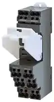


PTF-08-PU
Relay Socket, DIN Rail, Screw, 8 Pins, 10 A, 250 V, PTF Series
- Manufacturer: OMRON INDUSTRIAL AUTOMATION
- Product type: Relay Sockets
- SVHC: To Be Advised
- No. of Pins: 8Pins
- Product Range: PTF Series
- Current Rating: 10A
- Voltage Rating: 250V
- Socket Mounting: DIN Rail
- Socket Terminals: Screw
| Delivery and price | |
|---|---|
| Units per pack | 50 |
| Price | 10.08 € |
| Current stock | 10+ |
| Lead time | 30 days |
**General-purpose Relays MK-S** ## **Super MK Relays. Models with Latching Lever Added to the Series.** - Same mounting and internal wiring as the previous Super MK Relays - Built-in mechanical indicator enables checking contact operation. - Two modes can be used to check circuits for models with latching lever. - Nameplate provided on models with latching lever. - All materials are RoHS compliant. - UL and IEC (TÜV) certification. ## **Features** ## **Models with Latching Lever** Operation indicator * Nameplate Mechanical indicator Latching lever DC: Blue AC: Red ~~a~~ * The operation indicator is built in only on specified models. ## **Example of Applications of Models with Latching Levers** Operation checks in relay sequence circuits ## **Model Number Structure** **==> picture [246 x 267] intentionally omitted <==** **----- Start of picture text -----**<br> Operating Method for Latching Lever<br>Relay in For Momentary For Lock<br>Normal Operation Operation Operation<br>CO OD<br>Yellow<br>button<br>Slide the latching lever Slide the latching<br>to the first position, lever to the second<br>then press the yellow position.<br>button with an (The contact is now in<br>insulated tool to the locked position.)<br>operate the contact.<br>**----- End of picture text -----**<br> ## **Model Number Legend** ## **MKS** @@@@@ **-** @ **-** @ **1 2 3 4 5 6 7** ## **1. Contact Form** - 2: DPDT - 3: 3PDT ## **2. Terminals** P: Plug-in ## **3. Mechanical Indicator/Test Button** Blank: Mechanical indicator I: Mechanical indicator and lockable test button ## **4. LED Indicator** Blank: Standard N: LED indicator ## **5. Coil Polarity** Blank: Standard - 1: Reverse polarity (DC coil only) ## **6. Surge Absorption** Blank: Standard D: Surge absorber diode (DC coil only) V: Surge absorber varistor (AC coil only) ## **7. Internal Connections** Blank: Standard - 2 or 5: Non-standard connections (Refer to _“Terminal Arrangement and Internal Connection (Bottom View)”_ .) ## **8. Rated Voltage** (Refer to _“Coil Ratings”_ .) **1** **MK-S** ## **Ordering Information** ## **List of Models** |**Type**|**Terminals**|**Contact**<br>**form**|**Internal connections**<br>**(See note 3.)**|**With mechanical indicator**|**With mechanical indicator**<br>**and lockable test button**|**Coil ratings**| |---|---|---|---|---|---|---| |**Standard**<br>**Models**|Plug-in|DPDT|Standard|MKS2P|MKS2PI|AC/DC| ||||Non-standard|MKS2P-2|MKS2PI-2|| |||3PDT|Standard|MKS3P|MKS3PI|| ||||Non-Standard|MKS3P-2|MKS3PI-2|| |||||MKS3P-5|MKS3PI-5|| |**Models with**<br>**LED Indicator**<br>**(See note 2.)**||DPDT|Standard|MKS2PN(1)|MKS2PIN(1)|AC/DC| ||||Non-standard|MKS2PN(1)-2|MKS2PIN(1)-2|| |||3PDT|Standard|MKS3PN(1)|MKS3PIN(1)|| ||||Non-Standard|MKS3PN(1)-2|MKS3PIN(1)-2|| |||||MKS3PN(1)-5|MKS3PIN(1)-5|| |**Models with**<br>**Diode**<br>**(See note 2.)**||DPDT|Standard|MKS2P(1)-D|MKS2PI(1)-D|DC| ||||Non-standard|MKS2P(1)-D-2|MKS2PI(1)-D-2|| |||3PDT|Standard|MKS3P(1)-D|MKS3PI(1)-D|| ||||Non-Standard|MKS3P(1)-D-2|MKS3PI(1)-D-2|| |||||MKS3P(1)-D-5|MKS3PI(1)-D-5|| |**Models with**<br>**LED Indicator**<br>**and Diode**||DPDT|Standard|MKS2PN-D|MKS2PIN-D|DC| ||||Non-standard|MKS2PN-D-2|MKS2PIN-D-2|| |||3PDT|Standard|MKS3PN-D|MKS3PIN-D|| ||||Non-Standard|MKS3PN-D-2|MKS3PIN-D-2|| |||||MKS3PN-D-5|MKS3PIN-D-5|| |**Models with**<br>**Varistor**||DPDT|Standard|MKS2P-V|MKS2PI-V|AC| ||||Non-standard|MKS2P-V-2|MKS2PI-V-2|| |||3PDT|Standard|MKS3P-V|MKS3PI-V|| ||||Non-Standard|MKS3P-V-2|MKS3PI-V-2|| |||||MKS3P-V-5|MKS3PI-V-5|| |**Models with**<br>**LED Indicator**<br>**and Varistor**||DPDT|Standard|MKS2PN-V|MKS2PIN-V|AC| ||||Non-standard|MKS2PN-V-2|MKS2PIN-V-2|| |||3PDT|Standard|MKS3PN-V|MKS3PIN-V|| ||||Non-Standard|MKS3PN-V-2|MKS3PIN-V-2|| |||||MKS3PN-V-5|MKS3PIN-V-5|| **Note: 1.** When ordering, add the rated voltage to the model number. Rated voltages are given in the coil ratings table in the specifications. Example: MKS3P 24 VDC Rated voltage **2.** The DC coil comes in two types: standard coil polarity and reverse coil polarity. Refer to _Terminal Arrangement and Internal Connections (Bottom View)_ . Example: MKS2PIN1-2 24 VDC Reverse coil polarity **3.** Refer to _Terminal Arrangement and Internal Connections (Bottom View)_ for non-standard internal _connections_ . ## **List of Models (Order Separately)** |**Item**|**Type**|**Model**| |---|---|---| |Track-mounted<br>Socket|8-pin|PF083A-E| ||11-pin|PF113A-E| ||8-pin|PF083A-D| ||11-pin|PF113A-D| |Hold-down Clip<br>(For PF083A-E and PF113A-E)||PFC-A1| **2** **MK-S** ## **Specifications** ## **Ratings** ## **Coil Ratings** |**Rated**|**voltage**|**Rated current**|**Rated current**|**Coil resistance**|**Must operate**<br>**voltage**|**Must release**<br>**voltage**|**Max. voltage**|**Power**<br>**consumption**| |---|---|---|---|---|---|---|---|---| |||**50 Hz**|**60 Hz**||**Percentage of rated voltage**|||| |AC|6 V|443 mA|385 mA|3.1|80% max. of<br>rated voltage|30% min. of rated<br>voltage at 60 Hz<br>25% min. of rated<br>voltage at 50 Hz|110% of rated<br>voltage|Approx. 2.3 VA<br>at 60 Hz<br>Approx. 2.7 VA<br>at 50 Hz| ||12 V|221 mA|193 mA|13.7||||| ||24 V|110 mA|96.3 mA|48.4||||| ||100 V|26.6 mA|23.1 mA|760||||| ||110 V|24.2 mA|21.0 mA|932||||| ||200 V|13.3 mA|11.6 mA|3,160||||| ||220 V|12.1 mA|10.5 mA|3,550||||| ||230 V|10.0 mA|11.5 mA|4,250||||| ||240 V|11.0 mA|9.6 mA|4,480||||| |DC|6 V|224 mA||26.7||15% min. of rated<br>voltage||Approx. 1.4 W| ||12 V|112 mA||107||||| ||24 V|55.8 mA||430||||| ||48 V|28.1 mA||1,710||||| ||100 V|13.5 mA||7,390||||| ||110 V|12.3 mA||8,960||||| - **Note: 1.** The rated current and coil resistance are measured at a coil temperature of 23C with tolerances of +15%/20% for AC rated current and 15% for DC coil resistance. **2.** Performance characteristic data are measured at a coil temperature of 23C. **3.** The maximum voltage is one that is applicable instantaneously to the Relay coil at 23C and not continuously. **4.** For DC-operated Relays with the LED indicator built-in, add an LED current of approx. 5 mA to the rated current. ## **Contact Ratings** |**Contact Ratings**|||| |---|---|---|---| |**Load**||Resistive load<br>(cos= 1)|Inductive load<br>(cos= 0.4)| |**Contact mechanism**||Single|| |**Contact material**||AgSnIn|| |**Rated load**|**NO**|10 A, 250 VAC<br>10A, 30 VDC|7 A, 250 VAC| ||**NC**|5 A, 250 VAC<br>5 A, 30 VDC|| |**Rated carry current**||10 A|| |**Max. switching voltage**||250 VAC, 250 VDC|| |**Max. switching current**||10 A|| |**Max. switching power**|**NO**|2,500 VA/300 W|| ||**NC**|1,250 VA/150 W|| **3** **MK-S** ## **Characteristics** |**Characteristics**|| |---|---| |**Contact resistance**|100 mmax.| |**Operate time**|AC: 20 ms max.<br>DC: 30 ms max.| |**Release time**|20 ms max. (40 ms max. for built-in Diode Relays)| |**Max. operating frequency**|Mechanical: 18,000 operations/h<br>Electrical:<br>1,800 operations/h (under rated load)| |**Insulation resistance**|100 Mmin. (at 500 VDC)| |**Dielectric strength**|2,500 VAC 50/60 Hz for 1 min between coil and contacts<br>1,000 VAC 50/60 Hz for 1 min between contacts of same polarity and terminals of the same polarity<br>2,500 VAC 50/60 Hz for 1 min between current-carrying parts, non-current-carrying parts, and opposite polarity| |**Insulation method**|Basic insulation| |**Impulse withstand voltage**|4.5 kV between coil and contacts (with 1.250s impulse wave)<br>3.0 kV between contacts of differentpolarity(with 1.250s impulse wave)| |**Pollution degree**|3| |**Rated insulation voltage**|250 V| |**Vibration resistance**|Destruction: 10 to 55 to 10 Hz, 0.75-mm single amplitude (1.5-mm double amplitude)<br>Malfunction: 10 to 55 to 10 Hz, 0.5-mm single amplitude (1.0-mm double amplitude)| |**Shock resistance**|Destruction: 1,000 m/s2(approx. 100 G)<br>Malfunction: 100 m/s2(approx. 10 G)| |**Endurance**|Mechanical: 5,000,000 operations min. (at 18,000 operations/h under rated load)<br>Electrical:<br>100,000 operations h. (at 1,800 operations/h under rated load)| |**Failure rate P level (reference value)**|10 mA at 1 VDC| |**Ambient temperature**|Operating: –40 to 60C (with no icingor condensation)| |**Ambient humidity**|Operating: 5% to 85%| |**Weight**|Approx. 90g| - **Note: 1.** The values given above are initial values. **2.** P level: 60 = 0.1 10[-6] /operation **3.** Ambient temperature of models with LED indicator is 25 to 60C. ## **Approved Standards UL508 (File No. E41515)** |**Coil ratings**|**Contact ratings**|**Contact ratings**|**Operations**| |---|---|---|---| |6 to 110 VDC<br>6 to 240 VAC|N.O.<br>contact|10 A, 250 V AC 50/60 Hz (Resistive)<br>10 A, 30 V DC (Resistive)<br>7 A, 250 V AC 50/60 Hz (General Use)|100,000| ||N.C.<br>contact|10 A, 250 V AC 50/60 Hz (Resistive)<br>10 A, 30 V DC (Resistive)<br>7 A, 250 V AC 50/60 Hz (General Use)|100,000| **CSA Standard: CSA Certification by : CSA C22.2 No. 14** **IEC Standard/TUV Certification: IEC61810-1 (Certification No. R50104853)** |**Coil ratings**|**Contact ratings**|**Contact ratings**|**Operations**| |---|---|---|---| |6, 12, 24, 48,<br>100, 110 VDC<br>6, 12, 24, 100,<br>110, 200, 220,<br>240 VAC|N.O.<br>contact|10 A, 250 V AC 50/60 Hz (Resistive)<br>10 A, 30 V DC (Resistive)<br>7 A, 250 V AC 50/60 Hz (General Use)|100,000| ||N.C.<br>contact|5 A, 250 V AC 50/60 Hz (Resistive)<br>5 A, 30 V DC (Resistive)<br>7 A, 250 V AC 50/60 Hz (General Use)|100,000| **Note:** When Relays are mounted on the PF083A-E or PF113A-E, the maximum carrying current is 9 A. ## **Engineering Data** ## **Reference Data** **Maximum Switching Power** ## **Rated Carry Current vs. Ambient Rated Temperature** **==> picture [318 x 149] intentionally omitted <==** **----- Start of picture text -----**<br> 100<br>50 10<br>30<br>DC resistive load UL derating curve<br>with NO contact AC resistive load<br>with NO contact<br>10<br>5<br>5 AC inductive<br>load<br>3 (cos φ = 0.4)<br>DC resistive AC resistive load<br>load with with NC contact<br>NC contact<br>0<br>110 30 50 100 300 500 1.000 − 40 − 20 0 20 40 60 80<br>Switching voltage (V) Ambient temperature ( ° C)<br>Switching current (A) Rated carry current (A)<br>**----- End of picture text -----**<br> **Note:** The lower limit of the ambient operating temperature for models with built-in operation indicators is 25C. **4** **MK-S** **(Unit: mm)** ## **Dimensions** ## **Models without Latching Lever** ## **Models with Latching Lever** **==> picture [440 x 77] intentionally omitted <==** **----- Start of picture text -----**<br> 34.5 max. ir. | Ee. 34.5 max. Wir lal |<br>= 5<br>ile<br>i J } | = iar<br>a 34.5 max. 0.8 52.5 max. 7== 34.5 max. 0.8 LH 52.5 max.<br>**----- End of picture text -----**<br> ## **Sockets** See below for Socket dimensions. **==> picture [505 x 351] intentionally omitted <==** **----- Start of picture text -----**<br> Surface-mounting Socket (for track or screw mounting)<br>Socket<br>Finger-protection models ---<br>_<br>Maximum carry 10 A 5 A<br>current<br>PF083A-E PF083A-D PF083A<br>2 poles<br>PF113A-E PF113A-D PF113A<br>3 poles<br>a<br>Note: Use the Surface-mounting Sockets (i.e., finger-protection models) with “-E” at the end of the model number. When using the PF083A and<br>PF113A, be sure not to exceed the Socket's maximum carry current of 5 A. Using at a current exceeding 5 A may lead to burning. Round<br>terminals cannot be used for finger-protection models. Use Y-shaped terminals.<br>PF083A-E (Conforming to EN 50022) PF113A-E (Conforming to EN 50022)<br>Eight, M3.5 × 7 sems Terminal Arrangement Terminal Arrangement<br>7 4 Eleven, M3.5 × 7 sems<br>7 4<br>| Sia =, [rere 4} ene<br>52 max. x ye 35.4 Vey ia EEE oan)<br>52 max. 35.4<br>ied 33 3.5 of 2 [S| Eee 7 Fea<br>me) 41 max. eee in 0000,<br>21 max. Mounting Holes 4 34 3.5 2 Mounting Holes<br>Two, M4 or two 4.5-dia. holes to ae 42.8 max. ae 31 max. Two, M4 or two 4.5-dia. holes fy<br>33 ± 0.2 es 33 ± 0.2<br>**----- End of picture text -----**<br> **Note:** Use the Surface-mounting Sockets (i.e., finger-protection models) with “-E” at the end of the model number. When using the PF083A and PF113A, be sure not to exceed the Socket's maximum carry current of 5 A. Using at a current exceeding 5 A may lead to burning. Round terminals cannot be used for finger-protection models. Use Y-shaped terminals. ## **PF083A-E (Conforming to EN 50022)** **5** **MK-S** **==> picture [36 x 6] intentionally omitted <==** **----- Start of picture text -----**<br> PF113A-D<br>**----- End of picture text -----**<br> **==> picture [507 x 189] intentionally omitted <==** **----- Start of picture text -----**<br> PF083A-D PF113A-D<br>8 Terminal Arrangement<br>24 22 12 14 8 Terminal Arrangement<br>5.5 6 5 4 3 32 24 21 22 12<br>5.5 8 7 6 5 4<br>4 27 27<br>4<br>Eight, M4 screws<br>7 8 1 2 Eight, M4 screws<br>A2 <a 21 11 A1 lo 349 Posey A210 11 1 A12 143<br>O O 31 11<br>65 Mounting Holes 65<br>Two, M4 or two 4.5-dia. hole Mounting Holes<br>Two, M4 or two 4.5-dia. hole<br>30<br>30<br>2° 0 38 0% rf weer 38 ‘et<br>**----- End of picture text -----**<br> ## **Hold-down Clips** **==> picture [103 x 101] intentionally omitted <==** **----- Start of picture text -----**<br> PFC-A1<br>(2 pieces per set)<br>4.6<br>60.8<br>62<br>ut 6 4.5<br>**----- End of picture text -----**<br> ## **Mounting Tracks** **PFP-100N, PFP-50N (Conforming to EN 50022)** **PFP-100N2 (Conforming to EN 50022)** **==> picture [470 x 73] intentionally omitted <==** **----- Start of picture text -----**<br> 16<br>7.3 ± 0.15<br>4.5<br>4.5<br>35 ± 0.3 27 ± 0.15 35 ± 0.3 27 24 29.2<br>15 25 10 25 1000 (500)* 25 10 25 * 1 15 25 10 25 1000 ± 4 25 10 25 15 1 1.5<br>* This dimension applies to the PFP-50N Mounting Track. * A total of twelve 25 × 4.5 elliptic holes is provided with six<br>**----- End of picture text -----**<br> * A total of twelve 25 × 4.5 elliptic holes is provided with six holes cut from each track end at a pitch of 10 mm. ## **Mounting Height with Sockets** ## **Surface-mounting Sockets** **==> picture [258 x 93] intentionally omitted <==** **----- Start of picture text -----**<br> Three<br>poles<br>77.8 Two 87.8<br>(See poles (See 84.3<br>note.) 74.3 note.)<br>aul<br>PF083A(-E) PF113A(-E)<br>Note: PF083A(-E) and PF113A(-E) allow either track or screw mounting.<br>**----- End of picture text -----**<br> **6** **MK-S** ## **Terminal Arrangement and Internal Connection (Bottom View)** |**Standard Models**<br>**(AC/DC Coil)**<br>**Models with**<br>**LED Indicator**<br>**(AC Coil)**<br>**Models with Diode**<br>**(DC Coil:**<br>**Standard Polarity)**<br>**Models with**<br>**LED Indicator and Diode**<br>**(DC Coil:**<br>**Reverse Polarity)**<br>**Standard Models**<br>**(DC Coil:**<br>**Standard Polarity)**<br>**Models with Diode**<br>**(DC Coil:**<br>**Reverse Polarity)**<br>**Models with**<br>**LED indicator**<br>**(DC Coil)**|**MK**|**S2P(I)**|**MKS2P(I)-2**|**MKS2P(I)-2**|**MKS2P(I)-2**||**MKS3P(I)**|**MKS3P(I)**||**MKS3P(I)-2**|**MKS3P(I)-2**|**MKS3P(I)-2**|**MKS3P(I)-5**|**MKS3P(I)-5**| |---|---|---|---|---|---|---|---|---|---|---|---|---|---|---| ||1<br>2<br>3<br>4|5<br>6<br>7<br>8|3<br>2|8<br>6<br><br>1<br><br>7<br>4<br>5|||1<br>2<br>3<br>4<br>5<br>6<br>7<br>8<br>10<br>11<br>9|||||9<br>11<br>10<br>8<br>7<br>6|5<br>4<br>3<br>2<br>1|9<br>11<br>10<br>8<br>7<br>6| |||||||||||5<br>4<br>3<br>2<br>1||||| ||**MKS**|**2P(I)N**|**MKS2P(I)N-2**||||**MKS3P(I)N**|||**MKS3P(I)N-2**|||**MKS3P(I)N-5**|| ||4<br>3<br>2<br>1|8<br>7<br>6<br>5|2<br>3|5<br>4<br>7<br><br>1<br><br>6<br>8||||6<br>7<br>8<br>10<br>11<br>9||||9<br>11<br>10<br>8<br>7<br>6|5<br>4<br>3<br>2<br>1|9<br>11<br>10<br>8<br>7<br>6| ||||||||1<br>2<br>3<br>4<br>5|||5<br>4<br>3<br>2<br>1||||| ||**MKS**|**2P(I)N**|**MKS2P(I)N-2**||||**MKS3P(I)N**|||**MKS3P(I)N-2**|||**MKS3P(I)N-5**|| ||4<br>3<br>2<br>1|8<br>7<br>6<br>5|2<br>3|4<br><br>1<br>|5<br>7<br>6<br>8|||6<br>7<br>8<br>10<br>11<br>9||||9<br>11<br>10<br>8<br>7<br>6|5<br>4<br>3<br>2<br>1|9<br>11<br>10<br>8<br>7<br>6| ||||||||1<br>2<br>3<br>4<br>5|||4<br>3<br>|5<br>|||| ||||||||||||2<br>1|||| |||||||||||||||| |||||||||||||||| |||||||||||||||| |||||||||||||||| ||**MKS2P(I)N1**||**MKS2P(I)N1-2**||||**MKS3P(I)N1**|||**MKS3P(I)N1-2**|||**MKS3P(I)N1-5**|| ||4<br>3<br>2<br>1|8<br>7<br>6<br>5|2<br>3|5<br>4<br>7<br><br>1<br><br>6<br>8||||6<br>7<br>8<br>10<br>11<br>9||||9<br>11<br>10<br>8<br>7<br>6|5<br>4<br>3<br>2<br>1|9<br>11<br>10<br>8<br>7<br>6| ||||||||1<br>2<br>3<br>4<br>5|||4<br>3<br>|5<br>|||| ||||||||||||2<br>1|||| |||||||||||||||| |||||||||||||||| |||||||||||||||| ||**MKS2P(I)-D**||**MKS2P(I)-D-2**||||**MKS3P(I)-D**|||**MKS3P(I)-D-2**|||**MKS3P(I)-D-5**|| ||4<br>3<br>2<br>1|8<br>7<br>6<br>5|2<br>3|4<br><br>1<br>|5<br>7<br>6<br>8|||6<br>7<br>8<br>10<br>11<br>9||||9<br>11<br>10<br>8<br>7<br>6|5<br>4<br>3<br>2<br>1|9<br>11<br>10<br>8<br>7<br>6| ||||||||1<br>2<br>3<br>4<br>5|||5<br>4<br>3<br>2<br>1||||| |||||||||||||||| |||||||||||||||| ||**MKS2P(I)1-D**||**MKS2P(I)1-D-2**||||**MKS3P(I)1-D**|||**MKS3P(I)1-D-2**|||**MKS3P(I)1-D-5**|| ||4<br>3<br>2<br>1|8<br>7<br>6<br>5|2<br>3|5<br>4<br>7<br><br>1<br><br>6<br>8||||6<br>7<br>8<br>10<br>11<br>9||||9<br>11<br>10<br>8<br>7<br>6|5<br>4<br>3<br>2<br>1|9<br>11<br>10<br>8<br>7<br>6| ||||||||1<br>2<br>3<br>4<br>5|||4<br>3<br>|5<br>|||| ||||||||||||2<br>1|||| |||||||||||||||| |||||||||||||||| |||||||||||||||| ||**MKS2P(I)N-D**||**MKS2P(I)N-D-2**||||**MKS3P(I)N-D**|||**MKS3P(I)N-D-2**|||**MKS3P(I)N-D-5**|| ||1<br>2<br>3<br>4|5<br>6<br>7<br>8|3<br>2|1<br><br>4|8<br>6<br>7<br>5|||6<br>7<br>8<br>10<br>11<br>9||||9<br>11<br>10<br>8<br>7<br>6|5<br>4<br>3<br>2<br>1|9<br>11<br>10<br>8<br>7<br>6| ||||||||1<br>2<br>3<br>4<br>5|||4<br>3<br>|5<br>|||| ||||||||||||2<br>1|||| |||||||||||||||| |||||||||||||||| |||||||||||||||| |||||||||||||||| **7** **MK-S** |**Models with Varistor**<br>**(AC Coil)**<br>**Models with**<br>**LED indicator and**<br>**Varistor**<br>**(AC Coil)**|**MKS2P(I)-V**|**MKS2P(I)-V**|**MKS2P(I)-V**|**MKS2P(I)-V**|**MKS2P(I)-V-2**|**MKS2P(I)-V-2**|**MKS2P(I)-V-2**||**MKS3P(I)-V**|**MKS3P(I)-V**|**MKS3P(I)-V**||**MKS3P(I)-V-2**|**MKS3P(I)-V-2**|**MKS3P(I)-V-2**|**MKS3P(I)-V-5**|**MKS3P(I)-V-5**| |---|---|---|---|---|---|---|---|---|---|---|---|---|---|---|---|---|---| |||4<br>3||8<br>7<br>6<br>5|2<br>3|5<br>4<br>7<br><br>1<br><br>6<br>8|||||6<br>7<br>8<br>10<br>11<br>9||||9<br>11<br>10<br>8<br>7<br>6|9<br>11<br>10<br>8<br>7<br>6<br>5<br>4<br>3<br>2<br>1|| ||||||||||2<br>3<br>4|1<br><br><br>5|||5<br>4<br>3<br>2<br>1||||| |||2<br>1|||||||||||||||| ||||||||||||||||||| ||||||||||||||||||| ||||||||||||||||||| ||**MKS2P(I)N-V**||||**MKS2P(I)N-V-2**||||**MKS3P(I)N-V**||||**MKS3P(I)N-V-2**|||**MKS3P(I)N-V-5**|| |||3|4|5<br>6<br>7<br>8|3<br>2|1<br><br>4|8<br>6<br>7<br>5||||9<br>11<br>10<br>8<br>7<br>6||||6<br>7<br>8<br>10<br>11<br>9|2<br>3<br>4|1<br>5<br>6<br>7<br>8<br>10<br>11<br>9| ||||||||||4<br>3<br>2|5<br><br><br>1|||2<br>3<br>4|5<br>|||| |||2|1|||||||||||1<br>|||| ||||||||||||||||||| ||||||||||||||||||| **8** **MK-S** ## **Safety Precautions** ## **Safety Precautions for Correct Use** ## **Installation** Mount the MK-S with the marking at the bottom. ## **Handling** Check the coil polarity of models with built-in diodes and wire them correctly (DC operation coil). ## **Test Button** Do not use the test button for any purpose other than testing. Be sure not to touch the test button accidentally as this will turn the contacts ON. Before using the test button, confirm that circuits, the load, and any other connected item will operate safely. Check that the test button is released before turning ON relay circuits. If the test button is pulled out too forcefully, it may bypass the momentary testing position and go straight into the locked position. Use an insulated tool when you operate the test button. Models with test buttons or LED indicators fulfill the requirements for reinforced insulation between live parts and the front of cover only when the Relay is in a complete condition, i.e. with the nameplate, nameplate frame, test button, and slider in place. If any of these parts are removed, only the requirements for basic insulation are fulfilled. **9** **MK-S** **10** ## **READ AND UNDERSTAND THIS DOCUMENT** Please read and understand this document before using the products. Please consult your OMRON representative if you have any questions or comments. ## **WARRANTY** OMRON’s exclusive warranty is that the products are free from defects in materials and workmanship for a period of one year (or other period if specified) from date of sale by OMRON. OMRON MAKES NO WARRANTY OR REPRESENTATION, EXPRESS OR IMPLIED, REGARDING NON-INFRINGEMENT, MERCHANTABILITY, OR FITNESS FOR PARTICULAR PURPOSE OF THE PRODUCTS. ANY BUYER OR USER ACKNOWLEDGES THAT THE BUYER OR USER ALONE HAS DETERMINED THAT THE PRODUCTS WILL SUITABLY MEET THE REQUIREMENTS OF THEIR INTENDED USE. OMRON DISCLAIMS ALL OTHER WARRANTIES, EXPRESS OR IMPLIED. ## **LIMITATIONS OF LIABILITY** OMRON SHALL NOT BE RESPONSIBLE FOR SPECIAL, INDIRECT, OR CONSEQUENTIAL DAMAGES, LOSS OF PROFITS OR COMMERCIAL LOSS IN ANY WAY CONNECTED WITH THE PRODUCTS, WHETHER SUCH CLAIM IS BASED ON CONTRACT, WARRANTY, NEGLIGENCE, OR STRICT LIABILITY. In no event shall responsibility of OMRON for any act exceed the individual price of the product on which liability is asserted. IN NO EVENT SHALL OMRON BE RESPONSIBLE FOR WARRANTY, REPAIR, OR OTHER CLAIMS REGARDING THE PRODUCTS UNLESS OMRON’S ANALYSIS CONFIRMS THAT THE PRODUCTS WERE PROPERLY HANDLED, STORED, INSTALLED, AND MAINTAINED AND NOT SUBJECT TO CONTAMINATION, ABUSE, MISUSE, OR INAPPROPRIATE MODIFICATION OR REPAIR. ## **SUITABILITY FOR USE** THE PRODUCTS CONTAINED IN THIS DOCUMENT ARE NOT SAFETY RATED. THEY ARE NOT DESIGNED OR RATED FOR ENSURING SAFETY OF PERSONS, AND SHOULD NOT BE RELIED UPON AS A SAFETY COMPONENT OR PROTECTIVE DEVICE FOR SUCH PURPOSES. Please refer to separate catalogs for OMRON's safety rated products. OMRON shall not be responsible for conformity with any standards, codes, or regulations that apply to the combination of products in the customer’s application or use of the product. At the customer’s request, OMRON will provide applicable third party certification documents identifying ratings and limitations of use that apply to the products. This information by itself is not sufficient for a complete determination of the suitability of the products in combination with the end product, machine, system, or other application or use. The following are some examples of applications for which particular attention must be given. This is not intended to be an exhaustive list of all possible uses of the products, nor is it intended to imply that the uses listed may be suitable for the products: - Outdoor use, uses involving potential chemical contamination or electrical interference, or conditions or uses not described in this document. - Nuclear energy control systems, combustion systems, railroad systems, aviation systems, medical equipment, amusement machines, vehicles, safety equipment, and installations subject to separate industry or government regulations. - Systems, machines, and equipment that could present a risk to life or property. Please know and observe all prohibitions of use applicable to the products. NEVER USE THE PRODUCTS FOR AN APPLICATION INVOLVING SERIOUS RISK TO LIFE OR PROPERTY WITHOUT ENSURING THAT THE SYSTEM AS A WHOLE HAS BEEN DESIGNED TO ADDRESS THE RISKS, AND THAT THE OMRON PRODUCT IS PROPERLY RATED AND INSTALLED FOR THE INTENDED USE WITHIN THE OVERALL EQUIPMENT OR SYSTEM. ## **PERFORMANCE DATA** Performance data given in this document is provided as a guide for the user in determining suitability and does not constitute a warranty. It may represent the result of OMRON’s test conditions, and the users must correlate it to actual application requirements. Actual performance is subject to the OMRON Warranty and Limitations of Liability. ## **CHANGE IN SPECIFICATIONS** Product specifications and accessories may be changed at any time based on improvements and other reasons. It is our practice to change model numbers when published ratings or features are changed, or when significant construction changes are made. However, some specifications of the product may be changed without any notice. When in doubt, special model numbers may be assigned to fix or establish key specifications for your application on your request. Please consult with your OMRON representative at any time to confirm actual specifications of purchased products. ## **DIMENSIONS AND WEIGHTS** Dimensions and weights are nominal and are not to be used for manufacturing purposes, even when tolerances are shown. ## **ERRORS AND OMISSIONS** The information in this document has been carefully checked and is believed to be accurate; however, no responsibility is assumed for clerical, typographical, or proofreading errors, or omissions. ## **PROGRAMMABLE PRODUCTS** OMRON shall not be responsible for the user’s programming of a programmable product, or any consequence thereof. ## **COPYRIGHT AND COPY PERMISSION** This document shall not be copied for sales or promotions without permission. This document is protected by copyright and is intended solely for use in conjunction with the product. Please notify us before copying or reproducing this document in any manner, for any other purpose. If copying or transmitting this document to another, please copy or transmit it in its entirety. **MK-S** Cat. No. J168-E2-02A-X **In the interest of product improvement, specifications are subject to change without notice.** ## **OMRON EUROPE B.V.** Wegalaan 67-69, NL-2132 JD, Hoofddorp, The Netherlands Phone: +31 23 568 13 00 Fax: +31 23 568 13 88 industrial.omron.eu **12**
Updated at June 6, 2026
With a legacy spanning over 80 years, Omron Industrial Automation is a globally recognized leader in the manufacture of advanced industrial control and automation components. Renowned for their reliability and engineering excellence, Omron delivers comprehensive solutions that enhance efficiency, machine safety, and precision across a wide range of manufacturing environments. Our extensive portfolio of Omron products is heavily focused on their industry-leading sensing and switching technologies. We offer a vast selection of sensors, excelling specifically in high-performance proximity sensors, light sensors, and temperature sensors. Complementing this range are robust switching solutions, featuring a deep inventory of power relays, solid-state relays, safety relays, and essential relay accessories designed for demanding operational requirements. Beyond sensing and switching, Omron is highly regarded for its precision automation and process control equipment. Our selection features highly accurate temperature controllers, versatile process controllers, and sophisticated panel displays and instrumentation. To support these fundamental systems, we also supply dependable Omron power supplies, notably AC/DC converters, alongside vital connectivity components like DIN rail terminal blocks to ensure secure, efficient, and complete industrial setups.
About Novapart
Novapart is a B2B electronic component broker specialising in stock shortages and cost reduction. We source hard-to-find parts and identify compliant alternatives across a catalogue of 410,000+ components from 500+ manufacturers.
Learn more →Stock Shortage Specialist
When a component is unavailable, discontinued or has an unacceptable lead time, we tap into our network of vetted European and Asian distributors to source what you need — without compromising on quality or traceability.
Request a quote →Compliant Alternatives
We identify pin-to-pin, electrically equivalent substitutes that meet the same certifications (RoHS, AEC-Q100, REACH) as your original specification — validated against datasheets, not just part numbers. Often at a lower cost.
BOM Analysis service →