
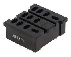


PT11-0
Relay Socket, Through Hole, PC Pin, 11 Pins, 10 A, 250 V
- Manufacturer: OMRON INDUSTRIAL AUTOMATION
- Product type: Relay Sockets
- SVHC: To Be Advised
- No. of Pins: 11Pins
- Product Range: -
- Current Rating: 10A
- Voltage Rating: 250V
- Socket Mounting: Through Hole
- Socket Terminals: PC Pin
| Delivery and price | |
|---|---|
| Units per pack | 50 |
| Price | 2.51 € |
| Current stock | 10+ |
| Lead time | 30 days |
CSM_common_sockets_DS_E_5_12

## **Common Sockets**

## **A Wide Variety of Square and Round Sockets in Front-mounting and Back-mounting Models**

- Models available with finger protection.

- Hold-down Clips and Short Bars for PYFZ/PYF Sockets are also available.

- New screwless models available.

For the most recent information on models that have been certified for safety standards, refer to your OMRON website.

## **Ordering Information**

## **Square Sockets**

**==> picture [502 x 339] intentionally omitted <==**

**----- Start of picture text -----**<br>
Model<br>P2RF (front-mounting), page 9<br>Number<br>of pins<br>P2RFZ-05 P2RF-05 P2RFZ-05-E [*1]<br>Approx. 30 g Approx. 27 g Approx. 30 g<br>5 pins<br>P2RFZ-08  P2RF-08  P2RFZ-08-E [*1]<br>Approx. 38 g  Approx. 33 g I  Approx. 38 g<br>8 pins<br>NEW ei , NEW<br>Model P2R (back-mounting), pages 13 and 14<br>P7TF (front-mounting), page 14<br>Number<br>Solder terminals PCB terminals<br>of pins<br> P2R-05A [*2]  P2R-05P  P2R-057P  P7TF-05<br> Approx. 5 g  Approx. 5 g  Approx. 5.5 g  Approx. 28 g<br>5 pins<br> P2R-08A [*2]  P2R-08P  P2R-087P<br> Approx. 5 g  Approx. 5 g  Approx. 5.5 g<br>---<br>8 pins<br>**----- End of picture text -----**<br>


- **Note: 1.** The structure of @ -E models provides finger protection. Round terminals cannot be used. Use forked crimp terminals. **2.** To remove the Relay, pull the lever on the Socket with your fingers supporting the lever and the opposite side of the Relay case, and jiggle the Relay.

- *1. Use a #1 Phillips screwdriver to tighten the screws on this Socket.

- *2. This is not a flux-tight structure. We recommend manual soldering for this product.

**1**

**Common Sockets**

**==> picture [491 x 357] intentionally omitted <==**

**----- Start of picture text -----**<br>
Model PY (back-mounting), pages 18 to 14<br>PYF (front-mounting), page 15<br>Number<br>Solder terminals Wrapping terminals PCB terminals<br>of pins<br>ee es ee<br>PYFZ-08 PYFZ-08-E  [*3] PY08 PY08-Y1 PY08QN PY08QN-Y1 PY08-02 [*2]<br>Approx.  32 g Approx.  32 g Approx. 8 g PY08-Y3 Approx. 12 g PY08QN2-Y1 Approx. 7.2 g<br>PY08QN2<br>8 pins<br>PYF08M<br>Approx. 26 g<br>PYF11A PY11 PY11-Y1 PY11QN PY11QN-Y1 PY11-02 [*2]<br>Approx. 43 g Approx. 9 g PY11QN2 PY11QN2-Y1<br>11 pins<br>ll M<br>PYFZ-14 PYFZ-14-E  [*1] PY14 PY14-Y1 PY14QN PY14QN-Y1 PY14-02 [*2]<br>Approx. 50 g Approx. 50 g Approx. 10 g PY14-Y3 Approx. 14 g PY14QN2-Y1<br>PY14QN2 PY14QN-Y3<br>PY14QN2-Y3<br>14 pins<br>¥ | :<br>**----- End of picture text -----**<br>


- **Note:** The structure of @ -E models provides finger protection. Round terminals cannot be used. Use forked crimp terminals. *1. Use a #1 Phillips screwdriver to tighten the screws on this Socket.

- *2. The structure does not resist flux. Manual soldering is recommended for this product.

**2**

**Common Sockets**

**==> picture [493 x 287] intentionally omitted <==**

**----- Start of picture text -----**<br>
Model PT (back-mounting), pages 22 to 16<br>PTF (front-mounting), pages 20 to 15<br>Number<br>Solder terminals Wrapping terminals PCB terminals<br>of pins<br>PTF08A  Approx. 47 g PTFZ-08-E [*1] PT08  Approx. 11 g PT08QN PT08-0  [*2]<br>Approx. 46 g Approx. 10.4 g Approx. 8 g<br>rf NEW a ll |<br>8 pins<br>PTF08A-E  [*1]<br>Approx. 49 g<br>Fa g<br>PTF11A  Approx. 61 g PT11  Approx. 13 g PT11QN PT11-0  [*2]<br>Approx. 12.2 g<br>11 pins<br>ce = WW<br>yy = NM<br>PTF14A  Approx. 77 g PTFZ-14-E  [*1] PT14  Approx. 17 g PT14QN PT14-0  [*2]<br>Approx. 74 g Approx.  Approx. 16.2 g<br>rs ~ 20 g RES? |<br>“iy NEW bald | as<br>14 pins<br>PTF14A-E  [*1]<br>Approx. 79 g<br>**----- End of picture text -----**<br>


- **Note:** The structure of @ -E models provides finger protection. Round terminals cannot be used. Use forked crimp terminals. *1. Use a #1 Phillips screwdriver to tighten the screws on this Socket.

- *2. The structure does not resist flux. Manual soldering is recommended for this product.

**==> picture [143 x 70] intentionally omitted <==**

**----- Start of picture text -----**<br>
Model<br>Number  P7LF (front-mounting), page 23<br>of pins<br> P7LF-06  Approx. 60 g<br>y|7<br>6 pins<br>**----- End of picture text -----**<br>


**Note:** Refer to _Models with Standards Certification_ for detailed information on the models of Common Sockets that are certified for standards.

**3**

**Common Sockets**

## **Round Sockets**

**==> picture [512 x 440] intentionally omitted <==**

**----- Start of picture text -----**<br>
Model PL (back-mounting), page 28<br>PF (front-mounting),  P2CF (front-mounting),  PFA (front-mounting),  P3G (back-mounting),<br>Number  page 24 page 25 page 26 page 27 Solder  Wrapping  PCB<br>of pins terminals terminals terminals<br>PF083A P2CF-08 8PFA P3G-08 PL08 PL08-Q PLE08-0<br>Approx. 34 g Approx. 55 g Approx.  Approx. 40g Approx. 14 g Approx. 15 g Approx.<br>57 g 10.6g<br>PF083A-E  [*]<br>P2CF-08-E<br>8 pins 8PFA1 Note: The Y92A-48G<br>Approx.  Terminal Cover<br>66 g can be used to<br>PF085A provide finger<br>Approx. 40 g protection.<br>PF113A P2CF-11 11PFA P3GA-11 PL11 PL11-Q PLE11-0<br>Approx.  Approx.  Approx. 74 g Approx.  Approx. 15 g Approx.  Approx.<br>47 g 70g 47 g 18.5A 10.8 g<br>11 pins<br>PF113A-E  [*] P2CF-11-E Note: The Y92A-48G<br>Terminal Cover<br>can be used to<br>provide finger<br>protection.<br>14PFA  Approx. 104 g PL15<br>Approx. 28 g<br>--- --- --- --- ---<br>14 pins<br>PL20<br>Approx. 17 g<br>--- --- --- --- --- ---<br>20 pins<br>**----- End of picture text -----**<br>


**Note:** The structure of @ -E models provides finger protection. Round terminals cannot be used. Use forked crimp terminals. * Use a #1 Phillips screwdriver to tighten the screws on this Socket.

## **Terminal Cover**

|**Model**|**Y92A-48G**|
|---|---|
|**Appearance**||


**Note:** Refer to Models with Standards Certification for detailed information on the models of Common Sockets that are certified for standards.

**4**

**Common Sockets**

## **Hold-down Clips For Square Sockets**

## **(Unit: mm)**

**==> picture [511 x 356] intentionally omitted <==**

**----- Start of picture text -----**<br>
PKC  One Set (2 Clips) PTC-1 PYC-A1  Approx. 0.54 g  PYC-E1 PYC-P  Approx. 1.4 g PYC-P2  Approx. 1.2 g<br>4.5 5 One Set (2 Clips) One Set (2 Clips)<br>3<br>3.3 Approx. 5 Approx. 5 10<br>10 5<br>28<br>7° 29 29 max . Approx. 3<br>71.8 36.4 36.3<br>2.7 2.7 36.3 [40.7] 38.5<br>4.5<br>3 4.5 1 4.5 1.2 4.5 ±0.1 5.8 1.2 4.3<br>2.5 9.6<br>PYC-S  Approx. 1.8 g PYC-1  Approx. 6 g PYC-2 PYC-3 PYC-5 PYC  Approx. 0.2 g<br>8 9.4 8 5 10 10<br>28<br>28 28.8 Approx. 3 29.5 3.7<br>3.7<br>1.8<br>34.5<br>52 58.2 44.5 41.7<br>Y92H-1 Y92H-3 Y92H-4<br>One Set (2 Clips) One Set (2 Clips) R9<br>3.5<br>6 3 5<br>3.5 30.5<br>24.5 2.5<br>53<br>1.5 72.9 20 (84°)<br>1.5<br>34.7<br>23.5<br>6 33.7<br>6 10 2 4.5 1.2 4.5<br>**----- End of picture text -----**<br>


## **For Round Sockets**

**==> picture [511 x 257] intentionally omitted <==**

**----- Start of picture text -----**<br>
PFC-A1  Approx. 2.2 g  PFC-A6  Approx. 2.4 g PFC-A7  Approx. 3.0 g  PLC  Approx. 2.4 g PLC-1  Approx. 2.6 g  PLC-7  Approx. 3.0 g<br>One Set (2 Clips) One Set (2 Clips) One Set (2 Clips) One Set (2 Clips) One Set (2 Clips) One Set (2 Clips)<br>4.6 4.6<br>4.6<br>60.8 62 73.3 74.5 94 95.2 56.6 56.3 69.2 65.7<br>7.6 8 8<br>6 4.5<br>6 4.5 9<br>6 4.5<br>PLC-8  Approx. 6.4 g  PLC-10  Approx. 2.0 g PLC-12  Approx. 5.4 g<br>One Set (2 Clips) One Set (2 Clips) One Set (2 Clips)<br>5<br>90.2 86.7 64.3<br>66.2<br>8 8<br>9 6<br>**----- End of picture text -----**<br>


**5**

**Common Sockets**

## **Applicable Hold-down Clips**

## **For Square Sockets**

|**Sockets**|**PYF(Z) Series**|**PTF(Z) Series**|**PYF08M**|**PY**@**(QN)**|**PT**@**(QN)**|**PY**@**-02**|**PT**@**-0**|
|---|---|---|---|---|---|---|---|
|**Applicable models**||||||||
|**MY**@**, MY**@**N,**<br>**MY**@**-D,**<br>**MY2**@**-CR,**<br>**MY4**@**-CR,**<br>**MY4Z**@**-CR,**<br>**MY**@**-TU,**<br>**MY2K,**<br>**MY**@**N-D2,**<br>**MYQ**@**,**<br>**G3F(D) Series,**<br>**G3FM**|PYC-A1|---|PYC<br>PYC-P|PYC-P|---|PYC-P|---|
|**LY**@**, LY**@**N,**<br>**LY**@**-TU,**<br>**G3H(D) Series,**<br>**G9H**|---|PYC-A1|---|---|PYC-P|---|PYC-P|
|**MY**@**I ***|PYC-A1|---|---|PYC-P2|---|PYC-P2|---|
|**LY**@**I**|---|PYC-A1|---|---|PYC-P2|---|PYC-P2|
|**MY4H**|PYC-A1|---|---|PYC-P|---|PYC-P|---|
|**MY2Z**@**-CR,**<br>**MY3**@**-CR**|Y92H-3|---|---|PYC-1|---|PYC-1|---|
|**LY**@**-CR**|---|Y92H-3|---|---|PYC-1|---|---|
|**G7K**|---|PKC|---|---|---|---|---|
|**H3Y**|Y92H-3|---|Y92H-4||---|Y92H-4|---|


**Note:** The @ in the model number is replaced with 08, 11, or 14.

- If you use a Hold-down Clip with the MY2I, you cannot use the PYFZ-08. Use the PYFZ-14.

## **For Round Sockets**

|**Sockets**|**PF083A**<br>**PF113A**|**PL08 (-Q)**<br>**PL11 (-Q)**|**PLE08-0**<br>**PLE11-0**|**P2CF-11**|
|---|---|---|---|---|
|**Applicable models**|||||
|**61F-03B, -04B**|PFC-A1|PLC|PLC-10|---|
|**61F-GP-N,**<br>**-GPN-BT**<br>**61F-GP-N8**<br>**?61F-APN2**|PFC-N8|PHC-5|||
|**MK2P Series,**<br>**MK2KP,**<br>**MK3P**@**(-US), and**<br>**G3B(D) Series**|PFC-A1|PLC|||
|**MK3ZP**<br>**MK3LP**||PLC-1|||
|**MYA-NA1, -NB1**<br>**MYA-LA1, -LB1**<br>**MYA-NA2, -NB2**<br>**MYA-LA2, -LB2**|PFC-A6|PLC-7|---|---|
|**MYA-LA12, -LB12**|PFC-A7|PLC-8|---|---|
|**APR-S**|PFC-A6|PLC-7|---|---|
|**APR-S380/-S440**|---|---|---|Y92H-1|
|**LG2**|PFC-A7|PLC-8|---|---|
|**K6EL**|---|Y92H-1|---|---|


**Note: 1.** The 8PFA(1), 11PFA, and 14PFA are held with hooks.

**2.** The PL15, PL20, and PF202, as well as models not given in the above table, require panel processing for installation.

**3.** The PF085A Hold-down Clip is included with the H3M and H2A. It is an option (sold separately) for the H2C.

**6**

**Common Sockets**

## **Specifications**

## **Socket Characteristics**

|**Model**|**Continuous**<br>**carry current**|**Dielectric strength**|**Insulation**<br>**resistance*1**|**Remarks**|
|---|---|---|---|---|
|P2RFZ-05(-E)|10 A|Between contact terminals of same polarity: 1,000 VAC for 1 min|1,000 MΩmin.||
|||Between coil and contact terminals: 4,000 VAC for 1 min|||
|P2RFZ-08(-E)|6 A|Between contact terminals of different polarity: 3,000 VAC for 1 min|1,000 MΩmin.||
|||Between contact terminals of same polarity: 1,000 VAC for 1 min|||
|||Between coil and contact terminals: 4,000 VAC for 1 min|||
|P2RF-05(-E)|10 A|Between contact terminals of same polarity: 1,000 VAC for 1 min|1,000 MΩmin.||
|||Between coil and contact terminals: 4,000 VAC for 1 min|||
|P2RF-08(-E)|5 A|Between contact terminals of different polarity: 3,000 VAC for 1 min|1,000 MΩmin.||
|||Between contact terminals of same polarity: 1,000 VAC for 1 min|||
|||Between coil and contact terminals: 4,000 VAC for 1 min|||
|P2R-05P|10 A|Between contact terminals of same polarity: 1,000 VAC for 1 min|1,000 MΩmin.||
|||Between coil and contact terminals: 4,000 VAC for 1 min|||
|P2R-08P|5 A|Between contact terminals of different polarity: 3,000 VAC for 1 min|1,000 MΩmin.||
|||Between contact terminals of same polarity: 1,000 VAC for 1 min|||
|||Between coil and contact terminals: 4,000 VAC for 1 min|||
|P2R-057P|10 A|Between contact terminals of same polarity: 1,000 VAC for 1 min|1,000 MΩmin.||
|||Between coil and contact terminals: 5,000 VAC for 1 min|||
|P2R-087P|5 A|Between contact terminals of different polarity: 3,000 VAC for 1 min|1,000 MΩmin.||
|||Between contact terminals of same polarity: 1,000 VAC for 1 min|||
|||Between coil and contact terminals: 5,000 VAC for 1 min|||
|P2R-05A|10 A|Between contact terminals of same polarity: 1,000 VAC for 1 min|1,000 MΩmin.||
|||Between ground terminals: 1,500 VAC for 1 min|||
|||Between coil and contact terminals: 4,000 VAC for 1 min|||
|P2R-08A|5 A|Between contact terminals of different polarity: 3,000 VAC for 1 min|1,000 MΩmin.||
|||Between contact terminals of same polarity: 1,000 VAC for 1 min|||
|||Between ground terminals: 1,500 VAC for 1 min|||
|||Between coil and contact terminals: 4,000 VAC for 1 min|||
|P7TF-05|5 A|Between terminals: 2,000 VAC for 1 min|1,000 MΩmin.||
|PYFZ-08(-E)|10 A|Between contact terminals of different polarity: 2,250 VAC for 1 min|1,000 MΩmin.||
|||Between contact terminals of same polarity: 2,250 VAC for 1 min|||
|||Between coil and contact terminals: 2,250 VAC for 1 min|||
|PYF11A|5 A|Between terminals: 2,000 VAC for 1 min|1,000 MΩmin.||
|PYFZ-14(-E)|6 A|Between contact terminals of different polarity: 2,250 VAC for 1 min|1,000 MΩmin.||
|||Between contact terminals of same polarity: 2,250 VAC for 1 min|||
|||Between coil and contact terminals: 2,250 VAC for 1 min|||
|PY08(-Y1)(-Y3)|7 A|Between terminals: 1,500 VAC for 1 min|1,000 MΩmin.||
|PY08QN(-Y1)|7 A|Between terminals: 1,500 VAC for 1 min|100 MΩmin.||
|PY08-02|7 A|Between terminals: 1,500 VAC for 1 min|100 MΩmin.||
|PY11(-Y1)|5 A|Between terminals: 1,500 VAC for 1 min|100 MΩmin.||
|PY11QN(-Y1)|5 A|Between terminals: 1,500 VAC for 1 min|100 MΩmin.||
|PY11-02|5 A|Between terminals: 1,500 VAC for 1 min|100 MΩmin.||
|PY14(-Y1)(-Y3)|3 A|Between terminals: 1,500 VAC for 1 min|100 MΩmin.||
|PY14QN(-Y1)|3 A|Between terminals: 1,500 VAC for 1 min|100 MΩmin.||
|PY14-02|3 A|Between terminals: 1,500 VAC for 1 min|100 MΩmin.||
|PTFZ-@@-E|12 A (@70°C)<br>15 A (@50°C)|Between contact terminals of different polarity: 2,500 VAC for 1 min|1,000 MΩmin.||
|||Between contact terminals of same polarity: 2,500 VAC for 1 min|||
|||Between ground terminals: 2,500 VAC for 1 min|||
|||Between coil and contact terminals: 2,500 VAC for 1 min|||
|PTF@@A(-E)|10 A|Between terminals: 2,000 VAC for 1 min|100 MΩmin.||
|PT@@|10 A|Between terminals: 2,000 VAC for 1 min|100 MΩmin.||
|PT@@QN|10 A|Between terminals: 2,000 VAC for 1 min|100 MΩmin.||
|PT@@-0|10 A|Between terminals: 2,000 VAC for 1 min|100 MΩmin.||
|P7LF-06|30 A|Between contact terminals of different polarity: 2,000 VAC for 1 min|1,000 MΩmin.||
|||Between contact terminals of same polarity: 2,000 VAC for 1 min|||
|||Between coil and contact terminals: 4,000 VAC for 1 min|||
|PF@@@A(-E)|5 A|Between terminals: 2,000 VAC for 1 min|1,000 MΩmin.||
|P2CF-@(-E)|5 A|Between terminals: 2,000 VAC for 1 min|1,000 MΩmin.||
|8PFA(1)|10 A|Between terminals: 2,000 VAC for 1 min|1,000 MΩmin.||
|11PFA(1)|10 A|Between terminals: 2,000 VAC for 1 min|1,000 MΩmin.||


**7**

**Common Sockets**

|**Model**|**Continuous**<br>**carry current**|**Dielectric strength**|**Insulation**<br>**resistance*1**|**Remarks**|
|---|---|---|---|---|
|P3G(A)-@|6 A|Between terminals: 2,000 VAC for 1 min|1,000 MΩmin.||
|PL@(-Q)|10 A|Between terminals: 2,000 VAC for 1 min|1,000 MΩmin.||
|PLE@@-0|10 A|Between terminals: 2,000 VAC for 1 min|1,000 MΩmin.||


*1. The insulation resistance was measured with a 500-VDC insulation resistance meter at the same places as those used for measuring the dielectric strength.

- *2. However, do not exceed the continuous carry current of the socket to be mounted.

## **Safety Precautions**

**Refer to** _**Common Relay Precautions**_ **for general precautions.**

**8**

**Common Sockets**

## **Dimensions**

## **P2RF**

## **(Unit: mm)**

**==> picture [511 x 545] intentionally omitted <==**

**----- Start of picture text -----**<br>
Dimensions Terminal Arrangement/Internal Connections Mounting Hole Dimensions<br>P2RFZ-05<br>(One Pole) 7 4.2-dia. hole<br>5-M3.5×8 1.5<br>4 dia. 4 9.5<br>3<br>39.5 30 [±0.1]<br>30<br>71.5 max. 35.5<br>13.8 M3 or 3.2-dia. hole<br>2<br>Recommended<br>5 1 mounting screw:<br>M3 x 16 mm or larger<br>4.2 1 26.5 max. (Top View) (Top View)<br>19.5 max.<br>54 max . Note:  Track mounting is also possible.<br>P2RF-05<br> (One Pole) 7± [0.2] 2<br>5-M3.5×8 4.2-dia. hole<br>4 dia. 9.5<br>4<br>30 [±0.05]<br>71.5 max . 35.5 3<br>4<br>M3 or 3.2-dia. hole<br>Recommended<br>2 mounting screw:<br>5 1 M3 x 16 mm or larger<br>4 19.5 max. 3 0 max19.5 . (Top View)<br>5 4 max . (Top View) Note:  Track mounting is also possible.<br>P2RFZ-05-E (One Pole)<br>(Finger Protection Structure)<br>6<br>3.2-dia. hole<br>4 (11)<br>10.5<br>5-M3X8 48 max. 2 (12) 2<br>3 (14)<br>39.5±0.1<br>39.5<br>5 1 M3 or<br>78.5 max. (A1) (A2) 3.5-dia. hole<br>(Top View)<br>3.5-dia.<br>hole 35.5 Note: Figures in parentheses  (Top View)<br>indicate DIN standard<br>17.2 numbers. Note:  Track mounting is also possible.<br>4<br>31 max.<br>16 max.<br>61 max.<br>**----- End of picture text -----**<br>


**9**

**Common Sockets**

**==> picture [511 x 537] intentionally omitted <==**

**----- Start of picture text -----**<br>
Dimensions Terminal Arrangement/Internal Connections Mounting Hole Dimensions<br>P2RFZ-08<br>4.2-dia. hole<br> (Two Poles) 7<br>1 8-M3.5×8 1.5  6 3 9.5<br>4 dia. 5 4<br>30 [±0.1]<br>39.5<br>30<br>71.5 max. 35.5<br>M3 or 3.2-dia. hole<br>13.8 7 2 Recommended<br>8 1 mounting screw:<br>M3 x 16 mm or larger<br>(Top View) (Top View)<br>4.2 1 26.5 max.<br>19.5 max.<br>5 4 max . Note:  Track mounting is also possible.<br>P2RF-08<br> (Two Poles) 7 [±0.2] 2<br>8-M3.5×8<br>4.2-dia. hole<br>4 dia.<br>6 3 9.5<br>5 4<br>71.5 max . 35.5 30 [±0.05]<br>4<br>7 2 M3 or 3.2-dia. hole<br>Recommended<br>8 1 mounting screw:<br>M3 x 16 mm or larger<br>4 19.5<br>19.5 max. 3 0 max . (Top View) (Top View)<br>5 4 max .<br>Note:  Track mounting is also possible.<br>P2RFZ-08-E (Two Poles)<br>(Finger Protection Structure)<br>6 (21) (11)<br>6 3<br>(22) (12) 3.2-dia. hole<br>7 2<br>8-M3X8 48 max. 2 (24)5 (14)4 10.5<br>2<br>39.5±0.1<br>39.5 8 1<br>(A2) (A1)<br>M3 or<br>78.5 max. (Top View) 3.5-dia. hole<br>3.5-dia.  Note:  Figures in<br>hole 35.5 parentheses<br>indicate DIN  (Top View)<br>17.2 standard numbers. Note:  Track mounting is also possible.<br>4<br>31 max.<br>16 max.<br>61 max.<br>**----- End of picture text -----**<br>


**Note:** If an I/O SSR or Indicator Module is used, the polarity of terminal 1 is negative.

**10**

**Common Sockets**

## **For Screw Terminal Sockets**

## **Short Bars**

|**Applicable**<br>**sockets**|**Pitch**|**Appearance**|**Dimensions (mm)**|**Number**<br>**of poles**|**Insulation**<br>**color**|**Short Bars Model**|**Maximum**<br>**carry**<br>**current**|**Minimum**<br>**order**<br>**(set)**|
|---|---|---|---|---|---|---|---|---|
|P2RFZ-05-E<br>P2RFZ-08-E|6.8<br>mm||2.9<br>2.5 max.<br>9<br>6.8±0.1<br>15.7±0.1<br>8.7 max.<br>~~152.7 max.~~<br>15.4 max.<br>~~A~~<br>~~neo~~ ~~Cal~~) ~~ald Gad~~ ~~Gal~~e ~~Gab Cat~~ ~~Cat~~) a~~l~~d ~~Gat~~<br>|~~, —__~~<br>~~——__~~|20|Blue(S)|**P2DN-6.8-100S**|20 A|1|
||15.7<br>mm||15.7±0.1<br>2.9<br>9<br>2.5 max.<br>8.7 max.<br>15.4 max.<br>~~152.7 max.~~<br>~~lb~~<br>~~to~~<br>~~G~~d<br>~~G~~d<br>~~t~~f<br>~~o~~f<br>~~f~~A<br>~~fA~~<br>~~he~~|10||**P2DN-15.7-100S**|||
|P2RFZ-05<br>P2RFZ-08|8.5<br>mm||3.4<br>8.5±0.1<br>19.4±0.1<br>2.5 max.<br>16.2 max.<br>10.7<br>8.7 max.<br>~~187.7 max.~~|20|Blue(S)<br> ~~_~~|**P2DN-8.5-100S**|20 A|1|
||19.4<br>mm<br>ou|ou~~—_~~|19.4±0.1<br>2.5 max.<br>8.7 max.<br>16.2 max.<br>10.7<br>3.4<br>~~187.7 max.~~<br>~~—_ |~~|10<br>~~| ~~||**P2DN-19.4-100S**<br>~~_~~|||


**4.** Use the short bars on the lower section of the socket.

When using the short bars on the upper section of the socket, insert them so that their heads are pointed upwards (see the figure below). Otherwise, short bars may interfere with the socket, leading to improper wiring and contact failure.

**==> picture [192 x 50] intentionally omitted <==**

**----- Start of picture text -----**<br>
Upper section<br>4 oy ae eee ee<br>Lower section<br>P2RFZ Series P2RFZ-E Series<br>**----- End of picture text -----**<br>


- One set (order unit) contains 10 short bars and 20 caps.

## **Accessories for Short Bars (P2DN)**

## **Cap**

**==> picture [489 x 110] intentionally omitted <==**

**----- Start of picture text -----**<br>
Short Bars Models Appearance Dimensions (mm) Model<br>5.2 max.<br>4 max.<br>P2DN-8.5-100S<br>P2DN-19.4-100S<br>P2DN-CP100<br>P2DN-6.8-100S<br>P2DN-15.7-100S<br>6 max.<br>**----- End of picture text -----**<br>


**Note:** Use for insulation when using a cut short bar.

**11**

**Common Sockets**

## **For Screw Terminal Sockets (P2RFZ-05/P2RFZ-08)**

## **Terminal Covers for**

**==> picture [216 x 109] intentionally omitted <==**

**----- Start of picture text -----**<br>
Applicable models Appearance Model<br>P2RFZ-05<br>P2CZ-C<br>P2RFZ-08<br>These covers cannot be used for P2RF-05 and P2RF-08.  ay<br>**----- End of picture text -----**<br>


## **Note: 1.** These covers cannot be used for P2RF-05 and P2RF-08.

**2.** Use these covers in a combination with P2RFZ-05 and P2RFZ-08.

**3.** Do not install short bars (optional) on the upper section (see the figure below). Short bars may interfere with the terminal cover, making the terminal cover unusable.

**==> picture [113 x 48] intentionally omitted <==**

**----- Start of picture text -----**<br>
Upper section<br>Lower section<br>P2RFZ Series<br>**----- End of picture text -----**<br>


## **Dimensions with terminal cover**

**==> picture [494 x 114] intentionally omitted <==**

**----- Start of picture text -----**<br>
P2RFZ-05 P2RFZ-08<br>1.5  1 1.5<br>4 71.5 max. F é 71.5 max. BC<br>4.2 1 35.5 max. 4.2 1 35.5 max.<br>19.5 max. 19.5 max.<br>54 max. 54 max.<br>**----- End of picture text -----**<br>


**12** omrRon ~~a~~

**Common Sockets**

## **P2R**

## **(Unit: mm)**

**==> picture [511 x 553] intentionally omitted <==**

**----- Start of picture text -----**<br>
Dimensions Terminal Arrangement/ PCB Dimensions<br>Internal Connections<br>P2R-05P (One Pole) 4<br>Five, 1.6-dia. holes<br>14.5 max. 7.5 3.5<br>1 3 6<br>6 4 4.5<br>35.5 max. 1.2 3.54.515 2 15<br>4<br>1 4<br>1.5 5 (5)<br>4 7 7<br>3 6.5 max . (Bottom View) (Bottom View)<br>P2R-08P (Two Poles)<br>7.5<br>14.5 max. 7.5 3.5 Eight, 1.3-dia holes<br>0.3 4 5<br>5 3 6 5<br>35.5 max. 1 2.85 20 2 7 5<br>20<br>1 8<br>1.5 (4.3)<br>7.5<br>3 6.5 max . (Bottom View) (Bottom View)<br>P2R-057P (One Pole)<br>14 max. 16.4 4 [±0.1]<br>0.7 8.7 1 10.4 3.5 1 Five, 1.6-dia. holes<br>37 max.29.6 64.515 3 4 4.5 [±0.1] 6 [±0.1]<br>4 2 15 [±0.1]<br>1 8.75<br>4 [±0.1]<br>8.7 7.4 1 (8.75)<br>5<br>4 7 7 [±0.1]<br>4 1 max . (Bottom View) (Bottom View)<br>P2R-087P (Two Poles)<br>14 max. 16.4<br>7.5 1 10.4 3.5 0.3 7.5 Eight, 1.3-dia holes<br>5 4 5<br>37 max.29.1 1 5 20 32 67 55<br>8.1 20<br>8.9 7.4 1 8<br>(8.1)<br>7.5<br>41 max. (Bottom View) (Bottom View)<br>**----- End of picture text -----**<br>


**Note:** If an I/O SSR or Indicator Module is used, the polarity of terminal 1 is negative.

**13**

**Common Sockets**

## **P2R**

## **(Unit: mm)**

**==> picture [511 x 299] intentionally omitted <==**

**----- Start of picture text -----**<br>
Dimensions Terminal Arrangement/Internal Connections Mounting Hole Dimensions<br>P2R-05A (One Pole)<br>7.5 4.5<br>14.5 max.<br>1.2 0.3 3<br>4<br>6.7 2<br>35.5 max. 5 16.7<br>3.8<br>1 5<br>Five, 3 x 1.8-dia. holes<br>13.6 [±0.1]<br>6<br>(Bottom View)<br>3 6.5 max .<br>P2R-08A (Two Poles) 30.5 [+] 0 [0.2]<br>7.5<br>14.5 max. 6.5<br>1.2 0.3 4 5 (Use panel with thickness of<br>5 3 6 1.6 to 2.0 mm.)<br>5 2 7<br>35.5 max.<br>2.6 2.8 20<br>1 8<br>Eight, 3 x 1.2-dia. holes 1.5<br>7.5<br>(Bottom View)<br>3 6.5 max .<br>**----- End of picture text -----**<br>


**Note:** If an I/O SSR or Indicator Module is used, the polarity of terminal 1 is negative.

## **P7TF**

## **(Unit: mm)**

**==> picture [511 x 195] intentionally omitted <==**

**----- Start of picture text -----**<br>
Dimensions Terminal Arrangement/Internal Connections Mounting Hole Dimensions<br>12.5 [±0.2]<br>P7TF-05<br>M3 or M4 [*]<br>19 max.<br>7    -0 [+0.2]<br>5-M3.5×8<br>4 62 [±0.1]<br>3 2<br>71.5 max. 35.5<br>1 M3<br>5 (Top View)<br>Note:  Track mounting is also possible.<br>4 9 *  We recommend that you use washers<br>if you use M3 bolts or screws.<br>12.5 [±0.2] 1 9.5 (Top View) Washers are not required with M4<br>60.5 max. bolts or screws.<br>**----- End of picture text -----**<br>


**Note:** If an I/O SSR or Indicator Module is used, the polarity of terminal 1 is positive.

**14**

**Common Sockets**

## **PYFZ/PYF**

**(Unit: mm)**

**==> picture [511 x 556] intentionally omitted <==**

**----- Start of picture text -----**<br>
Terminal<br>Dimensions Arrangement/Internal  Mounting Hole Dimensions<br>Connections<br>PYFZ-08 PYFZ-08-E<br>Two M3 or M4<br>(Finger Protection Structure) or 4.5-dia. holes<br>Two, 4.2 × 5  6     − [+0.2] 0.1 Two, 4.2 × 5      − 6 [+0.2] 0.1<br>mounting holes 8-M3×8 mounting holes 8-M3×8 4 1<br>8 5<br>59 [±0.3]<br>72 max. 35.4 72 max. 35.4<br>12 9<br>14 13<br>15 [±0.2]<br>(Top View)<br>(Top View)<br>4 4<br>23 max. 30 max. 6 23 max. 31 max. 6 Note:  Track mounting is also possible.<br>PYF08M 8-M3.5×7.5<br>3 dia.<br>7 [±0.2] 4 1 3.5-dia. hole<br>8 5<br>33.5 max.<br>12 9<br>20 [±0.1] 3.5-dia. or M3 hole<br>14 13<br>4 4.5 max . 1.5<br>18 max. (Top View)<br>3.5-dia. mounting holes<br>6.5-dia. countersinking, depth: 11.5<br>PYF11A Two, 4.2 × 5 mounting holes 6     − [+0.2] 0.1 3.4 Two M3 or M4 or 4.5-dia. holes<br>11-M3×8<br>3 2 1<br>6 5 4 59 [±0.3]<br>72 max. 35.4<br>9 8 7<br>4 11 10 22 [±0.2]<br>(Top View)<br>29.5 max. 6 (Top View) Note:  Track mounting is also<br>16.5<br>3 0 max . possible.<br>PYFZ-14 PYFZ-14-E<br>Two M3 or M4<br>(Finger Protection Structure) or 4.5-dia. holes<br>Two, 4.2 × 5 mounting holes     − 6 [+0.2] 0.1 14-M3×8 Two, 4.2-dia × 5 mounting holes 6     − [+0.2] 0.1 14-M3×8 3 2 1<br>8 7 6 5<br>59 [±0.3]<br>72 max. 35.4 72 max. 35.4<br>12 11 10 9<br>4 14 13<br>22 [±0.2]<br>(Top View)<br>4 4 (Top View)<br>6 6 Note:  Track mounting is also<br>29.5 max. 30 max. 29.5 max. 31 ma x. possible.<br>**----- End of picture text -----**<br>


**15**

**Common Sockets**

## **Relay Sockets and Short Bars for PYFZ/PYF**

## **Bridges within the Same Socket**

**==> picture [511 x 155] intentionally omitted <==**

**----- Start of picture text -----**<br>
Pitch Applicable models Appearance Dimensions (mm) Model Specifications<br>7<br>PYD-020B @( 2P)<br>Max. carry current: 20 A (18 A at 70°C)<br>3.2 Ambient operating temperature: -40 to 70°C (with no<br>icing or condensation)<br>7 PYFZ-14 5.6 Ambient operating humidity: 45% to 85% (with no<br>mm icing or condensation)<br>7 7 Conductor material: Brass<br>Conductor surface treatment: Nickel plating<br>Package qty: 50/bag<br>PYD-030B @( 3P)<br>3.2<br>5.6<br>**----- End of picture text -----**<br>


**Note:** The @ in the model number is replaced with the insulation color specification code. B: Black, Y: Yellow

## **Bridges between Adjacent Sockets**

|**Pitch**|**Applicabl**<br>**e models**|**Appearance**|**Dime**|**nsions (mm)**|**Model*1**|**Specifications**|
|---|---|---|---|---|---|---|
|**22**<br>**mm**|**PYFZ-08**||2<br><br>|2<br>35°<br>3.3<br>5.6|**PYD-025B**@(**2P)**|Max. carry current: 20 A (18 A at 70°C)<br>Ambient operating temperature: -40 to 70°C (with no<br>icing or condensation)<br>Ambient operating humidity: 45% to 85% (with no<br>icing or condensation)<br>Conductor material: Brass<br>Conductor surface treatment: Nickel plating<br>Package qty: 10/bag|
||||22<br>1<br>3.3<br>5.6|54<br>35°|**PYD-085B**@(**8P)**||
|**29**<br>**mm**|**PYFZ-14**||2<br>3.<br>5.|9<br>35°<br>3<br>6|**PYD-026B**@(**2P)**|Max. carry current: 20 A (18 A at 70°C)<br>Ambient operating temperature: -40 to 70°C (with no<br>icing or condensation)<br>Ambient operating humidity: 45% to 85% (with no<br>icing or condensation)<br>Conductor material: Brass<br>Conductor surface treatment: Nickel plating<br>Package qty: 10/bag|
||||29<br>2<br>3.3<br>5.6|03<br>35°|**PYD-086B**@(**8P)**||


- *1. The @ in the model number is replaced with the insulation color specification code. B: Black, S: Blue, R: Red

**16**

**Common Sockets**

## **For Screw Terminal Sockets (PYFZ-08/PYFZ-14) Terminal Covers for**

|**Applicable**<br>**models**|**Appearance**|**Model**|
|---|---|---|
|**PYFZ-08**||**PYCZ-C08**<br>**(2 pcs/set)**|
||LErty<br>bed||
|**PYFZ-14**||**PYCZ-C14**<br>**(1 pcs/set)**|


**Note:** Use these covers in a combination with PYFZ-08 and PYFZ-14.

## **Dimensions with terminal cover**

## **PYCZ-C08**

## **PYCZ-C14**

## **(Unit: mm)**

**==> picture [366 x 61] intentionally omitted <==**

**----- Start of picture text -----**<br>
72 max. | 72 max.<br>| 2p P|<br>[ 23 max. L T 33 max. a lJ ‘ : a 29.5 max. a L 34 max. ra l4<br>**----- End of picture text -----**<br>


**17** omRON ~~a~~

**Common Sockets**

## **PY**

## **(Unit: mm)**

|**Dimensions**|**Terminal**<br>**Arrangement/**<br>**Internal**<br>**Connections**|**Mounting hole and PCB dimensions**|
|---|---|---|
|L<br>20 max.<br>2.7<br>*<br>Eight, 3 x 1.2 ellipses<br>5<br>7.7<br>24 max.<br>2.6<br>25.5 max.<br>29.5 max.<br>*The PY08-Y@includes<br>the part outlined by the<br>dashed lines above.<br>**PY08**<br>**PY08-Y1 (L = 42 max.)**<br>**PY08-Y13 (L = 60 max.)**|1<br>4<br>5<br>8<br>9<br>12<br>13<br>14<br>(Bottom View)<br>2<br>8<br>~~peo~~|4.1<br>12.65<br>6.35<br>6.4<br>4.2<br>Eight, 1.3-dia holes<br>5.8<br>13.2<br>25.8±0.2<br>21.4+0.2<br>0<br>~~L~~<br>~~:~~<br>~~|~~<br>~~peo~~|
|~~4~~2 max~~.~~<br>~~4~~1.5 max~~.~~<br>(36.5 max.)*2<br>2.7<br>*1<br>5<br>(20)*2<br>25<br>22 max.<br>24 max.<br>29.5 max.<br>1<br>*1. The PY08QN(2)-Y1 includes the part<br>outlined by the dashed lines above.<br>*2. The figures in the parentheses are for<br>the PY08QN2(-Y1).<br>**PY08QN**<br>**PY08QN2**<br>**PY08QN-Y1**<br>**PY08QN2-Y1**<br>~~_ :~~|||
|0.866<br>2.0<br>1.0<br>4.3<br>0.3<br>16.5 max.<br>2.7<br>**PY08-02**<br>* The structure does not resist flux.<br>Manual soldering is recommended<br>for this product.<br>P:<br>_<br>Fy<br>3<br>_<br>~~peo~~|||
|~~4~~2 max~~.~~<br>20 max.<br>2.7<br>*<br>Eleven, 3 x 1.2 ellipses<br>5<br>7.7<br>24 max.<br>2.6<br>25.5 max.<br>29.5 max.<br>*The PY11-Y1 includes the<br>part outlined by the dashed<br>lines above.<br>**PY11**<br>**PY11-Y1**|2<br>1<br>3<br>5<br>4<br>6<br>8<br>7<br>9<br>10<br>11<br>(Bottom View)<br>OO<br>~|4.1<br>12.65<br>6.35<br>6.4<br>4.2<br>Eleven, 1.3-dia holes<br>5.8<br>13.2<br>25.8±0.2<br>21.46+0.2<br>0<br>~~L~~L<br>~~-~~|
|5<br>22 max.<br>24 max.<br>29.5 max.<br>~~4~~2 max~~.~~<br>~~4~~1.5 max~~.~~<br>(36.5 max.)*2<br>2.7<br>(20)*2<br>25<br>*1<br>1<br>*1. The PY11QN(2)-Y1 includes the part<br>outlined by the dashed lines above.<br>*2. The figures in the parentheses are for<br>the PY11QN2(-Y1).<br>**PY11QN**<br>**PY11QN2**<br>**PY11QN-Y1**<br>**PY11QN2-Y1**<br>~~ae~~|||
|2.7<br>4.3<br>0.3<br>22 max.<br>25.5 max.<br>2<br>1.0<br>29.5 max.<br>16.5 max.<br>**PY11-02**<br>* The structure does not resist flux.<br>Manual soldering is recommended<br>for this product.<br>~~Et~~<br>~~isl~~|||


**18**

**Common Sockets**

**==> picture [500 x 346] intentionally omitted <==**

**----- Start of picture text -----**<br>
Terminal<br>Dimensions Arrangement/Internal  Mounting hole and PCB dimensions<br>Connections<br>PY14 * Fourteen, 3 x 1.2 ellipses<br>PY14-Y1 (L = 42 max.) 25.5 max.<br>PY14-Y3 (L = 60 max. ) 5 29.5 max.<br>* The PY14-Y @  includes  2.7 7.7 2.6<br>the part outlined by the<br>dashed lines above. Th L 20 max. bigea 24 max.<br>25.8 [±0.2]<br>PY14QN 1<br>PY14QN2 * 1 29.5 max.<br>PY14QN-Y1 (L = 42 max.) 5 21.4            0 [+0.2]<br>(20) [*] [2]<br>PY14QN2-Y1 (L = 42 max.) 2.7 25 22 max.<br>PY14QN-Y3 (L = 60 max.) L (36.5 max.) 4 1.5 max .  [*] [2] 24 max. 1 2 3 4<br>PY14QN2-Y3 (L = 60 max.) T+ 3 =_ OOOO<br>* 1. The PY14QN-Y @  and PY14QN2-Y @  include the part outlined<br>by the dashed lines above. 5 6 7 8<br>* 2. The figures in the parentheses are for the PY14QN2(-Y @ ).<br>9 10 11 12<br>PY14-02 — O 13 O 14 13.2<br>* The structure does not resist flux.<br>Manual soldering is recommended  (Bottom View) 4.4<br>for this product. IF 1.0 5.8 i<br>4.3 4.1<br>0.866<br>12.65<br>6.35<br>0.3 6.4<br>Fourteen<br>4.2 1.3-dia. holes<br>2.7 2.0<br>16.5 max.<br>**----- End of picture text -----**<br>


- **Note: 1.** Use a panel with a thickness of 1 to 2 mm when mounting a Socket on it.

   **2.** You can use the PY14-Y1 or PY14QN-Y1 for the MY4 Series, MY4H, MYQ4(Z), or MY2K.

   **3.** You can use the PY14-Y3 or PY14QN-Y3 for H3Y Timers.

**19** omrRONn ~~a~~

**Common Sockets**

## **PTF**

## **(Unit: mm)**

**==> picture [511 x 595] intentionally omitted <==**

**----- Start of picture text -----**<br>
Dimensions Terminal Arrangement/Internal Connections Mounting Hole Dimensions<br>PTF08A<br>Two, 4.5 × 6 mounting holes 7 [±0.2] 3.4<br>8-M3.5×8<br>78.5 max. 35.5<br>8<br>28.5 max.<br>3 0 max .<br>PTFZ-08-E (Finger Protection Structure)<br>Two, 4.5 × 6 mounting holes 7 3.4 Two, 4.5 dia. or<br>8-M3.5×7 M4 mounting holes<br>2 1<br>4 3<br>78.5 max. 35.5 68 [±0.3]<br>6 5<br>8 7<br>28.5 max. 8 (Top View) 19 [±0.2]<br>33 max.<br>(Top View)<br>PTF08A-E (Finger Protection Structure)<br>Two, 4.5 × 6  3.4 Note:  Track mounting is also<br>mounting holes 8-M3.5×8 possible.<br>78.5 max. 35.5<br>8<br>28.5 max.<br>3 3 max .<br>PTF11A<br>Two, 4.5 × 6 mounting holes<br>Two, 4.5 × 6  7 [±0.2] 3.4<br>mounting holes<br>11-M3.5×8<br>3 2 1<br>6 5 4<br>68 [±0.3]<br>78.5 max. 35.5<br>9 8 7<br>11 10<br>27.5 [±0.2]<br>3 7 max . 8 (Top View) (Top View)<br>3 0 max . Note:  Track mounting is also possible.<br>**----- End of picture text -----**<br>


**20**

**Common Sockets**

**==> picture [511 x 472] intentionally omitted <==**

**----- Start of picture text -----**<br>
Dimensions Terminal Arrangement/Internal Connections Mounting Hole Dimensions<br>PTF14A<br>Two, 4.5 × 6 mounting holes 7 [±0.2] 3.4<br>14-M3.5×8<br>78.5 max. 35.5<br>4 5.5 max . 8<br>3 0 max .<br>PTFZ-14-E (Finger Protection Structure)<br>Two, 4.5 × 6  7 3.4<br>mounting holes Two, 4.5 dia. or M4 mounting holes<br>14-M3.5×7<br>4 3 2 1<br>8 7 6 5<br>78.5 max. 35.5 68 [±0.3]<br>12 11 10 9<br>14 13<br>45.5 max. 8 (Top View) 36 [±0.2]<br>33 max. (Top View)<br>Note:  Track mounting is also possible.<br>PTF14A-E (Finger Protection Structure)<br>Two, 4.5 × 6 mounting holes 7 [±0.2] 3.4<br>14-M3.5×8<br>78.5 max. 35.5<br>4 5.5 max . 8<br>3 3 max .<br>**----- End of picture text -----**<br>


**Note:** If you use the PTF08A, PTF08A-E, or PT08 with an LY1 Relay, connect the following terminal pairs: 1-2, 3-4, and 5-6 (for usage at 10 A or higher).

**21**

**Common Sockets**

## **PT**

**(Unit: mm)**

**==> picture [511 x 480] intentionally omitted <==**

**----- Start of picture text -----**<br>
Terminal<br>Dimensions Arrangement/Internal  Mounting hole and PCB dimensions<br>Connections<br>PT08 PT08QN<br>1.5×1.0<br>5<br>25.5  29.5<br>0.3 1.0 max. max.<br>25.8 [±0.2]<br>25.5  29.5  2.5<br>max. max. 20 1.5 2<br>2.7 9<br>2.7 24 max. 2 35 max. 24 max. 1 2 21.4            0 [+0.2]<br>20.5 max. Eight, 1.7-dia × 3.5 oblong holes  3 4<br>PT08-0<br>5 6<br>* Maintain a sufficient distance from the<br>2 pattern when using double-sided PCBs. 7 8 1 5.6<br>• The structure does not resist flux.  1 0<br>Manual soldering is recommended for<br>0.3 this product. (Bottom View) 5.35 4.6<br>12.45<br>2 5 [*] 29.5 max. 6.45<br>6.5 6.5<br>1 4.3 3 Eight, 2.5-dia. holes<br>22 max.<br>18 max. (±0.1 tolerance)<br>PT11 PT11QN<br>0.3<br>1.5 � 1.0<br>5<br>Eleven, 1.7-dia × 3.5 holes 1.5 30.6 32 max.<br>31 [±0.2]<br>32  2.5<br>30.6 max. 20 1.0<br>2.7 9.7 1.2 26.4<br>2.7 1.2 26.4 35 max. 29.5 max. 26.6            0 [+0.3]<br>10 7 4 1<br>20.5 max. 29.5 max.<br>8 5 2<br>PT11-0<br>* Maintain a sufficient distance from the  11 9 6 3 12.45<br>0.3 pattern when using double-sided PCBs. 6.45 4.6<br>• The structure does not resist flux.  Eleven,<br>Manual soldering is recommended for  5.2 2.5-dia. holes<br>this product. (Bottom View)<br>10<br>2 5 [*] 21.4<br>32 max. 10<br>5.8<br>2.7 4.3 6.2 6.2 5.65<br>18 max. 29.5 max. (±0.1 tolerance)<br>**----- End of picture text -----**<br>


**22**

**Common Sockets**

**==> picture [511 x 292] intentionally omitted <==**

**----- Start of picture text -----**<br>
Terminal<br>Dimensions Arrangement/Internal  Mounting hole and PCB dimensions<br>Connections<br>PT14 PT14QN<br>0.3<br>1.5×1.0<br>5<br>Fourteen, 1.7-dia × 3.5 holes<br>42.5 max.<br>1.5 41 [±0.2]<br>42.5 max.<br>2.5<br>20 1.0<br>2.7 9<br>2.7 35 max. 26.5 max.29.5 max. 13 9 5 1 26.6            0 [+0.3]<br>26.5 max.<br>20.5 max. 29.5 max. 10 6 2<br>PT14-0 * Maintain a sufficient distance from the  11 7 3 12.45 4.6<br>0.3 pattern when using double-sided PCBs. 6.45<br>• The structure does not resist flux.  14 12 8 4<br>Manual soldering is recommended for  5.1 5.8<br>this product.<br>(Bottom View) 10<br>31.4 10<br>2 5 [*] 4 2.5 max.<br>10<br>Fourteen,<br>2.5-dia. holes<br>2.7 4.3 6.4<br>6.4 5.45<br>17.5 max. 26.5 max. (±0.1 tolerance)<br>29.5 max.<br>**----- End of picture text -----**<br>


**Note:** Use a panel with a thickness of 1 to 2 mm when mounting a Socket on it.

## **P7LF**

## **(Unit: mm)**

**==> picture [511 x 193] intentionally omitted <==**

**----- Start of picture text -----**<br>
Dimensions Terminal Arrangement/Internal Connections Mounting Hole Dimensions<br>P7LF-06<br>2-M3.5×6 (coil side) 8 [±0.05]<br>51.5 max.<br>0 1 Two, 4.5 dia. or<br>M4 mounting holes<br>(contact side)4-M4×8  9.2 [±0.05] 25 5<br>40 [±0.1] 4 6 max . 40 [±0.1]<br>5 5.5 max . 2 4 6 8<br>(Top View)<br>**----- End of picture text -----**<br>


**23**

**Common Sockets**

## **PF**

**(Unit: mm)**

||||**Dimensions**|||**Terminal Arrangement/**<br>**Internal Connections**|**Mounting Hole Dimensions**|
|---|---|---|---|---|---|---|---|
|**PF083A**|52<br>8-|M3.5×7|3.5<br>33<br>Two,<br>4.2 dia. ho<br>7±0.2<br>max~~.~~|les|x.<br><br>35.4<br>4|2<br>1<br>8<br>7<br>3<br>4<br>5<br>6<br>(Top View)|33±0.2<br>Two M4 or 4.5-dia. holes<br>**Note:**Track mounting is also<br>possible.|
|||max.||||||
|||4<br>~~4~~1||||||
|||||21 ma<br><br>||||
|**PF083A-E**|4<br>52<br>8-|M3.5×7|max.<br>23<br>7±0.2<br>Two, 4.2-dia<br>mounting ho<br>8 25 di<br>3.<br>33|<br>les<br>a.<br><br>|x.<br>2<br>4<br>35.4|||
|||max.||||||
|||41<br><br>||||||
|||||21 ma<br><br>||||
|**PF085A**|58|8-M3.5×7|7±0.2<br>Two,<br>4.5 dia. hol|es|4<br>35.4<br>ax.<br>2|6<br>5<br>4<br>3<br>7<br>8<br>1<br>2<br>(Top View)||
|||max.||||||
|||||||||
||||3±0.2<br>1.<br>max~~.~~|||||
|||3<br>4<br>~~4~~0||||||
|||||21.6 m<br><br>3.5||||
|**PF113A**|11-M3.5<br>4<br>52 m|22<br>×7|7±0.2<br>3.5<br>max~~.~~<br>4<br>4|~~3~~1 m<br>2<br>|4<br>ax.<br>35.4|2<br>3<br>1<br>11<br>10<br>9<br>5<br>4<br>6<br>7<br>8<br>(Top View)|34±0.2<br>Two M4 or 4.5-dia. holes<br>**Note:**Track mounting is also<br>possible.|
|||ax.||||||
|||43<br>3<br>5||||||
|52<br>4<br>**PF113A-E**|1|1-M3.5×5|8<br>7±0.2<br>23<br>2.8|~~3~~1 m<br>5<br>3.|ax~~.~~<br>.5<br>5<br>35.4<br>4|||
||4<br>max.<br>|||||||
|||.2||||||
|||5.2<br><br>4||||||


- **Note: 1.** For the PF083A and PF113A, the Socket key slot is on the top. (Applicable model: MK)

   **2.** The structure of @ -E models provides finger protection. Round terminals cannot be used. Use forked crimp terminals.

**24**

**Common Sockets**

## **P2CF**

## **(Unit: mm)**

|||**Dimensions**|||**Terminal Arrangement/**<br>**Internal Connections**|**Mounting Hole Dimensions**|
|---|---|---|---|---|---|---|
|70<br>**P2CF-08**|8-M3.5×7.5|Two,<br>4.5 dia. holes<br>7.8<br>3<br>0 max.||max.<br>4.5<br>35.4|6<br>5<br>4<br>3<br>7<br>8<br>1<br>2<br>(Top View)|40±0.2<br>Two M4 or 4.5-dia. holes<br>**Note:**Track mounting is also<br>possible.|
||||20.3<br>||||
||max.||||||
||||||||
||4<br>5||||||
|70<br>**P2CF-08-E**|8-M3.5×7.5|1<br>2<br>4<br>3<br>E<br>AC<br>E<br>Two,<br>4.5 dia. holes<br>7.8<br>1.<br>3<br>0 max.<br>40±0.2|5|max.<br>0.3<br>19<br>4.5<br>35.4|||
||7<br>8<br>6<br>5<br>P2CF-08-<br>10A250V<br>RESISTIV<br>max.|4<br>3<br>E|21.5<br>2<br><br>3<br>||||
|||1<br>2<br>AC<br>E|||||
||4<br>5<br>||||||
|70<br>1<br>**P2CF-11**|1-M3.5×7.5|0 max.<br>Two,<br>4.5 dia. holes<br>7.8<br>3||2 max.<br>4.5<br>35.4|8<br>7<br>6<br>5<br>10<br>11<br>1<br>2<br>4<br>3<br>9<br>(Top View)|40±0.2<br>Two M4 or 4.5-dia. holes<br>**Note:**Track mounting is also<br>possible.|
||||31.||||
||max.||||||
||||||||
||4<br>5||||||
|70<br>1<br>**P2CF-11-E**|7<br>8<br>1-M3.5×7.5|1<br>2<br>6<br>5<br>3<br>4<br>1-E<br>AC<br>VE<br>0 max.<br>40±0.2<br>Two,<br>4.5 dia. holes<br>7.8<br>1.2<br>3<br>5||2 max~~.~~<br>30<br>4.5<br>35.4|||
||||||||
||9<br>P2CF-1<br>10A250V<br>RESISTI<br>max.|4<br>1-E|||||
||||~~3~~1.<br>||||
|||3<br>AC<br>VE|||||
||10<br>11<br>4<br>5<br>||||||


**25**

**Common Sockets**

|||||||||
|---|---|---|---|---|---|---|---|
|**PFA**|||||**(Unit: mm)**|||
|||**Dimensions**||||**Terminal Arrangement/**<br>**Internal Connections**|**Mounting Hole Dimensions**|
|**8PFA**|81 max.<br>4<br>8-M3.5×7||5<br>Two,<br>4.5 dia. hole<br>7.8±0.2|s|118<br>max.<br>x.<br>35.4<br>4<br>4|6<br>5<br>4<br>3<br>7<br>8<br>1<br>2<br>(Top View)|40±0.2<br>Two M4 or 4.5-dia. holes<br>**Note:**Track mounting is also<br>possible.|
|||||||||
|||||||||
|||||24 ma<br><br>||||
|||||||||
|||||||||
|||||||||
|||~~5~~1 max~~.~~<br>40±0.2||||||
|**8PFA1**|8-M3.5×7<br>93 max.<br>4||7.8±0.2||130<br>max.<br>35.4<br><br>4<br>x.|||
||||5<br>Two,<br>4.5 dia. holes|<br>||||
|||||24 ma||||
|||||||||
|||||||||
|||||||||
|||||||||
|||~~5~~1 max.<br>40±0.2||||||
|**11PFA**|81 max.<br>11-M3.5×7<br>4||7.8±0.2<br>Two,<br>4.5 dia. holes<br>5|<br><br>|35.4<br>4<br>4<br>118<br>max.<br>max~~.~~|8<br>7<br>6<br>5<br>10<br>11<br>1<br>2<br>9<br>4<br>3<br>(Top View)|40±0.2<br>Two M4 or 4.5-dia. holes<br>**Note:**Track mounting is also<br>possible.|
|||||||||
|||||||||
|||||||||
|||||~~3~~3.5||||
|||||||||
|||||||||
|||40±0.2<br>~~5~~1 max~~.~~||||||
|81<br>**14PFA**|14-M3.5×7||Two,<br>4.5 dia. h<br><br>7.8±0.2|oles<br><br>5<br>~~3~~3.5|4<br>4<br>max~~.~~<br>35.4 118<br>max.|7<br>14<br>6<br>4<br>3<br>5<br>12<br>8<br>15<br>1<br>2<br>9<br>10<br>11<br>(Top View)|60±0.2<br>Two, 4.5 dia. or M4 mounting holes<br>**Note:**Track mounting is also<br>possible.|
||max.|||||||
|||||||||
|||||||||
||4|60±0.2<br>~~7~~2 max~~.~~||||||


**26**

**Common Sockets**

## **P3G/P3GA**

## **(Unit: mm)**

**==> picture [511 x 231] intentionally omitted <==**

**----- Start of picture text -----**<br>
Dimensions Terminal Arrangement/Internal Connections Mounting Hole Dimensions<br>P3G-08 2 7 di a.<br>3 4 5 6<br>45<br>---<br>2 1 8 7<br>Eight,<br>45 4.9 17 M3.5 SEMS screws (Bottom View)<br>Note:  The Y92A-48G Terminal Cover can be used to<br>implement finger protection.<br>P3GA-11 2 7 di a.<br>5 6 7 8<br>4<br>45 25.6<br>3 9 ---<br>2 1 11 10<br>Eleven,<br>45 4.5 16.3 6.2 M3.5 SEMS screws (Bottom View)<br>Note:  The Y92A-48G Terminal Cover can be used to<br>implement finger protection.<br>**----- End of picture text -----**<br>


## **Terminal Cover                                       (Unit: mm)**

**==> picture [327 x 137] intentionally omitted <==**

**----- Start of picture text -----**<br>
Appearance Dimensions<br>Y92A-48G Twelve, 6.4 dia.<br>34 Y92A-48G UP 47.7  ×  47.7 48  ×  48<br>P C<br>16.5<br>24.6 27.6<br>47.4<br>**----- End of picture text -----**<br>


**27**

**Common Sockets**

## **PL**

## **(Unit: mm)**

**==> picture [511 x 637] intentionally omitted <==**

**----- Start of picture text -----**<br>
Dimensions Terminal Arrangement/Internal Connections Mounting hole and PCB dimensions (bottom view)<br>Two, 3.5 dia. or M3  L = 40 mm<br>PL08 3.5 4 1 device mounting holesTwo, 3.5 or M3  MK2(Z)PL = 74 mm<br>Two,  Socket mounting holes PU, AMD-S, MM2(X)P, CZ, STP, H3L,<br>2 dia. holes TDS, DTS, DSP, TDF, TDV<br>L = 86 mm<br>50.5 max.40 30 dia. 31-dia. hole 40 [±0.3] L 61F-GP/-APN, G4Q-212S, RD2P, RDA, TDA, AGF, SE, SAD, K2CU,<br>3.9 SDV-F<br>5 0.5 ma x. App20.5rox.<br>PL08-Q 3.5 4 1 4 5 Two 3.5-dia. or<br>t0.6×1.3 3 6 two M3 Socket mounting holes<br>2 7<br>51 max. 40 30 dia. 1 8 31-dia. hole MK2(Z)P<br>40 [±0.3]<br>1 6 (Bottom View)<br>3 5 max . 3 5 max .<br>PLE08-0 1 4 15 t0.3 Two 3.5-dia. Hold-down Clip mounting holes<br>45°<br>29±0.1 dia. 2 7.7±0.5 dia.        040 [+0.1] MK2(Z)P<br>21.5 max. Eight, 2.5-dia. holes<br>PL11 3.5 4 1<br>Two 2-dia.<br>holes<br>51 max. 40 30 dia. Two, 3.5 dia. or M3 device mounting<br>3.9 /Hold-down Clip mounting holes<br>L = 40 mm  L = 74 mm<br>Two, 3.5 dia. or M3  MK3P  MM3P<br>Socket mounting holes<br>3 5 max . Approx20.5 .  MK2KP MK2(X)KP<br>31-dia. hole<br>PL11-Q 3.5 4 1 40 [±0.3] L<br>5 6 7 L = 42 mm<br>MK3ZP<br>t0.6×1.3 4 8<br>MK3LP<br>3 9<br>51 max. 2 10<br>1 11<br>1 6<br>(Bottom View)<br>3 5 max . 3 5 max .<br>PLE11-0 14 15 t0.3 360° Two, 3.5-dia. holes Applicable model/Hold-down Clip mounting holes<br>11 L = 40 mm L = 42 mm<br>MK3P MK3ZP<br>29±0.1 dia. 28.7 [±0.5] L  MK2KP MK3LP<br>22 max.<br>Eleven, 2.5-dia. holes<br>PL15 4 4 1 Two, 3.5 dia. or M3<br>device mounting holes<br>MM3XP<br>Two 2-dia. holes 2 312 4 Two, 3.5 dia. or M3 Socket mounting holes MM4(X)PMM3(X)KP<br>66 max. 53 41 max. 1 11 13 5 4.2-dia. hole 74 MM4(X)KP<br>3.9 10 15 14 6<br>9 7<br>8<br>(Bottom View)<br>4 5 max .<br>22 max.<br>53<br>**----- End of picture text -----**<br>


**28**

**Common Sockets**

**==> picture [511 x 121] intentionally omitted <==**

**----- Start of picture text -----**<br>
Dimensions Terminal Arrangement/Internal Connections Mounting hole and PCB dimensions (bottom view)<br>PL20 Two, 3.5-dia. holes 4 1 Two, 4.5-dia. Relay mounting holes<br>Two, 2 dia.  17 1819 20 12 3 Two, 4-dia. Socket mounting holes<br>46.5 max. 31 max. 16 4 33-dia. hole<br>3.9 15 14 6 5 56 [±0.2]<br>13 12 10 8 7<br>11 9<br>3 6.5 max . 23 max. (Bottom View) *  Relay mounting holes are not<br>38 [±0.2] required for the LDNP.<br>**----- End of picture text -----**<br>


**Note:** When mounting, pay due attention to the direction of the key groove of applicable Relays.

**29**

## Terms and Conditions Agreement

## Read and understand this catalog.

Please read and understand this catalog before purchasing the products.  Please consult your OMRON representative if you have any questions or comments.

## Warranties.

(a) Exclusive Warranty. Omron’s exclusive warranty is that the Products will be free from defects in materials and workmanship for a period of twelve months from the date of sale by Omron (or such other period expressed in writing by Omron). Omron disclaims all other warranties, express or implied.

(b) Limitations. OMRON MAKES NO WARRANTY OR REPRESENTATION, EXPRESS OR IMPLIED, ABOUT NON-INFRINGEMENT, MERCHANTABILITY OR FITNESS FOR A PARTICULAR PURPOSE OF THE PRODUCTS. BUYER ACKNOWLEDGES THAT IT ALONE HAS DETERMINED THAT THE

PRODUCTS WILL SUITABLY MEET THE REQUIREMENTS OF THEIR INTENDED USE.

Omron further disclaims all warranties and responsibility of any type for claims or expenses based on infringement by the Products or otherwise of any intellectual property right. (c) Buyer Remedy. Omron’s sole obligation hereunder shall be, at Omron’s election, to (i) replace (in the form originally shipped with Buyer responsible for labor charges for removal or replacement thereof) the non-complying Product, (ii) repair the non-complying Product, or (iii) repay or credit Buyer an amount equal to the purchase price of the non-complying Product; provided that in no event shall Omron be responsible for warranty, repair, indemnity or any other claims or expenses regarding the Products unless Omron’s analysis confirms that the Products were properly handled, stored, installed and maintained and not subject to contamination, abuse, misuse or inappropriate modification. Return of any Products by Buyer must be approved in writing by Omron before shipment. Omron Companies shall not be liable for the suitability or unsuitability or the results from the use of Products in combination with any electrical or electronic components, circuits, system assemblies or any other materials or substances or environments. Any advice, recommendations or information given orally or in writing, are not to be construed as an amendment or addition to the above warranty.

See http://www.omron.com/global/ or contact your Omron representative for published information.

## Limitation on Liability; Etc.

OMRON COMPANIES SHALL NOT BE LIABLE FOR SPECIAL, INDIRECT, INCIDENTAL, OR CONSEQUENTIAL DAMAGES, LOSS OF PROFITS OR PRODUCTION OR COMMERCIAL LOSS IN ANY WAY CONNECTED WITH THE PRODUCTS, WHETHER SUCH CLAIM IS BASED IN CONTRACT, WARRANTY, NEGLIGENCE OR STRICT LIABILITY. Further, in no event shall liability of Omron Companies exceed the individual price of the Product on which liability is asserted.

## Suitability of Use.

Omron Companies shall not be responsible for conformity with any standards, codes or regulations which apply to the combination of the Product in the Buyer’s application or use of the Product. At Buyer’s request, Omron will provide applicable third party certification documents identifying ratings and limitations of use which apply to the Product. This information by itself is not sufficient for a complete determination of the suitability of the Product in combination with the end product, machine, system, or other application or use. Buyer shall be solely responsible for determining appropriateness of the particular Product with respect to Buyer’s application, product or system. Buyer shall take application responsibility in all cases.

NEVER USE THE PRODUCT FOR AN APPLICATION INVOLVING SERIOUS RISK TO LIFE OR PROPERTY OR IN LARGE QUANTITIES WITHOUT ENSURING THAT THE SYSTEM AS A WHOLE HAS BEEN DESIGNED TO ADDRESS THE RISKS, AND THAT THE OMRON PRODUCT(S) IS PROPERLY RATED AND INSTALLED FOR THE INTENDED USE WITHIN THE OVERALL EQUIPMENT OR SYSTEM.

## Programmable Products.

Omron Companies shall not be responsible for the user’s programming of a programmable Product, or any consequence thereof.

## Performance Data.

Data presented in Omron Company websites, catalogs and other materials is provided as a guide for the user in determining suitability and does not constitute a warranty. It may represent the result of Omron’s test conditions, and the user must correlate it to actual application requirements. Actual performance is subject to the Omron’s Warranty and Limitations of Liability.

## Change in Specifications.

Product specifications and accessories may be changed at any time based on improvements and other reasons. It is our practice to change part numbers when published ratings or features are changed, or when significant construction changes are made. However, some specifications of the Product may be changed without any notice. When in doubt, special part numbers may be assigned to fix or establish key specifications for your application. Please consult with your Omron’s representative at any time to confirm actual specifications of purchased Product.

## Errors and Omissions.

Information presented by Omron Companies has been checked and is believed to be accurate; however, no responsibility is assumed for clerical, typographical or proofreading errors or omissions.

**In the interest of product improvement, specifications are subject to change without notice.**

## **OMRON Corporation**

2022.6

**Industrial Automation Company**

**http://www.ia.omron.com/**

(c)Copyright OMRON Corporation 2022 All Right Reserved.
Updated at June 6, 2026
With a legacy spanning over 80 years, Omron Industrial Automation is a globally recognized leader in the manufacture of advanced industrial control and automation components. Renowned for their reliability and engineering excellence, Omron delivers comprehensive solutions that enhance efficiency, machine safety, and precision across a wide range of manufacturing environments. Our extensive portfolio of Omron products is heavily focused on their industry-leading sensing and switching technologies. We offer a vast selection of sensors, excelling specifically in high-performance proximity sensors, light sensors, and temperature sensors. Complementing this range are robust switching solutions, featuring a deep inventory of power relays, solid-state relays, safety relays, and essential relay accessories designed for demanding operational requirements. Beyond sensing and switching, Omron is highly regarded for its precision automation and process control equipment. Our selection features highly accurate temperature controllers, versatile process controllers, and sophisticated panel displays and instrumentation. To support these fundamental systems, we also supply dependable Omron power supplies, notably AC/DC converters, alongside vital connectivity components like DIN rail terminal blocks to ensure secure, efficient, and complete industrial setups.
About Novapart
Novapart is a B2B electronic component broker specialising in stock shortages and cost reduction. We source hard-to-find parts and identify compliant alternatives across a catalogue of 410,000+ components from 500+ manufacturers.
Learn more →Stock Shortage Specialist
When a component is unavailable, discontinued or has an unacceptable lead time, we tap into our network of vetted European and Asian distributors to source what you need — without compromising on quality or traceability.
Request a quote →Compliant Alternatives
We identify pin-to-pin, electrically equivalent substitutes that meet the same certifications (RoHS, AEC-Q100, REACH) as your original specification — validated against datasheets, not just part numbers. Often at a lower cost.
BOM Analysis service →