
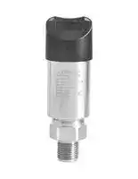


PSW2100-005C
PRESSURE SWITCH, 2PNP, 5PSI, 1/4" NPTM
- Manufacturer: OMEGA
- Product type: Pressure Switches
- Pressure Type:Gauge; Pressure Port Type:NPT Male; Operating Pressure Min:0psi; Operating Pressure Max:5psi; Contact Configuration:-; Switching Current Max:-; Pr 71AH2332
- Deadband Max: 5psi
- Deadband Min: 0psi
- Pressure Type: Gauge
- Product Range: PSW2100 Series
- Sensor Mounting: Stud
- Pressure Port Size: 1/4"
- Pressure Port Type: NPT Male
- Contact Configuration: -
- Electrical Connection: M12 Connector
- Switching Current Max: -
- Switching Voltage Max: -
- Operating Pressure Max: 5psi
- Operating Pressure Min: 0psi
- Operating Temperature Max: 85°C
- Operating Temperature Min: -40°C
- Transducer Connection / Termination: 5 Pin M12 Connector
| Delivery and price | |
|---|---|
| Units per pack | 1 |
| Price | 580.83 € |
| Current stock | 10+ |
| Lead time | 30 days |
## **PS   2100W**

**==> picture [40 x 19] intentionally omitted <==**

**----- Start of picture text -----**<br>
INSTRUCTION<br>SHEET<br>**----- End of picture text -----**<br>


## **M-5762/0320**

**Shop online at omega.com e-mail: info@omega.com For latest product manuals: omegamanual.info**

- A ! Pressure switch is powered by an external power supply. The power supply should be in accordance with relevant standards stipulated by energy limitation circuit, and special attention should be given to the high-voltage that may exist in the circuit.

Two pressure switches can be used to create a differential measurement system, commonly used in the filter control or closed container level measurement. Install pressure transmitter

Can be installed with adapters on the pipe directly.

Light-weight pressure switch can be mounted directly on the pressure leading tube. When installing the maximum torque force can not exceed 50Nm.

- AX !

After the pressure  vessel is stable, slowly open the shut-off valve to in start measuring.

Can be used for liquid level measurement in open container. Media compatibility should be considered.

**==> picture [219 x 88] intentionally omitted <==**

**----- Start of picture text -----**<br>
4 3<br>1 2<br>1 2 3 4 5<br>Power+ Transistor output 2 Power- Transistor output 1 *Signal+<br>**----- End of picture text -----**<br>


*Signal:  4~20mA, 1-5VDC

**==> picture [214 x 87] intentionally omitted <==**

**----- Start of picture text -----**<br>
Power Signal<br>| P+ P e | S - S+<br>Label<br>1 2<br>brown/1 +<br>cor 28 e)<br>white/2 SW1 5 R1 4<br>Vi~~ PT blue/3 S+ +5,<br>4 3 black/4 - 3<br>(GC 1 [>)] 2 [ 5] CT gray/5 SW2 [atone] 6 R2<br>4/black wire is the common port<br>**----- End of picture text -----**<br>


   - A zero point adjustment should be made after installation to counter any effects the mounting position may have on the zero setting.

   - When performing the adjustment, the vessel should be completely empty, with no pressure or media on the measuring diaphragm and the vessel exposed to atmospheric air.

   - With unit powered, short the key-z wire (blue) to the + power lead. hold for 5 seconds, when removed the zero point will be adjusted. Set the zero point three weeks after installation to ensure accuracy, and reset zero point annually.

   - Set PV=0 each year.

- O 1 Connect the positive power supply (P+) to the terminal 1/brown ; wire of pressure switch;

- O 2 Connect the negative signal module (S-) to the negative power supply(P-);

- O 3 Connect the negative signal module (S-) to the negative power supply(P-) and then connect to the terminal 4/black wire of pressure switch;

Please observe the following when cleaning:

   - Use a cleaner that is compatible with pressure switch materials

   - Clean carefully to ensure that the pressure port isn't damaged (e.g. with a sharp object)

- O 4 Connect the positive signal module (S+) to the terminal 3/blue wire . Do not directly spray electrical connection or gauge vent with water of pressure switch; or cleaner.

- O 5 Connect the first way transistor to the terminal 2/white wire of pressure switch; Transportation / storage

- O 6 Connect the second way transistor to the terminal 5/gray wire of pressure switch. a Do not store outside.

- /£\ ! The signal connection of 4~20mA + two way NPN output is similar

- Keep dry and dust-free.

- Do not expose to the corrosive medium.

- Avoid solar radiation.

- Avoid mechanical shock and vibration.

- Storage temperature: -40-185℉(-40-85℃).

A zero point adjustment should be made after installation to counter any effects the mounting position may have on the zero setting. When performing the adjustment, the vessel should be completely empty, with no pressure or media on the measuring diaphragm and the vessel exposed to atmospheric air. With unit powered, short the key-z wire (blue) to the + power lead. hold for 5 seconds, when removed the zero point will be adjusted.Set the zero point three weeks after installation to ensure accuracy, and reset zero point annually.

   - Maximum relative humidity: 95%.

   - EMC equipment instructions 2014/30/EU.

   - CE mark suggests the instruments are in line with EU standards

   - Users need to ensure the whole equipment conform to all the applicable standards.

- Standard current signal output+transistor output: 12-30VDC,

- Transistor output: 12-30VDC.

- A cable with a shielded twisted-pair signal is recommended to avoid ground loop.

- The built-in transient resistance module is only effective if properly grounded. The metal body and internal grounding terminals should be directly grounded.

To safeguard against liquid media potentially traveling along the cable into the terminal box, the cable should be configured in a U-shape as shown, with the bottom of the “U” lower than the bottom of the pressure switch.

|Lable|Item|Setting range|Description|
|---|---|---|---|
|SPx(Note1)|OUT upper limit|-<br>~<br>99999 99999|Upper limit value of transistor output|
|Rpx|OUT lower limit|-<br>~<br>99999 99999|Lower limit value of transistor output|
|SPDTx|OUT output delay|0 0 60.0(S)<br>. ~|Delay time before transistor output active|
|RPDTx|OUT reset delay|0 0 60 0(S<br>. ~<br>.<br>)|Delay time before transistor output reset|
|Modex|OUT<br>working mode|Modex=0|No output. OUTx keeps reset state|
|||Modex=1|Measured value > SPx, delay SPDTx, OUTx active (Note2)|
||||Measured value < RPx, delay RPDTx, OUTx reset (0V, the same below)|
|||Modex=2|Measured value > SPx, delay SPDTx, OUTx reset|
||||Measured value < RPx, delay RPDTx, OUTx active|
|||Modex=3|RPx < measured value < SPx, delay SPDTx, OUTx active|
||||Measured value > SPx or measured value < RPx, delay RPDTx, OUTx reset|
|||Modex=4|Measured value > SPx or measured value < RPx, delay SPDTx, OUTx active|
||||RPx < measured value < SPx, delay RPDTx, OUTx reset|


Notes: 1. x =1 or 2, SPx ≥ RPx

2. Active electrical level is 2V lower than power supply level. Eg, power supply level is 24V, then active electrical level is 22V.

**==> picture [248 x 410] intentionally omitted <==**

**----- Start of picture text -----**<br>
P P: pressure<br>T: time<br>SPx<br>x=1 or 2<br>RPx<br>T<br>OUT<br>Modex=0,No output<br>Active<br>Reset T<br>OUT<br>Modex=1,HNO(Upper limit alarm/ hysteresis function)<br>Active<br>Reset SPDTx RPDTx T<br>OUT<br>Modex=2,HNC(Lower limit alarm/ hysteresis function)<br>Active<br>Reset T<br>RPDTx SPDTx<br>OUT<br>Modex=3,FNO(Window mode/ delayed alarm in window)<br>Active<br>Reset SPDTx RPDTx SPDTx RPDTx T<br>OUT<br>Modex=4,FNC(Window mode/ delayed alarm out window)<br>Active<br>Reset T<br>RPDTx SPDTx RPDTx SPDTx<br>**----- End of picture text -----**<br>


## High level alarm

Output alarm signal when pressure is higher than 145Psi. Normal setting: SP1=145Psi, RP1=137.78Psi, Mode1=1, SPDT1=1, RPDT1=1. Pressure rises to 145Psi, delay 1s, OUT1 active (on); pressure drops to 137.78Psi, delay 1s, OUT1 reset (off)

## Low level alarm

Output alarm signal when pressure is lower than 145Psi. Normal setting: RP1=145Psi, SP1=152.28Psi, Mode1=2, SPDT1=1, RPDT1=1. Pressure drops to 145Pssi, delay 1s, OUT1 active (on); pressure rises to 152.28Psi, delay 1s, OUT1 reset (off)

## Window function

Starting devices normally requires pressure is within the range 72.51~145Psi. Normal setting: SP1=145Psi, RP1=72.51Psi, Mode1=3, SPDT1=1, RPDT1=1. Pressure rises to 145Psi, delay 1s, OUT1 active (on); pressure rises to 145Psi, delay 1s, OUT1 reset (off); Pressure drops to 145Psi, delay 1s, OUT1 active (on); pressure drops to 72.51Psi, delay 1s, OUT1 reset (off)

## Automatically keep pressure function

Applying pressure on a device by a compressor and keeping the pressure within the range 72.51~145Psi need two ways output. The first way output controls the compressor and the second way output controls the device. The first way output setting: SP1=130.53Psi, RP=87.02Psi, Model=2, SPDT1=1, RPDT1=1. The first way contact controls the power supply of compressor through intermediate relay to disconnect once the pressure is higher than 130.53Psi and connect once the pressure is lower than 87.02Psi. The pressure value needs to be controlled within 87.02~130.53MPa. The second way output setting: SP2=145Psi, RP2=72.51Psi, Mode2=3, SPDT2=1, RPDT2=1. Once the working pressure of device is not within the range

72.51Psi~145Psi, after 1s, the second way contact controls the alarm output of  the device through intermediate relay to ensure the abnormal working pressure of the device can be discovered and handled in time.

Display module is used for field adjustment to complete all the parameters setting and site configuration before measuring.

For example, factory setting parameters: pressure range -10-100Psi, display unit Psi, operate in the atmosphere.

**==> picture [536 x 482] intentionally omitted <==**

**----- Start of picture text -----**<br>
Press  ive)  + Z M  at the<br>Press  at least 3  .?) M same time at least  Release  ive)  + Z M  at the<br>0.010 seconds 0.010 3 seconds 0.000 same time 0.000<br>Psi Psi PVC1r Success! Psi<br>e e e ee<br>Lo] Measuring interface [Lo] Measuring interface with lock Lo Finished interface<br>Span adjustment<br>Press  (ae)  + S M  at the<br>Press  at least 3  .?) M same time at least  Release  ae)  + S M  at the<br>100.10 seconds 100.10 3 seconds 100.00 same time 100.00<br>Psi Psi URV Cal Success! Psi<br>fftef fo mpmnf fre |<br>Measuring interface | Measuring interface with lock [ Successful interface Lo Finished interface<br>180° shift display<br>Press  aRv) S [+] Z  at the<br>Press  at least 3  ° M same time at least  Release  fay) S [+] Z  at the  Psi<br>0.010 seconds 0.010 3 seconds 0.010 same time<br>010.0<br>Psi Psi Rotating Success!<br>es ees e e<br>Measuring interface Measuring interface with lock Successful interface Finished interface<br>Lo] Lo<br>Check peak pressure<br>Press  at least 3 M Press  at least 3 S Max Pressure:<br>0.010 Se seconds ae 0.010 seeeeeeteseee seconds ereeeeeeeeeees 100.00 Saeeeaaeiaee Press   aee.?) M 0.010<br>Psi Psi M key for exit! Psi<br>Measuring interface Measuring interface with lock Successful interface Finished interface<br>Press  at least 3 S<br>seconds<br>Data cleared!<br>0.010 Release  S<br>Will be exit! Successful interface<br>Switch to lock/unlock<br>Press  at least 3  O° M Press  at least 3  ° M<br>seconds seconds<br>0.010 0.010 0.010<br>Psi Psi Psi<br>[ Measuring interface [ Measuring interface with lock [ Measuring interface<br>**----- End of picture text -----**<br>


**==> picture [535 x 628] intentionally omitted <==**

**----- Start of picture text -----**<br>
0.010 Power off Press , power onZ Data restore OKPlease free the key! Release  Z 0.010<br>Psi Psi<br>Measuring interface Interface before power on Successful interface Finished interface<br>Press , power onZ Data restore OKPlease free the key! Release  Z 0.010<br>Psi<br>Interface before power on Interface before power on Finished interface<br>Pressure    &    Unit Pressure    &    Unit   modify S SPn      P   &   RPn&<br>  enter settingsZ parameters<br>0.010   confirm M 0   confirm and M 0 2 0 Pressure & Unit Two rows display: PV & Unit<br>Measuring interfacePsi next menuand enter  Current parametersDisMod enter next menu Set parametersDisMod Display modified parametersDisMod 12 XXX% & P & UnitSpn & P  Three rows display: percentage; pv & unitThree rows display:<br>& RPn SP1&RP1 alternate<br>display, SP2&RP2<br>alternate display<br>  confirm and enter next menuZ<br>Ran:-99999~99999 Ran:-99999~99999   modify S Ran:-99999~99999<br>  enter settingsZ parameters -99999~99999<br>-10.00 -10.00 -10.01<br>  confirm and M<br>LRV LRV LRV<br>enter next menu<br>Current parameters Display selected parameters Display modified parameters<br>  confirm and enter next menuZ -99999~99999<br>Ran:-99999~99999 Ran:-99999~99999   modify S Ran:-99999~99999<br>  enter settingsZ parameters<br>100.00 100.00 100.01<br>  confirm and M<br>URV URV URV<br>enter next menu 0     -<br>current parameters Display selected parameters Display modified parameters 1 kPa<br>2 MPa<br>3 Pa<br>4 bar<br>5 mBar<br>6 Psi<br>7 mH2O<br>kPa  1   enter settingsZ kPa  1 parameters  modify S Mpa  2 891011 mmH2O  cmH2OmmHgTorr<br>  confirm and M 12 Atm<br>Unit Unit Unit<br>enter next menu<br>Current parameters Display selected parameters Display modified parameters<br>0    Auto Optimal display mode<br>1 xxxxx Integer, no decimal<br>2 xxxx.x One decimal<br>XXXXX xxxxx   modify S XXXX.X 3 xxx.xx Two decimal<br> 1   enter settingsZ  1 parameters  2 45 xx.xxxx.xxxx Three decimalFour decimal<br>  confirm and M<br>DotPos DotPos DotPos<br>enter next menu<br>Current parameters Display selected parameters Display modified parameters<br>**----- End of picture text -----**<br>


**==> picture [532 x 471] intentionally omitted <==**

**----- Start of picture text -----**<br>
  confirm and enter next menuZ<br>-99999~99999<br>Ran:-99999~99999 Ran:-99999~99999   modify S Ran:-99999~99999<br>Press  S   enter settingsZ parameters<br>0.010 90.00 90.00 90.01<br>  confirm and M<br>kPa SP1 enter next menu SP1 SP1<br>Measuring interface Current parameters Display selected parameters Display modified<br>parameters<br>  confirm and enter next menuZ<br>Ran:-99999~99999 Ran:-99999~99999   modify S Ran:-99999~99999<br>  enter settingsZ parameters -99999~99999<br>80.00 80.00 80.01<br>  confirm and M<br>RP1 RP1 RP1<br>enter next menu<br>Current parameters Display selected parameters Display modified<br>parameters<br>  confirm and enter next menuZ<br>Ran:0.00~60.0S Ran:0.00~60.0S   modify S Ran:0.00~60.0S 0.0-60.0S<br>  enter settingsZ parameters<br>0.0 0.0 0.1<br>  confirm and M<br>RPDT1 RPDT1 RPDT1<br>enter next menu<br>Current parameters Display selected parameters Display modified<br>parameters<br>  confirm and enter next menuZ<br>Ran:0.00~60.0S Ran:0.00~60.0S   modify S Ran:0.00~60.0S<br>  enter settingsZ parameters<br>0.0-60.0S<br>0.010 0.0 0.0 0.1<br>  confirm and M<br>kPa SPDT1 enter next menu SPDT1 SPDT1<br>Measuring interface Current parameters Display selected parameters Display modified<br>parameters<br>0 No Out<br>1 Hysteresis, >P SPn<br>2 Hysteresis, <P RPn<br>No Out No Out   modify S Hysteresis, >P SPn 34 WindowWindow, , <RPnP RPn<P<, <PSPnSPn<br>  enter settingsZ parameters<br>0 0 1<br>  confirm and M<br>Mode1 Mode1 Mode1<br>enter next menu<br>Current parameters Display selected parameters Display modified<br>parameters<br>**----- End of picture text -----**<br>


**==> picture [535 x 502] intentionally omitted <==**

**----- Start of picture text -----**<br>
-99999~99999<br>  confirm and enter next menuZ<br>Ran:-99999~99999 Ran:-99999~99999   modify S Ran:-99999~99999<br>Press  Z   enter settingsZ parameters<br>0.010 50.00 50.00 50.01<br>  confirm and M<br>kPa SP2 SP2 SP2<br>enter next menu<br>Measuring interface Current parameters Display selected parameters Display modified<br>parameters<br>-99999~99999<br>Ran:-99999~99999 Ran:-99999~99999   modify S Ran:-99999~99999<br>30.00   enter settingsZ 30.00 parameters 30.01<br>  confirm and M<br>RP2 RP2 RP2<br>enter next menu 0 0. -60 0S.<br>Current parameters Display selected parameters Display modified<br>parameters<br>  confirm and enter next menuZ<br>Ran:0.00~60.0S Ran:0.00~60.0S   modify S Ran:0.00~60.0S<br>  enter settingsZ parameters<br>0.0 0.0 0.1<br>  confirm and M<br>SPDT2 SPDT2 SPDT2<br>enter next menu<br>Current parameters Display modified parameters Display modified<br>parameters<br>  confirm and enter next menuZ<br>0 0. -60 0S.<br>Ran:0.00~60.0S Ran:0.00~60.0S   modify S Ran:0.00~60.0S<br>  enter settingsZ parameters<br>0.0 0.0 0.1<br>  confirm and M<br>RPDT2 RPDT2 RPDT2<br>enter next menu<br>Current parameters Display modified parameters Display modified<br>parameters<br>  confirm and enter next menuZ<br>0 No Out<br>1 Hysteresis, >P SPn<br>No Out No Out   modify S Hysteresis, >P SPn 2 Hysteresis, <P RPn<br>  enter settingsZ parameters 3 Window, RPn<P<SPn<br>0 0 2 4 Window, <P RPn, <P SPn<br>  confirm and M<br>Mode2 Mode2 Mode2<br>enter next menu<br>Current parameters Display modified parameters Display modified<br>parameters<br>**----- End of picture text -----**<br>


**==> picture [533 x 34] intentionally omitted <==**

**==> picture [535 x 140] intentionally omitted <==**

**----- Start of picture text -----**<br>
Power off Press , power onM It will display all Release  M<br> 0.010 parameters! Please free  0.010<br>the key!<br>Psi Psi<br>Current parameters Interface before power on Finished interface Finished interface<br>Press , power onM It will display all Release  M<br>parameters! Please free  0.010<br>the key!<br>Psi<br>Interface before power on Successful interface Finished interface<br>**----- End of picture text -----**<br>


After above operation, press M get into DisMod-LRV-Unit parameters setting,and press M again get into hidden parameters setting

**==> picture [535 x 435] intentionally omitted <==**

**----- Start of picture text -----**<br>
  confirm and enter next menuZ<br>Ran:3.500~3.800 Ran:3.500~3.800   modify S Ran:3.500~3.800<br>  enter settingsZ parameters<br> 3.700  3.700  3.701<br>  confirm and M 3.500-3.800mA<br>mA       AOLC mA       AOLC mA       AOLC<br>enter next menu<br>Current parameters Display selected parameters Display modified<br>parameters<br>  confirm and enter next menuZ<br>Ran:20.800~24.000 Ran:20.800~24.000   modify S Ran:20.800~24.000 20.800-24.000mA<br>  enter settingsZ parameters<br> 23.000  23.000  23.001<br>  confirm and M<br>mA       AOHC mA       AOHC mA       AOHC<br>enter next menu<br>Current parameters Display selected parameters Display modified<br>parameters<br>0 Measuring Output<br>1 Output 3.800mA<br>Measuring Output 0   enter settingsZ Measuring Output0 parameters  modify S Output    3.800mA1 2345 Output 4.000mAOutput 8.000mAOutput 12.000mAOutput 16.000mA<br>  confirm and M 6 Output 20.000mA<br>Fix COut enter next menu Fix COut Fix COut 7 Output 20.800mA<br>Current parameters Display selected parameters Display modified<br>parameters<br>0 Both Off!<br>1 Fist On!<br>Both off 0   enter settingsZ 0 parameters  modify S 1 23 Second On!Both On!<br>0.010<br>  confirm and M<br>kPa FixTOut enter next menu Fix TOut FixTOut<br>Measuring interface Current parameters Display selected parameters Display modified<br>parameters<br>  confirm the output Z<br>**----- End of picture text -----**<br>


Note 1: By default, the system shows optimal precision according to measuring range. Eg: While the measuring range of product is 0-10kPa, measuring value shows 0.000-10.000; while the measuring range of product is 0-100kPa, the measuring value shows 0.00-100.00. If DotPos parameters value and measuring range do not match, the system will automatically ignore and then process by default.

Eg: While the measuring range of product is 0-10kPa, if operator makes DotPos=5, the system will regard it as ineffectiveness and the measuring value will still shows 0.000-10.000 by default; while the measuring range of product is 0-100kPa, if operator makes DotPos=4 or 5, the system will regard it as ineffectiveness and the measuring value will still shows 0.00-100.00 by default.

Note 2:Use FixCOut parameters to control fixed current ,to confirm whether current output is ok. Changing fixed current value by press S and confirm by Z.

Note 3:Use FixTOut parameters to control 2 way PNP by mannual operation, to confirm whether PNP output is ok. Changing fixed current value by press S and confirm by Z.

**==> picture [565 x 220] intentionally omitted <==**

8
Updated at June 9, 2026
Omega is a globally recognized leader in the design and manufacture of state-of-the-art products for process measurement and control. Renowned for its engineering expertise, the company provides highly reliable solutions for monitoring critical parameters such as temperature, humidity, pressure, strain, and flow across diverse industrial applications. Our extensive selection of Omega products is focused on the brand's core strengths in sensing and automation technologies. The range features a vast array of high-precision temperature sensors, including industry-standard thermocouples and RTDs, supported by a comprehensive selection of essential sensor accessories. To complement these measurement devices, we offer a substantial lineup of robust temperature controllers and advanced pressure transducers engineered to maintain precise conditions in demanding environments. Beyond primary sensing and control, the Omega portfolio encompasses sophisticated panel instrumentation for clear process visualization, alongside highly accurate force sensors and load cells. The offering is completed by reliable signal converters, data acquisition tools such as dataloggers, and fundamental connectivity components, providing professionals with the specialized equipment necessary to build complete, end-to-end industrial control systems.
About Novapart
Novapart is a B2B electronic component broker specialising in stock shortages and cost reduction. We source hard-to-find parts and identify compliant alternatives across a catalogue of 410,000+ components from 500+ manufacturers.
Learn more →Stock Shortage Specialist
When a component is unavailable, discontinued or has an unacceptable lead time, we tap into our network of vetted European and Asian distributors to source what you need — without compromising on quality or traceability.
Request a quote →Compliant Alternatives
We identify pin-to-pin, electrically equivalent substitutes that meet the same certifications (RoHS, AEC-Q100, REACH) as your original specification — validated against datasheets, not just part numbers. Often at a lower cost.
BOM Analysis service →