
Image not available
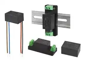
Illustrative purposes only

PSK-S5B-12-T
AC/DC Enclosed Power Supply (PSU), ITE, 1 Outputs, 5 W, 12 VDC, 420 mA
⚠️ Reference pricing provided. In case of supply shortages, we will connect you with our trusted procurement partners to ensure your project's continuity.
- Manufacturer: CUI
- Product type: AC / DC Enclosed Power Supplies
- Available until stocks are exhausted
- SVHC: To Be Advised
- Product Range: PSK-S5B Series
- No. of Outputs: 1Outputs
- Output Power Max: 5W
- Input Voltage VAC: 85V AC to 264V AC
- Power Supply Output Type: Fixed
- Output Current - Output 1: 420mA
- Output Current - Output 2: -
- Output Current - Output 3: -
- Output Current - Output 4: -
- Output Voltage - Output 1: 12VDC
- Output Voltage - Output 2: -
- Output Voltage - Output 3: -
- Output Voltage - Output 4: -
- Power Supply Applications: ITE
| Delivery and price | |
|---|---|
| Units per pack | 10 |
| Price | 12.61 € |
| Current stock | 25+ |
| Lead time | 30 days |
Datasheet

Additional Resources:    Product Page ~~OB~~ |    3D Model |    PCB Footprint

**date** 09/13/2022 **page** 1 of 8

## **SERIES:** PSK-S5B **DESCRIPTION:** AC-DC POWER SUPPLY **│**

## **FEATURES**

- universal input range (85 ~ 264 Vac)

- wide operating temperature range (-40 to +70 °C)

- 4K Vac minimum isolation voltage

- over-current, over-voltage, and short-circuit protection

- low-profile encapsulated package (18 mm / 0.709”)

- 85 mm (3.346”) leaded configuration available with

- “-L” suffix

- chassis-mount configuration available with “-T” suffix

- DIN-rail configuration available with “-DIN” suffix

|**MODEL**|**output**<br>**voltage**|**output**<br>**current**|**output**<br>**current**|**output**<br>**power**|**ripple**<br>**and noise1**|**efficiency2**|
|---|---|---|---|---|---|---|
|||**min**|**max**|**max**|**max**|**typ**|
||(Vdc)|(mA)|(mA)|(W)|(mVp-p)|**(%)**|
|PSK-S5B-34,5,6,7|3.3|0|1000|3.3|100|68|
|PSK-S5B-54,5,6|5|0|1000|5|100|75|
|PSK-S5B-94,5,6,7|9|0|560|5|100|77|
|PSK-S5B-124,5,6,7|12|0|420|5|100|79|
|PSK-S5B-154,5,6,7|15|0|330|5|100|79|
|PSK-S5B-244,5,6,7|24|0|210|5|100|81|


- Notes: 1. At full load, nominal input, 20 MHz bandwidth oscilloscope, with 1 µF ceramic and 10 µF electrolytic capacitors on the output.

2. At 230 Vac input.

3. All specifications are measured at Ta=25°C, humidity <75%, nominal input voltage, and rated output load unless otherwise specified.

4. Board mount option discontinued.

5. DIN-rail mount option discontinued.

6. Lead wires mount option discontinued.

7. Chassis mount option discontinued.

## **PART NUMBER KEY**

**- - - PSK S5B XX X** ~~ZT~~ Base Number Output Voltage Mounting Style: “blank” = board mount L = lead wires T = chassis mount DIN = DIN-rail mount

**cui** .com

Additional Resources:    Product Page    |    3D Model |    PCB Footprint

**CUI Inc │ SERIES:** PSK-S5B **│ DESCRIPTION:** AC-DC POWER SUPPLY

**date** 09/13/2022 **│ page** 2 of 8

|**INPUT**|**INPUT**|
|---|---|
|**parameter**<br>**conditions/description**<br>**min**<br>**typ**<br>**max**<br>**units**||
|voltage<br>85<br>100<br>264<br>370<br>Vac<br>Vdc||
|frequency<br>47<br>63<br>Hz||
|current<br>at 115 Vac<br>at 230 Vac<br>130<br>70<br>mA<br>mA||
|inrush current<br>at 115 Vac<br>at 230 Vac<br>10<br>20<br>A<br>A||
|leakage current<br>at 230 Vac, 50 Hz<br>0.1<br>mA||
|**OUTPUT**||
|**parameter**<br>**conditions/description**<br>**min**<br>**typ**<br>**max**<br>**units**||
|capacitive load<br>3, 5 Vdc output models<br>9, 12 Vdc output models<br>15 Vdc output models<br>24 Vdc output models<br>5000<br>1200<br>1000<br>330<br>µF<br>µF<br>µF<br>µF||
|initial set point accuracy<br>3.3 Vdc output models<br>all other models<br>±3<br>±2<br>%<br>%||
|line regulation<br>at full load<br>±0.5<br>%||
|load regulation<br>from 0~100% load<br>±1<br>%||
|hold-up time<br>at 115 Vac<br>at 230 Vac<br>5<br>50<br>ms<br>ms||
|switching frequency<br>100<br>kHz||
|temperature coefcient<br>±0.02<br>%/°C||
|**PROTECTIONS**||
|**parameter**<br>**conditions/description**<br>**min**<br>**typ**<br>**max**<br>**units**||
|over voltage protection<br>3, 5 Vdc output models<br>9 Vdc output models<br>12, 15 Vdc output models<br>24 Vdc output models<br>7.5<br>15<br>20<br>30<br>Vdc<br>Vdc<br>Vdc<br>Vdc||
|over current protection<br>auto recovery<br>120<br>%||
|short circuit protection<br>continuous, auto recovery||
|**SAFETY & COMPLIANCE**||
|**parameter**|**conditions/description**<br>**min**<br>**typ**<br>**max**<br>**units**|
|isolation voltage|input to output for 1 minute<br>4,000<br>Vac|
|safety approvals|UL 62368-1, EN 62368-1, IEC 62368-1|
|safety class|Class II|
|conducted emissions|CISPR32/EN55032, Class A|
||CISPR32/EN55032, Class B (external circuit required, see Figure 2)|
|radiated emissions|CISPR32/EN55032, Class A|
||CISPR32/EN55032, Class B (external circuit required, see Figure 2)|
|ESD|IEC/EN61000-4-2, contact ±6 kV/ air ±8kV, Class B|
|radiated immunity|IEC/EN61000-4-3, 10V/m, Class A|


**cui** .com

Additional Resources:    Product Page    |    3D Model |    PCB Footprint

**CUI Inc │ SERIES:** PSK-S5B **│ DESCRIPTION:** AC-DC POWER SUPPLY

**date** 09/13/2022 **│ page** 3 of 8

## **SAFETY & COMPLIANCE (CONTINUED)**

|**parameter**|**conditions/description**<br>**min**<br>**typ**<br>**max**<br>**units**|
|---|---|
|EFT/burst|IEC/EN61000-4-4, ±2 kV, Class B (external circuit required, see Figure 1)|
||IEC/EN61000-4-4, ±4 kV, Class B (external circuit required, see Figure 2)|
|surge|IEC/EN61000-4-5, line to line ±1 kV, Class B (external circuit required, see Figure 1)|
||IEC/EN61000-4-5, line to line ±1 kV/line to ground ±4 kV, Class B<br>(external circuit required, see Figure 2)|
|conducted immunity|IEC/EN61000-4-6, 10 Vrms, Class A|
|voltage dips & interruptions|IEC/EN61000-4-11 Class B, 0%-70%|
|MTBF|as per MIL-HDBK-217F at 25°C<br>300,000<br>hours|
|RoHS|yes|


Notes: 4. The power supply is considered a component which will be installed into final equipment.  The final equipment still must be tested to meet the necessary EMC directives.

## **ENVIRONMENTAL**

|**ENVIRONMENTAL**||||||
|---|---|---|---|---|---|
|**parameter**|**conditions/description**|**min**|**typ**|**max**|**units**|
|operating temperature|see derating curves|-40||70|°C|
|storage temperature||-40||105|°C|
|storage humidity|non-condensing|||95|%|
|**SOLDERABILITY5**||||||
|**parameter**|**conditions/description**|**min**|**typ**|**max**|**units**|
|hand soldering|for 3~5 seconds|350|360|370|°C|
|wave soldering|for 5~10 seconds|255|260|265|°C|


Notes: 5. For board mount models only

**==> picture [239 x 161] intentionally omitted <==**

**----- Start of picture text -----**<br>
Peak Temp. 260°C Max.<br>250 Wave Soldering Time<br>4 Sec. Max.<br>200<br>10 Sec. Max.<br>150<br>100<br>50<br>0<br>Time (sec.)<br>Temperature (°C)<br>**----- End of picture text -----**<br>


**cui** .com

Additional Resources:    Product Page    |    3D Model |    PCB Footprint

**CUI Inc │ SERIES:** PSK-S5B **│ DESCRIPTION:** AC-DC POWER SUPPLY

**date** 09/13/2022 **│ page** 4 of 8

## **DERATING CURVES**

## **EFFICIENCY CURVES**

**cui** .com

Additional Resources:    Product Page    |    3D Model |    PCB Footprint

**CUI Inc │ SERIES:** PSK-S5B **│ DESCRIPTION:** AC-DC POWER SUPPLY

**date** 09/13/2022 **│ page** 5 of 8

## **MECHANICAL**

|**MECHANICAL**|||||
|---|---|---|---|---|
|**parameter**|**conditions/description**<br>**min**|**typ**|**max**|**units**|
||board mount: 37.00 x 24.50 x 18.00 (1.457 x 0.965 x 0.709 inch)|||mm|
|dimensions|lead wires: 37.00 x 24.50 x 18.00 (1.457 x 0.965 x 0.709 inch)<br>chassis mount: 76.00 x 31.50 x 26.80 (2.992 x 1.24 x 1.055 inch)|||mm<br>mm|
||DIN-Rail mount: 76.00 x 31.50 x 31.40 (2.992 x 1.24 x 1.236 inch)|||mm|
|case material|black flame-retardant and heat-resistant plastic (UL94V-0)||||
||board mount|25||g|
|weight|lead wires<br>chassis mount|25<br>47||g<br>g|
||DIN-Rail mount|69||g|


## **MECHANICAL DRAWING (BOARD MOUNT)**

units: mm[inch] tolerance: ±0.50[±0.020] pin diameter tolerance: ±0.10[±0.004]

|PIN CONNECTIONS|PIN CONNECTIONS|
|---|---|
|PIN|Function|
|1|AC (L)|
|3|AC (N)|
|13|NC|
|14|-Vo|
|16|+Vo|


Recommended PCB Layout Top View

## **MECHANICAL DRAWING (LEAD WIRES)**

units: mm [inch] tolerance: ±0.50[±0.020] wire diameter tolerance: ±0.30[±0.012]

|WIRE CONNECTIONS|WIRE CONNECTIONS|WIRE CONNECTIONS|WIRE CONNECTIONS|
|---|---|---|---|
|PIN|COLOR|WIRE TYPE|Function|
|1|brown|UL-1015 22 AWG|AC (L)|
|3|blue|UL-1015 22 AWG|AC (N)|
|14|black|UL-1430 22 AWG|-Vo|
|16|red|UL-1430 22 AWG|+Vo|


**cui** .com

Additional Resources: Product Page    |    3D Model |    PCB Footprint

**CUI Inc │ SERIES:** PSK-S5B **│ DESCRIPTION:** AC-DC POWER SUPPLY

**date** 09/13/2022 **│ page** 6 of 8

## **MECHANICAL DRAWING (CHASSIS MOUNT)**

units: mm[inch] tolerance: ±0.50[±0.020]

wire range: 24~12 AWG tightening torque: max 0.4 N*m

|PIN CONNECTIONS|PIN CONNECTIONS|
|---|---|
|PIN|Function|
|1|AC (N)|
|2|AC (L)|
|3|-Vo|
|4|+Vo|


1 | ee Front View ee

## **MECHANICAL DRAWING (DIN-RAIL MOUNT)**

units: mm [inch] tolerance: ±1.00[±0.039]

installed on DIN Rail TS35 wire range: 24~12 AWG tightening torque: max 0.4 N*m

|PIN CONNECTIONS|PIN CONNECTIONS|
|---|---|
|PIN|Function|
|1|AC (N)|
|2|AC (L)|
|3|-Vo|
|4|+Vo|


**cui** .com

Additional Resources:    Product Page    |    3D Model |    PCB Footprint

**CUI Inc │ SERIES:** PSK-S5B **│ DESCRIPTION:** AC-DC POWER SUPPLY

**date** 09/13/2022 **│ page** 7 of 8

## **APPLICATION CIRCUIT**

**Figure 1**

**Table 1**

|**Table 1**|**Table 1**|**Table 1**|**Table 1**|**Table 1**|**Table 1**|
|---|---|---|---|---|---|
|Recommended External Circuit Components||||||
|Vo<br>(Vdc)|FUSE6|MOV6|C1|C2|TVS|
|3.3|1A/250V|S14K350|1 μF|150 μF|SMBJ7.0A|
|5|1A/250V|S14K350|1 μF|150 μF|SMBJ7.0A|
|9|1A/250V|S14K350|1 μF|120 μF|SMBJ12A|
|12|1A/250V|S14K350|1 μF|120 μF|SMBJ20A|
|15|1A/250V|S14K350|1 μF|120 μF|SMBJ20A|
|24|1A/250V|S14K350|1 μF|68 μF|SMBJ30A|


- Notes: 6. Chassis Mount and DIN-Rail Mount versions include the fuse and MOV components.

## **EMC RECOMMENDED CIRCUIT**

**Figure 2**

**Table 2**

|**Table 2**|**Table 2**|
|---|---|
|Recommended External Circuit Components||
|FUSE|2 A/250 V, slow fusing|
|MOV|S14K350|
|LCM|10~30 mH|
|CX|0.1 µF/275 Vac|
|L1|330 µH/ 2 A|
|CY1/CY2|1 nF/400 Vac|
|R0|33 Ω/3 W|


- Notes: 7. C1 is a ceramic capacitor used to filter high frequency noise.

8. C2 is an electrolytic capacitor and it is recommended to be high frequency and low impedance. For capacitance and current of capacitor, refer to the datasheet provided by the

manufacturer. Voltage derating of capacitor should be at least 80%.

   9. TVS is a recommended component to protect post-circuits (if converter fails).

**cui** .com

Additional Resources:    Product Page    |    3D Model |    PCB Footprint

**CUI Inc │ SERIES:** PSK-S5B **│ DESCRIPTION:** AC-DC POWER SUPPLY

**date** 09/13/2022 **│ page** 8 of 8

## **REVISION HISTORY**

|**rev.**|**description**|**date**|
|---|---|---|
|1.0|initial release|11/12/2018|
|1.01|companylogo updated|02/05/2021|
|1.02|fgures and circuit drawings updated|02/23/2021|
|1.03|UKCA mark added|05/27/2022|
|1.04|discontinued models PSK-S5B-3-DIN, PSK-S5B-5-DIN, PSK-S5B-9-DIN,<br>PSK-S5B-12-DIN, PSK-S5B-15-DIN, PSK-S5B-24-DIN, PSK-S5B-5-L,<br>PSK-S5B-3-T, PSK-S5B-9-T, PSK-S5B-15-T|06/29/2022|
|1.05|discontinued models PSK-S5B-3, PSK-S5B-3-L, PSK-S5B-5,<br>PSK-S5B-5-L, PSK-S5B-9, PSK-S5B-9-L, PSK-S5B-12, PSK-S5B-12-L,<br>PSK-S5B-12-T, PSK-S5B-15, PSK-S5B-15-L, PSK-S5B-24,<br>PSK-S5B-24-L, PSK-S5B-24-T|09/13/2022|


The revision history provided is for informational purposes only and is believed to be accurate.

**==> picture [119 x 38] intentionally omitted <==**

**Headquarters** 20050 SW 112th Ave. Fax 503.612.2383 Tualatin, OR 97062 **cui** .com **800.275.4899** techsupport@cui.com

CUI offers a two (2) year limited warranty.  Complete warranty information is listed on our website.

CUI reserves the right to make changes to the product at any time without notice.  Information provided by CUI is believed to be accurate and reliable.  However, no responsibility is assumed by CUI for its use, nor for any infringements of patents or other rights of third parties which may result from its use.

CUI products are not authorized or warranted for use as critical components in equipment that requires an extremely high level of reliability.  A critical component is any component of a life support device or system whose failure to perform can be reasonably expected to cause the failure of the life support device or system, or to affect its safety or effectiveness.
Updated at June 10, 2026
About Novapart
Novapart is a B2B electronic component broker specialising in stock shortages and cost reduction. We source hard-to-find parts and identify compliant alternatives across a catalogue of 410,000+ components from 500+ manufacturers.
Learn more →Stock Shortage Specialist
When a component is unavailable, discontinued or has an unacceptable lead time, we tap into our network of vetted European and Asian distributors to source what you need — without compromising on quality or traceability.
Request a quote →Compliant Alternatives
We identify pin-to-pin, electrically equivalent substitutes that meet the same certifications (RoHS, AEC-Q100, REACH) as your original specification — validated against datasheets, not just part numbers. Often at a lower cost.
BOM Analysis service →