
Image not available
Illustrative purposes only

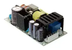
PSC-60B-C
AC/DC Enclosed Power Supply (PSU), ITE, 1 Outputs, 59.34 W, 27.6 VDC, 2.15 A
⚠️ Reference pricing provided. In case of supply shortages, we will connect you with our trusted procurement partners to ensure your project's continuity.
- Manufacturer: MEAN WELL
- Product type: AC / DC Enclosed Power Supplies
- SVHC: No SVHC (25-Jun-2025)
- Product Range: PSC-60 Series
- No. of Outputs: 1Outputs
- Output Power Max: 59.34W
- Input Voltage VAC: 90V AC to 305V AC
- Power Supply Output Type: Adjustable, Fixed
- Output Current - Output 1: 2.15A
- Output Current - Output 2: -
- Output Current - Output 3: -
- Output Current - Output 4: -
- Output Voltage - Output 1: 27.6VDC
- Output Voltage - Output 2: -
- Output Voltage - Output 3: -
- Output Voltage - Output 4: -
- Power Supply Applications: ITE
| Delivery and price | |
|---|---|
| Units per pack | 100 |
| Price | 15.6 € |
| Current stock | 10+ |
| Lead time | 30 days |
Datasheet

**PSC - 60 series**

## 60W Single Output with Battery Charger(UPS Function) Caen e rere reer reer e eee eee ee

## ■

## **SPECIFICATION**

**==> picture [11 x 14] intentionally omitted <==**

**----- Start of picture text -----**<br>
BauarSicherheitbeegelodwacmat geprufto ges g<br>www.ID 2000000000tuv.com<br>**----- End of picture text -----**<br>


|**MODEL**<br>**DC VOLTAGE**<br>**RATED CURRENT**<br>**CURRENT RANGE**<br>**RATED POWER**<br>**OUTPUT**<br>**VOLTAGE ADJ. RANGE**<br>**LINE REGULATION**<br>**LOAD REGULATION**<br>**SETUP, RISE TIME**<br>**Note.4**<br>**HOLD UP TIME (Typ.)**<br>**VOLTAGE RANGE**<br>**FREQUENCY RANGE**<br>**EFFICIENCY (Typ.)**<br>**INPUT**<br>**INRUSH CURRENT (Typ.)**<br>**LEAKAGE CURRENT**<br>**SAFETY STANDARDS**<br>**WORKING TEMP.**<br>**WORKING HUMIDITY**<br>**STORAGE TEMP., HUMIDITY**<br>**TEMP. COEFFICIENT**<br>**VIBRATION**<br>**MTBF**<br>**DIMENSION**<br>**OTHERS**<br>**NOTE**<br>**PACKING**<br>**OVERLOAD**<br>**OVER VOLTAGE**<br>**BATTERY CUT OFF**<br>**AC OK**<br>**BATTERY LOW**<br>**AC CURRENT (Typ.)**<br>800ms, 50ms/230VAC          1600ms, 50ms/115VAC at full load<br>50ms/230VAC          10ms/115VAC at full load<br>90 ~ 264VAC          127 ~ 370VDC<br>47 ~ 63Hz<br>84%<br>CH1:28.98 ~ 37.26V<br>84%<br>21<br>1V<br>±<br>Battery low voltage : < 22V<br>1.6A/115VAC          1A/230VAC<br>COLD START 30A/115VAC          60A/230VAC<br><1mA / 240VAC<br>105 ~ 150% rated output power<br>CH1:14.49 ~ 18.63V<br>Protection type : Hiccup mode, recovers automatically after fault condition is removed<br>Protection type : Hiccup mode, recovers automatically after fault condition is removed<br>10.5<br>0.5V<br>±<br>UL62368-1, TUV EN62368-1,<br>approved<br>EAC TP TC 004<br>Compliance to EN55032 (CISPR32) Class B, EN61000-3-2,-3, EAC TP TC 020<br>Compliance to EN61000-4-2,3,4,5,6,8,11, EN55024, light industry level,  criteria A, EAC TP TC 020<br>-20 ~ +70<br>(Refer to "Derating Curve")<br>℃<br>20 ~ 90% RH non-condensing<br>-20 ~ +85<br>, 10 ~ 95% RH<br>℃<br>±<br>℃<br>℃<br>0.03%/<br>(0~50<br>) on CH1 output<br>10 ~ 500Hz, 2G 10min./1cycle, 60min. each along X, Y, Z axes<br>589.7K hrs min.      MIL-HDBK-217F (25<br>)<br>℃<br>PCB:101.6*50.8*29mm (L*W*H) ; Enclosed type:103.4*62*37mm (L*W*H)<br>PCB:0.13Kg; 96pcs/13.5Kg/0.89CUFT ; Enclosed type:0.29Kg; 45pcs/14Kg/0.67CUFT<br>**FUNCTION**<br>TTL open collector output, ON : AC OK ; OFF : AC Fail ; Ice : max. 30mA@ 50VDC<br>TTL open collector output, ON : Battery Low ; OFF : Battery OK ; Ice : max. 30mA@ 50VDC<br>Battery low voltage : < 11V<br>**PSC-60B**<br>27.6V<br>CH1<br>1.4A<br>0 ~ 2.15A<br>59.34W<br>240mVp-p<br>CH1: 24 ~ 29V<br>±1.0%<br>±0.5%<br>±0.5%<br>27.6V<br>CH2<br>0.75A<br>--------<br>--------<br>--------<br>--------<br>--------<br>13.8V<br>CH2<br>1.5A<br>--------<br>--------<br>--------<br>--------<br>--------<br>**PSC-60A**<br>13.8V<br>2.8A<br>0 ~ 4.3A<br>59.34W<br>120mVp-p<br>CH1: 12 ~ 15V<br>±1.0%<br>±0.5%<br>±0.5%<br>**RIPPLE & NOISE (max.) Note.2**<br>**VOLTAGE TOLERANCE Note.3**<br>**ENVIRONMENT**<br>**PROTECTION**<br>**WITHSTAND VOLTAGE**<br>**ISOLATION RESISTANCE**<br>I/P-O/P:3KVAC     I/P-FG:2KVAC     O/P-FG:0.5KVAC<br>I/P-O/P, I/P-FG, O/P-FG:100M Ohms / 500VDC / 25<br>/ 70% RH<br>℃<br>**SAFETY &**<br>**EMC**<br>**(Note 7)**<br>℃<br>℃<br>℃<br>CH1<br>**OUTPUT NUMBER**<br>**EMC IMMUNITY**<br>**EMC EMISSION**<br>1. All parametersNOT specially mentioned are measured at230VAC input, rated load and 25 _of ambient temperature.<br>2. Ripple & noise are measured at 20MHz of bandwidth by using a 12" twisted pair-wire terminated with a 0.1uf & 47uf parallel capacitor.<br>3. Tolerance: includes set up tolerance, line regulation and load regulation.<br>4. Length of set up time is measured at first cold start. Turning ON/OFF the power supply may lead to increase of the set up time.<br>5. Heat sink HS1,HS2 can not be shorted.<br>6. Heat sink HS1 must have safety isolation distance with system case.<br>7. The power supply is considered a component which will be installed into a final equipment. All the EMC tests are been executed by mounting the unit on<br>a360mm*360mm metal plate with 1mm of thickness. The final equipment must be re-confirmed that it still meets EMC directives. For guidance on how to<br>perform these EMC tests, please refer to “EMI testing of component power supplies.” (as available on http://www.meanwell.com)<br>8. The ambient temperature derating of 3.5<br>/1000m with fanless models and of<br>5<br>/1000m with fan models for operating altitude higher than 2000m(6500ft)|**MODEL**<br>**DC VOLTAGE**<br>**RATED CURRENT**<br>**CURRENT RANGE**<br>**RATED POWER**<br>**OUTPUT**<br>**VOLTAGE ADJ. RANGE**<br>**LINE REGULATION**<br>**LOAD REGULATION**<br>**SETUP, RISE TIME**<br>**Note.4**<br>**HOLD UP TIME (Typ.)**<br>**VOLTAGE RANGE**<br>**FREQUENCY RANGE**<br>**EFFICIENCY (Typ.)**<br>**INPUT**<br>**INRUSH CURRENT (Typ.)**<br>**LEAKAGE CURRENT**<br>**SAFETY STANDARDS**<br>**WORKING TEMP.**<br>**WORKING HUMIDITY**<br>**STORAGE TEMP., HUMIDITY**<br>**TEMP. COEFFICIENT**<br>**VIBRATION**<br>**MTBF**<br>**DIMENSION**<br>**OTHERS**<br>**NOTE**<br>**PACKING**<br>**OVERLOAD**<br>**OVER VOLTAGE**<br>**BATTERY CUT OFF**<br>**AC OK**<br>**BATTERY LOW**<br>**AC CURRENT (Typ.)**<br>800ms, 50ms/230VAC          1600ms, 50ms/115VAC at full load<br>50ms/230VAC          10ms/115VAC at full load<br>90 ~ 264VAC          127 ~ 370VDC<br>47 ~ 63Hz<br>84%<br>CH1:28.98 ~ 37.26V<br>84%<br>21<br>1V<br>±<br>Battery low voltage : < 22V<br>1.6A/115VAC          1A/230VAC<br>COLD START 30A/115VAC          60A/230VAC<br><1mA / 240VAC<br>105 ~ 150% rated output power<br>CH1:14.49 ~ 18.63V<br>Protection type : Hiccup mode, recovers automatically after fault condition is removed<br>Protection type : Hiccup mode, recovers automatically after fault condition is removed<br>10.5<br>0.5V<br>±<br>UL62368-1, TUV EN62368-1,<br>approved<br>EAC TP TC 004<br>Compliance to EN55032 (CISPR32) Class B, EN61000-3-2,-3, EAC TP TC 020<br>Compliance to EN61000-4-2,3,4,5,6,8,11, EN55024, light industry level,  criteria A, EAC TP TC 020<br>-20 ~ +70<br>(Refer to "Derating Curve")<br>℃<br>20 ~ 90% RH non-condensing<br>-20 ~ +85<br>, 10 ~ 95% RH<br>℃<br>±<br>℃<br>℃<br>0.03%/<br>(0~50<br>) on CH1 output<br>10 ~ 500Hz, 2G 10min./1cycle, 60min. each along X, Y, Z axes<br>589.7K hrs min.      MIL-HDBK-217F (25<br>)<br>℃<br>PCB:101.6*50.8*29mm (L*W*H) ; Enclosed type:103.4*62*37mm (L*W*H)<br>PCB:0.13Kg; 96pcs/13.5Kg/0.89CUFT ; Enclosed type:0.29Kg; 45pcs/14Kg/0.67CUFT<br>**FUNCTION**<br>TTL open collector output, ON : AC OK ; OFF : AC Fail ; Ice : max. 30mA@ 50VDC<br>TTL open collector output, ON : Battery Low ; OFF : Battery OK ; Ice : max. 30mA@ 50VDC<br>Battery low voltage : < 11V<br>**PSC-60B**<br>27.6V<br>CH1<br>1.4A<br>0 ~ 2.15A<br>59.34W<br>240mVp-p<br>CH1: 24 ~ 29V<br>±1.0%<br>±0.5%<br>±0.5%<br>27.6V<br>CH2<br>0.75A<br>--------<br>--------<br>--------<br>--------<br>--------<br>13.8V<br>CH2<br>1.5A<br>--------<br>--------<br>--------<br>--------<br>--------<br>**PSC-60A**<br>13.8V<br>2.8A<br>0 ~ 4.3A<br>59.34W<br>120mVp-p<br>CH1: 12 ~ 15V<br>±1.0%<br>±0.5%<br>±0.5%<br>**RIPPLE & NOISE (max.) Note.2**<br>**VOLTAGE TOLERANCE Note.3**<br>**ENVIRONMENT**<br>**PROTECTION**<br>**WITHSTAND VOLTAGE**<br>**ISOLATION RESISTANCE**<br>I/P-O/P:3KVAC     I/P-FG:2KVAC     O/P-FG:0.5KVAC<br>I/P-O/P, I/P-FG, O/P-FG:100M Ohms / 500VDC / 25<br>/ 70% RH<br>℃<br>**SAFETY &**<br>**EMC**<br>**(Note 7)**<br>℃<br>℃<br>℃<br>CH1<br>**OUTPUT NUMBER**<br>**EMC IMMUNITY**<br>**EMC EMISSION**<br>1. All parametersNOT specially mentioned are measured at230VAC input, rated load and 25 _of ambient temperature.<br>2. Ripple & noise are measured at 20MHz of bandwidth by using a 12" twisted pair-wire terminated with a 0.1uf & 47uf parallel capacitor.<br>3. Tolerance: includes set up tolerance, line regulation and load regulation.<br>4. Length of set up time is measured at first cold start. Turning ON/OFF the power supply may lead to increase of the set up time.<br>5. Heat sink HS1,HS2 can not be shorted.<br>6. Heat sink HS1 must have safety isolation distance with system case.<br>7. The power supply is considered a component which will be installed into a final equipment. All the EMC tests are been executed by mounting the unit on<br>a360mm*360mm metal plate with 1mm of thickness. The final equipment must be re-confirmed that it still meets EMC directives. For guidance on how to<br>perform these EMC tests, please refer to “EMI testing of component power supplies.” (as available on http://www.meanwell.com)<br>8. The ambient temperature derating of 3.5<br>/1000m with fanless models and of<br>5<br>/1000m with fan models for operating altitude higher than 2000m(6500ft)|**PSC-60A**|**PSC-60A**|**PSC-60B**|**PSC-60B**|
|---|---|---|---|---|---|
||**OUTPUT NUMBER**|CH1|CH2|CH1|CH2|
||**DC VOLTAGE**|13.8V|13.8V|27.6V|27.6V|
||**RATED CURRENT**|2.8A|1.5A|1.4A|0.75A|
||**CURRENT RANGE**|0 ~ 4.3A|--------|0 ~ 2.15A|--------|
||**RATED POWER**|59.34W||59.34W||
||**RIPPLE & NOISE (max.) Note.2**|120mVp-p|--------|240mVp-p|--------|
||**VOLTAGE ADJ. RANGE**|CH1: 12 ~ 15V||CH1: 24 ~ 29V||
||**VOLTAGE TOLERANCE Note.3**|±1.0%|--------|±1.0%|--------|
||**LINE REGULATION**|±0.5%|--------|±0.5%|--------|
||**LOAD REGULATION**|±0.5%|--------|±0.5%|--------|
||**SETUP, RISE TIME**<br>**Note.4**|800ms, 50ms/230VAC          1600ms, 50ms/115VAC at full load||||
||**HOLD UP TIME (Typ.)**|50ms/230VAC          10ms/115VAC at full load||||
||**VOLTAGE RANGE**|90 ~ 264VAC          127 ~ 370VDC||||
||**FREQUENCY RANGE**|47 ~ 63Hz||||
||**EFFICIENCY (Typ.)**|84%||84%||
||**AC CURRENT (Typ.)**|1.6A/115VAC          1A/230VAC||||
||**INRUSH CURRENT (Typ.)**|COLD START 30A/115VAC          60A/230VAC||||
||**LEAKAGE CURRENT**|<1mA / 240VAC||||
||**OVERLOAD**|105 ~ 150% rated output power<br>Protection type : Hiccup mode, recovers automatically after fault condition is removed||||
||**OVER VOLTAGE**|CH1:28.98 ~ 37.26V<br>CH1:14.49 ~ 18.63V<br>Protection type : Hiccup mode, recovers automatically after fault condition is removed||||
||**BATTERY CUT OFF**|10.5<br>0.5V<br>±||21<br>1V<br>±||
||**AC OK**|TTL open collector output, ON : AC OK ; OFF : AC Fail ; Ice : max. 30mA@ 50VDC||||
||**BATTERY LOW**|Battery low voltage : < 22V<br>TTL open collector output, ON : Battery Low ; OFF : Battery OK ; Ice : max. 30mA@ 50VDC<br>Battery low voltage : < 11V||||
||**WORKING TEMP.**|-20 ~ +70<br>(Refer to "Derating Curve")<br>℃||||
||**WORKING HUMIDITY**|20 ~ 90% RH non-condensing||||
||**STORAGE TEMP., HUMIDITY**|-20 ~ +85<br>, 10 ~ 95% RH<br>℃||||
||**TEMP. COEFFICIENT**|±<br>℃<br>℃<br>0.03%/<br>(0~50<br>) on CH1 output||||
||**VIBRATION**|10 ~ 500Hz, 2G 10min./1cycle, 60min. each along X, Y, Z axes||||
||**SAFETY STANDARDS**|UL62368-1, TUV EN62368-1,<br>approved<br>EAC TP TC 004||||
||**WITHSTAND VOLTAGE**|I/P-O/P:3KVAC     I/P-FG:2KVAC     O/P-FG:0.5KVAC||||
||**ISOLATION RESISTANCE**|I/P-O/P, I/P-FG, O/P-FG:100M Ohms / 500VDC / 25<br>/ 70% RH<br>℃||||
||**EMC EMISSION**|Compliance to EN55032 (CISPR32) Class B, EN61000-3-2,-3, EAC TP TC 020||||
||**EMC IMMUNITY**|Compliance to EN61000-4-2,3,4,5,6,8,11, EN55024, light industry level,  criteria A, EAC TP TC 020||||
||**MTBF**|589.7K hrs min.      MIL-HDBK-217F (25<br>)<br>℃||||
||**DIMENSION**|PCB:101.6*50.8*29mm (L*W*H) ; Enclosed type:103.4*62*37mm (L*W*H)||||
||**PACKING**<br>PCB:0.13Kg; 96pcs/13.5Kg/0.89CUFT ; Enclosed type:0.29Kg; 45pcs/14Kg/0.67CUFT<br>℃<br>℃<br>℃<br>1. All parametersNOT specially mentioned are measured at230VAC input, rated load and 25 _of ambient temperature.<br>2. Ripple & noise are measured at 20MHz of bandwidth by using a 12" twisted pair-wire terminated with a 0.1uf & 47uf parallel capacitor.<br>3. Tolerance: includes set up tolerance, line regulation and load regulation.<br>4. Length of set up time is measured at first cold start. Turning ON/OFF the power supply may lead to increase of the set up time.<br>5. Heat sink HS1,HS2 can not be shorted.<br>6. Heat sink HS1 must have safety isolation distance with system case.<br>7. The power supply is considered a component which will be installed into a final equipment. All the EMC tests are been executed by mounting the unit on<br>a360mm*360mm metal plate with 1mm of thickness. The final equipment must be re-confirmed that it still meets EMC directives. For guidance on how to<br>perform these EMC tests, please refer to “EMI testing of component power supplies.” (as available on http://www.meanwell.com)<br>8. The ambient temperature derating of 3.5<br>/1000m with fanless models and of<br>5<br>/1000m with fan models for operating altitude higher than 2000m(6500ft)|||||


℃ /1000m with fanless models and of 5 ℃ /1000m with fan models for operating altitude higher than 2000m(6500ft) _File Name:PSC-60-SPEC   2019-06-10_

**PSC - 60 series**

## 60W Single Output with Battery Charger(UPS Function)

**==> picture [487 x 628] intentionally omitted <==**

**----- Start of picture text -----**<br>
Mechanical Specification Unit:mm<br>101.6<br>95.25 3.175 Cover:<br>No.998A -T<br>M2<br>HS2<br>FS1<br>AC FUSE<br>$ T2.5A/250V a6 SVR1 ee<br>3 [_] rc) 6 1 S BOgOOgOG OS ae<br>2<br>2<br>1 I CN1 —a 34 OORORSogoHN<br>5<br>6<br>M1 HS1 CN2<br>+ we @ [T .OX<><br>a ww & 4-ψ3.3 § eSSSP& si<br>SO DD re<br>Mylar film<br>1.HS1,HS2 can not be shorted. <S .<br>2.HS1 must have safety isolation distance with system case.<br>3.M1 is safety ground. For better EMC performance,Please<br>secure an electrical connection between M1,M2 and BSS<br>chassis grounding.<br>AC Input Connector (CN1) : JST B3P-VH or equivalent<br>SS<br>Pin No. Assignment Mating Housing Terminal<br>L-Bracket:<br>1 AC/N No.998A -D<br>JST VHR JST SVH-21T-P1.1<br>2 No Pin<br>or equivalent or equivalent<br>= 3 AC/L Sgwe<br>wo KO ®<br>DC Output Connector (CN2) : JST B6P-VH or equivalent Gi<br>Pin No. Assignment Pin No. Assignment Mating Housing Terminal —~<br>1 Bat. Low 4 Battery +<br>JST VHR JST SVH-21T-P1.1<br>2 AC OK 5 DC Output + or equivalent or equivalent<br>3 Battery - 6 DC Output COM<br>a : Grounding Required x<br>Block Diagram<br>ALARM AC OK<br>Bat. Low<br>CIRCUIT<br>E L O<br>EMI RECTIFIERS POWER RECTIFIERS +V<br>I/P FILTER & SWITCHING & a ee eee O e e -V<br>FILTER FILTER [| og Bat. +<br>DETECTION Bat. -<br>FG<br>CIRCUIT<br>O.L.P. CONTROL Battery Charger<br>&<br>O.V.P. Back Up Control<br>30.85<br>95 2-M3 L=4<br>78<br>62<br>2-ψ3.5<br>4.2<br>12.7 2-M3<br>2-M3 L=4<br>55<br>24.2<br>103.4<br>18 14.5<br>37<br>3 max.<br>3.175<br>50.8 44.45<br>29<br>**----- End of picture text -----**<br>


_File Name:PSC-60-SPEC   2019-06-10_

**PSC - 60 series**

60W Single Output with Battery Charger(UPS Function)

## **Output Derating**

**==> picture [152 x 12] intentionally omitted <==**

**----- Start of picture text -----**<br>
Output Derating VS Input Voltage<br>**----- End of picture text -----**<br>


**==> picture [452 x 146] intentionally omitted <==**

**----- Start of picture text -----**<br>
100<br>100<br>PCB only<br>90<br>80<br>80<br>Enclosed tpye<br>60 70<br>60<br>40<br>50<br>20<br>40<br>-20 0 10 20 30 35 40 50 60 70 (HORIZONTAL) 90 95 100 115 120 140 160 180 200 220 240 264<br>AMBIENT TEMPERATURE ( ℃ ) INPUT VOLTAGE (VAC) 60Hz<br>LOAD (%) LOAD (%)<br>**----- End of picture text -----**<br>


## **Suggested Application**

## **1.Backup connection for AC interruption**

- (1) Please refer to the Fig1.1 for suggested connection.

The power supply charges the battery and provides energy to the load at the same time when the AC main is OK.

The battery starts to supply power to the load when the AC mains fails.

**==> picture [121 x 100] intentionally omitted <==**

**----- Start of picture text -----**<br>
A : 12V<br>- B : 24V<br>+<br>Battery<br>Bat-<br>Bat+<br>+<br>DDC-C+ - Load<br>**----- End of picture text -----**<br>


Fig 1.1 Suggested system connection

## **2.Alarm Signal for AC OK and Battery Low**

(1) Alarm Signal is sent out through " AC OK " & " Battery Low " pins.

(2) An external voltage source is required for this function. The maximum applied voltage is 50V and the maximum sink current is 30mA.

- (3) Table2.1 explains the alarm function built in the power supply

|Function|Output of alarm<br>Description|AC OK (Battery low)|AC OK (Battery low)|AC OK (Battery low)||||
|---|---|---|---|---|---|---|---|
|AC OK|(0.3V max. at 30mA)<br>voltage 50V max.)<br>Low<br>High or open(External applied<br>The signal is "Low" when the power supply<br>The signal turns to be "High" when the power<br>turns on<br>supply turns OFF|||||R|V|
||Low<br>The signal is "Low" when the voltage of|||||||
|Battery<br>Low|(0.3V max. at 30mA)<br>High or open(External applied<br>The signal is "High" when the voltage of<br>battery is under A:11V, B:22V|Pin6 DC output com||||External voltage and R||
||voltage 50V max.)<br>battery is above A:11V, B:22V|||||(The max. Sink is 30mA and 50V)||
||Table 2.1 Explanation of Alarm Signal|Fig|2.2 Internal circuit of|||AC OK (Battery Low)||


_File Name:PSC-60-SPEC   2019-06-10_
Updated at June 6, 2026
About Novapart
Novapart is a B2B electronic component broker specialising in stock shortages and cost reduction. We source hard-to-find parts and identify compliant alternatives across a catalogue of 410,000+ components from 500+ manufacturers.
Learn more →Stock Shortage Specialist
When a component is unavailable, discontinued or has an unacceptable lead time, we tap into our network of vetted European and Asian distributors to source what you need — without compromising on quality or traceability.
Request a quote →Compliant Alternatives
We identify pin-to-pin, electrically equivalent substitutes that meet the same certifications (RoHS, AEC-Q100, REACH) as your original specification — validated against datasheets, not just part numbers. Often at a lower cost.
BOM Analysis service →