
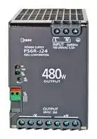


PS6R-J24
AC/DC DIN Rail Power Supply (PSU), ITE, 1 Output, 480 W, 24 VDC, 20 A
- Manufacturer: IDEC
- Product type:
- SVHC: No SVHC (15-Jan-2019)
- Product Range: PS6R Series
- No. of Outputs: 1 Output
- Output Power Max: 480W
- Current, Output 4: -
- Input Voltage VAC: 100V AC to 240V AC
- Power Supply Output Type: Adjustable, Fixed
- Output Current - Output 1: 20A
- Output Current - Output 2: -
- Output Current - Output 3: -
- Output Voltage - Output 1: 24VDC
- Output Voltage - Output 2: -
- Output Voltage - Output 3: -
- Output Voltage - Output 4: -
- Power Supply Applications: ITE
| Delivery and price | |
|---|---|
| Units per pack | 5 |
| Price | 307.77 € |
| Current stock | 10+ |
| Lead time | 30 days |
## **PS6R Series Switching Power Supplies** Expandable and space-saving switching power supplies. High efficiency reduces operation costs. - 93% efficiency - Plug-in output modules for additional output voltages - Plug-in branch terminal module for additional terminals - Power Range: 120W, 240W, 480W - Input voltage: 100 to 240V AC (voltage range: 85 to 264V AC/110 to 350V DC) - Up to 70ºC (158ºF) operating temperature - DC low LED indicator and output contact - The terminals are captive spring-up screws. Ring or fork terminals can be used. - Finger-safe construction prevents electric shocks. - Panel mount bracket and side-mount panel mounting bracket. Can be attached to a DIN rail or directly to a panel surface. - RoHS compliant |Applicable Standards<br>UL508<br>CSA C22.2 No. 107.1|Mark<br>**C**<br>**US**<br>**LISTED**|File No. or Organization<br>UL/c-UL Listed<br>File No. E177168| |---|---|---| |EN60950-1<br>EN50178<br>EN61204-3||TÜV SÜD| |||EU Low Voltage Directive<br>EMCD| **==> picture [187 x 8] intentionally omitted <==** **----- Start of picture text -----**<br> 37 mm 60mm 85mm<br>**----- End of picture text -----**<br> SEMI, ANSI (Hazardous location), and Maritime standards are pending. ## **Part Numbers** ## PS6R |PS6R||||| |---|---|---|---|---| |Output<br>Capacity*<br>120W|Part No.<br>**PS6R-F24**|Input Voltage<br>100 to 240V AC|Output<br>Voltage<br>21.6 to 26.4V|Output<br>Current<br>5A| |240W|**PS6R-G24**|||10A| |480W|**PS6R-J24**|||20A| *Output voltage × output current = output capacity ## Accessories |Accessories||| |---|---|---| |Item<br>Output Voltage Expansion<br>Module<br>Note 1|Part No.<br>PS9Z-6RM1|Note<br>Output: +5V, 2A, 10W| ||PS9Z-6RM2|Output: +12V, 1A, 12W| ||PS9Z-6RM3|Output: +5V, 1A/-5V, 1A, 10W| ||PS9Z-6RM4|Output: +15V, 0.4A/-15V, 0.4A, 12W| ||PS9Z-6RM5|Output: +5V, 1A/+12V, 0.5A, 11W| ||PS9Z-6RM6|Output: +12V, 0.5A/-12V, 0.5A, 12W| |Branch Terminal Module<br>Note 2|PS9Z-6RS1|Additional screw terminals for<br>wiring: 2 + terminals / 2 - terminals| |Panel Mounting Bracket|PS9Z-6R1F|| |Side-mount Panel Mounting<br>Bracket|PS9Z-6R2F|Supplied with M3 × 6 countersunk<br>mountingscrews| |DIN Rail|BNDN1000<br>~~|~~|1,000mm| |DIN Rail End Clip|BNL6<br>~~|~~|| 1. When using an output voltage expansion module, reduce 1A from the output current of PS6R. 2. When using a branch terminal module, the total voltage/current of PS6R and the branch terminal module should not exceed the rated current/voltage of PS6R 120W shown with Branch Terminal module attached. ## **Specifications** PS6R |Part No.|Part No.|Part No.|PS6R-F24|PS6R-G24|PS6R-J24| |---|---|---|---|---|---| |Input|Input Voltage<br>100 to 240V AC<br>(Voltage range: 85 to 264V AC/110 to 350V DC) (Load ≤ 80% at 85 to 100V AC, 110 to 140V DC)<br>Note 1||||| ||Frequency<br>50/60Hz||||| ||Input Current|100V AC<br>1.4A typ||2.7A typ|5.5A typ.| |||230V AC<br>0.7A typ||1.2A typ|2.3A typ.| ||Inrush<br>Current|100V AC<br>9A max. (Ta=25ºC, 100V AC cold start)|||| |||230V AC<br>20A max. (Ta=25ºC, 230V AC cold start)|||| ||Leakage<br>Current|120V AC<br>0.5mA max.|||| |||230V AC<br>1mA max.|||| ||Efficiency<br>(Typical)|100V AC<br>90%||90%|91%| |||230V AC<br>90%||91%|93%| ||Power Factor<br>(Typical)|100V AC<br>0.99||0.99|0.98| |||230V AC<br>0.96||0.97|0.97| |Output<br>~~IE~~|Rated Voltage/Current<br>24V/5A<br>24V/10A<br>24V/20A<br>~~IE~~||||| ||Adjustable Voltage Range<br>±10%<br>~~IE~~||||| ||Output HoldingTime<br>20ms min. (at rated input and output)<br>~~IE~~||||| ||Start Time<br>800ms max. (at rated input and output)<br>~~IE~~||||| ||Rise Time<br>200ms max. (at rated input and output)<br>~~IE~~||||| ||Regulation<br>~~IE~~|Total Fluctuation<br>±5% max.<br>~~IE~~|||| |||Input Fluctuation<br>0.4% max.<br>~~IE~~|||| |||Load Fluctuation<br>0.6% max.<br>~~IE~~|||| |||Temperature Change<br>0.05%/oC max. (–10 to +60ºC)<br>~~IE~~|||| |||Ripple (including noise)<br>1%p-pmax. (0 to +60ºC)<br>1.5%p-pmax. (–10 to 0ºC)<br>~~IE~~|||| |Supplementary<br>Functions<br>~~IE~~|Overcurrent Protection<br>105 to 120% (auto reset) (output current when voltage drops by 5%)<br>~~IE~~||||| ||Overvoltage Protection<br>Output off at 120%<br>Note 2<br>~~IE~~||||| ||Operation Indicator<br>LED (green)<br>~~IE~~||||| ||Voltage Low Indication<br>LED (amber)<br>~~IE~~||||| |Dielectric<br>Strength<br>~~IE~~|Between input and output terminals<br>3000V AC, 1 minute<br>~~IE~~||||| ||Between input andground terminals<br>2000V AC, 1 minute<br>~~IE~~||||| ||Between output andground terminals<br>500V AC, 1 minute<br>~~IE~~||||| **==> picture [100 x 197] intentionally omitted <==** **----- Start of picture text -----**<br> EMI<br>EMC<br>EMS<br>Degree of Protection<br>Weight (approx.)<br>Terminal Screw<br>2. One minute after the output has been turned off, turn on the input again.<br> Easily Expandable<br>e<br>**----- End of picture text -----**<br> 1. DC input voltage is not subjected to safety standards. 2. One minute after the output has been turned off, turn on the input again. 3. See the output derating curves. Branch Terminal Module Two terminals can be added. No wiring is required, reducing installation space. Output Voltage Expansion Module In addition to the standard 24V output, additional 5, 12, and 15V outputs can be added. Accessories (For use with PS6R) |Part No.<br>Output Voltage Expansion Module<br>Branch Terminal Module<br>PS9Z-6RM1<br>PS9Z-6RM2<br>PS9Z-6RM3<br>PS9Z-6RM4<br>PS9Z-6RM5<br>PS9Z-6RM6<br>PS9Z-6RS1<br>Input Voltage<br>24V DC<br>Output Capacity<br>10W max.<br>12W max.<br>10W max.<br>12W max.<br>11W max.<br>12W max.<br>—<br>Output<br>Rated Voltage/Current<br>5V/2A<br>12V/1A<br>±5V 2A<br>±15V 0.4A<br>5V/1A,<br>12V/0.5A<br>±12V 0.5A<br>24V/10A max.<br>Note 1<br>Adjustable Voltage Range<br>Not available<br>Voltage Accuracy<br>±5% max.<br>—<br>Start Time<br>200 ms max. (at rated input and output)<br>—<br>Regulation<br>Input Fluctuation<br>0.5% max.<br>—<br>Load Fluctuation<br>1.0% max.<br>Te m p e r a t u r e<br>Change<br>0.05%/max. (–10 to +60°C)<br>Ripple (including<br>noise)<br>100mV max.<br>150mV max.<br>100mV max., 150mV max.<br>Supplementary<br>Functions<br>Overcurrent Protection<br>105% (auto reset)<br>—<br>Overvoltage Protection<br>Output off at 120%<br>~~Bp~~<br>~~POPO~~<br>~~————~~<br>~~|sid~~<br>~~|~~<br>~~Cna~~<br>~~:~~<br>~~ee~~<br>~~ee~~| |---| |OperatingTemperature<br>–10 to +70°C (no freezing)<br>Note 2<br>~~PC~~| |OperatingHumidity<br>20 to 90%RH (no condensation)<br>Storage Temperature<br>–25 to +75°C (no freezing)<br>Storage Humidity<br>20 to 90% RH (no condensation)<br>Vibration Resistance<br>10 to 55 Hz, amplitude 0.375 mm, 2 hours each in 3 axes, 6 directions (in combination with PS6R-J24)<br>Shock Resistance<br>300 m/s<br>2(150 m/s<br>2when using a PS9Z-6R1F panel mounting bracket),<br>3 shocks each in 6 axes (in combination with PS6R-J24)<br>~~PO~~<br>~~—<~~| |EMC<br>EMI<br>EN61204-3 (Class B) (in combination with PS6R-24)<br>—<br>EMS<br>EN61204-3 (industrial) (in combination with PS6R-24)<br>~~—~~| |SafetyStandards<br>UL508 (Listing), CSA C22.2 No.107.1, IEC/EN60950-1, EN50178 (in combination with PS6R-24)<br>Degree of Protection<br>IP20 (IEC 60529)<br>Weight (approx.)<br>90g<br>30g<br>Terminal Screw<br>M3.5 (See lastpage for wire sizes.)<br>~~PO~~<br>~~—_~~<br>~~OO~~| 1. Ensure that the current does not exceed the rated current of the PS6R. 2. See the output derating curves. **==> picture [474 x 164] intentionally omitted <==** **----- Start of picture text -----**<br> Wide Operating Termperature Range | Energy-saving 93% Efficiency (480W)<br>96<br>100<br>90 94 PS6R-J24<br>80 Operates without derating 92 Competitor A<br>70 at 0 to 60ºC 90 Competitor B<br>60<br>88<br>50<br>40 86 REROF ateee<br>30 Operates at –10 to 70ºC 84 pibirTeibijebee<br>20<br>82<br>10<br>80 [bit]]<br>0 ae FaresPpt ESHA [fii][ ei][ Te] EELL [ biiT] pee [ bbe][ e] ESTES [ |] ited<br>–10 0 10 20 30 40 50 60 70 50 100 150 200 250 300<br>Input Voltage (V AC)<br>Operating Temperature (°C)<br>Efficiency (%)<br>Output Current (%)<br>**----- End of picture text -----**<br> ## **Wide Operating Termperature Range** ## **Easy Maintenance - LED Indicator** Overload or Input Output Output Status Normal Voltage Low* short-circuit OFF DC ON (green LED) ~~i] ele~~ DC Low (amber LED) ~~eo 8 8~~ *The LEDs turn on when the input voltage drops. ## **Dimensions (mm)** **==> picture [247 x 135] intentionally omitted <==** **----- Start of picture text -----**<br> PS6R-F24 PS6R-G24<br>6 - M3.5 8 - M3.5<br>Terminal Screws Terminal Screws<br>ttl A A ___ 125 dd 4 tr A A<br>8 ) ® | [ 8 )<br>a a . ~<br>(za) 37 A = 9.5 3.8 (essea] A A A A A<br>a im penaal 60 A = 9.5<br>9.3 9.3<br>44.9<br>106.5 35.3 125 106.5<br>4.5<br>**----- End of picture text -----**<br> **==> picture [258 x 135] intentionally omitted <==** **----- Start of picture text -----**<br> PS6R-J24<br>10-M3.5<br>Terminal Screws<br>125 4 A A 125 4<br>rr a<br>i ( 8 D ® H |<br>. Lr a . .<br>3.8 [| | fessseza| A A A A A A 3.8 |<br>85 A = 9.5<br>it LLL<br>9.3<br>44.9 44.9<br>35.3 125 106.5 35.3 125<br>4.5<br>4.5<br>**----- End of picture text -----**<br> PS9Z-6R1F Panel Mounting Bracket **==> picture [115 x 7] intentionally omitted <==** **----- Start of picture text -----**<br> When a PS9Z-6R1F is installed on PS6R<br>**----- End of picture text -----**<br> **==> picture [226 x 150] intentionally omitted <==** **----- Start of picture text -----**<br> A A 130.6<br>0.. —_— ® |<br>Leet}<br>(Front view) (Side view)<br>10<br>145<br>10<br>**----- End of picture text -----**<br> **==> picture [529 x 446] intentionally omitted <==** **----- Start of picture text -----**<br> 28 4-M4 or ø4-4.5 holes<br>——) | | 0.. —_— ® |<br>of 28 tb $—- 28 4 Panel cut-out Leet} (Front view) (Side view)<br>39<br>Tommal<br>PS9Z-6R2F When a PS9Z-6R2F is installed on PS6R<br>Side-mount Panel Mounting Bracket 4-M4 or 4-94.5 holes<br>56 4-M4 or ø4-4.5 holes<br>| | .--ooo> = “7-1 =|ne pe<br>8 lg Ls<br>| | | I! Ie<br>° ° | il ly<br>: | | ( ESSSESS | eel<br>| __. 7056 , $-—- 56 -4 Panel cut-out (Front view) SEEIRI gt~ gMoun t ing Screws<br>(Side view) (M36 × countersunk screw)<br>When using a PS9Z-6RM* When using a PS9Z-6RS1<br>Output Voltage Expansion Module Branch Terminal Module<br>Dimension Table<br>LT oe 5 | Tess)! A B C D E<br>oy Pf oi !<br>PS6R-F24 – 39.3 29.5 29.5 58<br>H | H | li ¢ it PS6R-G24 10.5 62.3 29.5 31 81<br>ieeot |i | os CoH0 6 8 )F PS6R-J24 | 23 | 87.3 [ 29.5 | 31 | 106<br>10<br>145<br>135 145<br>135<br>10<br>138.5 148.6 138.5<br>**----- End of picture text -----**<br> PS9Z-6R2F Side-mount Panel Mounting Bracket ## **Parts Description** **==> picture [28 x 7] intentionally omitted <==** **----- Start of picture text -----**<br> PS6R-J24<br>**----- End of picture text -----**<br> **==> picture [295 x 21] intentionally omitted <==** **----- Start of picture text -----**<br> PS6R-6RM1/M2/M3 PS9Z-6RM3/M4/M6 PS6R-6RS1<br>Output Voltage Expansion Module Output Voltage Expansion Module Branch Terminal Module<br>**----- End of picture text -----**<br> (PS6R-6RM5 shown) ## PS6R- 24/PS9Z-6RS1 |Marking<br>L, N|Name<br>Input Terminal|Description<br>Voltage range: 85 to 264V AC/110 to 350V DC| |---|---|---| ||Ground Terminal|Be sure to connect this terminal to a proper ground.| |+V, –V|DC Output Terminals|+V: Positive output terminal<br>–V: Negative output terminal| |VR.ADJ|Output Voltage Adjustment|Allows adjustment within ±10%. Turning clockwise increases the output voltage.| |DC ON|Operation Indicator (green)|Lights on when the output voltage is on.| |DC LOW|Output Low Indicator (Amber)|Lights on when the output voltage drops approximately 80% of the rated value.| |DC OK|DC OK Output|Lights on when the output voltage is more than 80% of the rated value.<br>NPN transistor output (50V DC max., 50 mA max.)| ## PS9Z-6RM |Marking<br>Name<br>+5V, +12V, +15V<br>DC Output Terminal|Name<br>DC Output Terminal|Description<br>+5V side, +12V side, +15V side| |---|---|---| |-5V, -12V, -15V<br>DC Output Terminal|DC Output Terminal|-5V side, -12V side, -15V side| |COM<br>DC Output Terminal|DC Output Terminal|0V side (wired internally to –V of PR6R-J24)| ## **Characteristics** Operating Temperature vs. Output Current (Derating Curves) **==> picture [504 x 125] intentionally omitted <==** **----- Start of picture text -----**<br> Operating Temperature vs. Output Current vs. Input Voltage Overcurrent Protection Characteristics Overcurrent Protection<br>Output Current (Derating Curves) (Derating Curves) (Ta=25ºC) PS6R- 24 Characteristics PS9Z-6RM*<br>105% 120%<br>100 100 100 \ f 95% 10090<br>90 90 80<br>8070 8070 F24 7060<br>50<br>60 60 G24 40<br>50 50 30<br>40 40 J24 20<br>30 30 10<br>20 20 (ACV)0 85 100 264<br>10 10 Pulse Current (DCV) 110 140 Input Voltage(V) 350<br>(Approx. 30A rms, 40A peak)<br>0 0 0<br>–10 0 10 20 30 40 50 60 70 (ACV) 85 100 264 0 100<br>Operating Temperature (ºC) (DCV) 110 140 Input Voltage(V) 350 Input Current (%)<br>Output Voltage (%) Output Current (%)<br>Output Current (%) Output Current (%)<br>**----- End of picture text -----**<br> ## **Operating Temperature approved by Safety Standards** |Part No.<br>UL508, CSA C22.2 No. 107. 1|UL508, CSA C22.2 No. 107. 1| |---|---| |PS6R-F24|60ºC| |PS6R-G24|60ºC| |PS6R-J24|55ºC| |PS9Z-6R|55ºC| ## **Operating Instructions** The PS6R should be placed in a proper enclosure. It is designed to be used with general electrical equipment and industrial electric devices. ## Operation Notes 1. Output interruption may indicate blown fuses. Contact IDEC. 2. The PS6R contains an internal fuse for AC input. When using DC input, install an external fuse or DC input. To avoid blown fuses, select a fuse in consideration of the rated current of the internal fuse. ## Rated Current of Internal Fuses |Part No.<br>PS6R-F24|Internal Fuse Rated Current<br>4A| |---|---| |PS6R-G24|6.3A| |PS6R-J24|10A| - Avoid overload and short-circuit for a long period of time, otherwise internal elements may be damaged. - DC input operation is not subjected to safety standards. ## Installation Notes • The PS6R can be installed in the direction shown below only. Up 4p ~~. |~~ Vertical When using PS9Z-6R1F When using PS9Z-6R2F Panel Mounting Bracket Side-mount Panel Mounting Bracket - Do not close the top and bottom openings of the PS6R to allow for heat radiation by convection. - Maintain a minimum of 20mm clearance around the PS6R, except for the top and bottom openings. - When derating of the output does not work, provide forced air-cooling. - Make sure to wire the ground terminal correctly. - For wiring, use wires with heat resistance of 60ºC or higher. - Use copper wire of the following sizes. Wires of the following sizes must be used to comply with UL508, CSA C22.2 No. 107.1. |Model|Terminal|Wire Size/No. of Wire|Wire Type<br>Torque,<br>in-ibs (N∙m)|Torque,<br>in-ibs (N∙m)| |---|---|---|---|---| |PS6R-F24<br>PS6R-G24|PS6R-F24<br>PS6R-G24<br>Input<br>18-14 AWG, 1-wire<br>Output<br>18-14 AWG, 1-wire, (18 AWG - 7A,<br>16 AWG - 10A, 14 AWG - 15A)<br>DC OK<br>Output<br>22-14 AWG, 1-wire (stripped wire<br>length: 6 to 7mm)|18-14 AWG, 1-wire|Copper<br>Solid/Stranded<br>7.0 (0.8)<br>Copper<br>Solid/Stranded<br>Use with UL-listed ring/<br>fork crimp terminal.|7.0 (0.8)| |||18-14 AWG, 1-wire, (18 AWG - 7A,<br>16 AWG - 10A, 14 AWG - 15A)||| |||22-14 AWG, 1-wire (stripped wire<br>length: 6 to 7mm)||| |PS6R-J24|PS6R-J24<br>Input<br>18-14 AWG, 1-wire<br>Output<br>18-14 AWG, 2-wire<br>Use the same size wire for each<br>terminal (18 AWG - 7A,<br>16 AWG - 10A, 14 AWG - 15A)<br>12 AWG, 1-wire<br>DC OK<br>Output<br>22-14 AWG, 1-wire (stripped wire<br>length: 6 to 7mm)|18-14 AWG, 1-wire||| |||18-14 AWG, 2-wire<br>Use the same size wire for each<br>terminal (18 AWG - 7A,<br>16 AWG - 10A, 14 AWG - 15A)||| |||12 AWG, 1-wire||| |||22-14 AWG, 1-wire (stripped wire<br>length: 6 to 7mm)|Copper<br>Solid/Stranded<br>—<br>7.0 (0.8)|—| |PS9Z-6R0|0 Output<br>18-14 AWG, 1-wire (18 AWG - 7A,<br>16 AWG -10A, 14 AWG - 15A)|18-14 AWG, 1-wire (18 AWG - 7A,<br>16 AWG -10A, 14 AWG - 15A)||7.0 (0.8)| ## Applicable Crimp Terminal (reference) ø3.6 min. 6.6 max. 4 max. 5.5 min. aS cae • Recommended tightening torque of the input and output terminals is 0.8N·m. - The output voltage can be adjusted within ±10% of the rated output voltage by using the V.ADJ control. Note that overvoltage protection may work when increasing the output voltage. - When large shocks or heavy vibrations on the PS6R are expected, the use of DIN rail or PS9Z-6R2F side-mount panel mounting bracket is recommended. ## Series Operation The following series operation is allowed. Connect Schottky barrier diodes as shown below. Output voltage expansion modules cannot be connected in series. **==> picture [157 x 59] intentionally omitted <==** **----- Start of picture text -----**<br> L L +V L L +V<br>N N –V Load N N –V<br>Load<br>L +V Load L +V<br>N –V N –V<br>=<br>(a) (b)<br>**----- End of picture text -----**<br> Select a Schottky diode in consideration of the rated current. The diode’s reverse voltage must be higher than the PS6R’s output voltage. ## Parallel Operation Parallel operation is possible to increase the output capacity. Output voltage expansion modules cannot be connected in series. **==> picture [75 x 41] intentionally omitted <==** **----- Start of picture text -----**<br> L L +V<br>Load<br>N N –V<br>L +V<br>N –V<br>**----- End of picture text -----**<br> When increasing the capacity, observe the following. 1. Maintain the operating temperature below 40ºC. 2. Output cannot be connected directly in parallel operation. Connect a diode to the output of each PS6R. 3. Output terminal voltage of both power supplies must be the same. Also, maintain the voltage difference between the power supplies below 30mV. 4. Use load lines of the same diameter and length. 5. Set the output voltage higher for the amount of diode forward voltage drop. 6. Turn on the inputs at the same time. 7. Select a diode in consideration of: - Diode’s reverse voltage must be higher than the PS6R’s output voltage. Diode’s current must be three times the PS6R’s output current. Provide a heat sink for heat dissipation. IDEC Corporation • 1175 Elko Drive • Sunnyvale, CA 94089 • 800-262-IDEC (4332) • Fax: 408-745-5258 • www.IDEC.com/usa ©2013 IDEC Corporation. All Rights Reserved. PS9Y-DS400-0 _11/13 5K_
Updated at June 4, 2026
Founded in 1945, IDEC is a globally recognized leader in industrial automation, machine safety, and control products. Renowned for pioneering innovations in Human-Machine Interface (HMI) systems, the company is dedicated to creating a safe and efficient harmony between advanced workplace technology and human operators. At the core of IDEC’s extensive portfolio is a comprehensive selection of high-performance relays designed for demanding industrial environments. This includes a broad range of electromechanical power relays, solid-state relays, contactors, and critical safety relays, supported by a wide array of specialized relay accessories to ensure reliable and efficient switching. Beyond switching components, IDEC provides complete solutions for modern control panels and automated systems. Their robust engineering extends to advanced panel displays and instrumentation, precision light sensors, and dependable AC/DC power converters. With additional offerings in industrial switches, visual signaling units, and DIN rail terminal blocks, IDEC equips engineers with the high-quality components required to build secure, next-generation automation infrastructure.
About Novapart
Novapart is a B2B electronic component broker specialising in stock shortages and cost reduction. We source hard-to-find parts and identify compliant alternatives across a catalogue of 410,000+ components from 500+ manufacturers.
Learn more →Stock Shortage Specialist
When a component is unavailable, discontinued or has an unacceptable lead time, we tap into our network of vetted European and Asian distributors to source what you need — without compromising on quality or traceability.
Request a quote →Compliant Alternatives
We identify pin-to-pin, electrically equivalent substitutes that meet the same certifications (RoHS, AEC-Q100, REACH) as your original specification — validated against datasheets, not just part numbers. Often at a lower cost.
BOM Analysis service →