
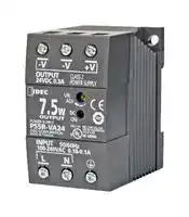


PS5R-VA12
AC/DC DIN Rail Power Supply (PSU), ITE & Industrial, 1 Output, 7.5 W, 12 V, 600 mA
- Manufacturer: IDEC
- Product type:
- SVHC: No SVHC (25-Jun-2025)
- Product Range: PS5R-V Series
- No. of Outputs: 1 Output
- Output Power Max: 7.5W
- Current, Output 4: -
- Input Voltage VAC: 85V AC to 264V AC
- Power Supply Output Type: Fixed
- Output Current - Output 1: 600mA
- Output Current - Output 2: -
- Output Current - Output 3: -
- Output Voltage - Output 1: 12V
- Output Voltage - Output 2: -
- Output Voltage - Output 3: -
- Output Voltage - Output 4: -
- Power Supply Applications: ITE & Industrial
| Delivery and price | |
|---|---|
| Units per pack | 50 |
| Price | 36.54 € |
| Current stock | 10+ |
| Lead time | 30 days |
## Switching Power Supplies PS5R-V Series ## **PRODUCT DESCRIPTION** DIN-rail mount switching power supplies with global approvals for both industrial and hazardous locations ## **KEY FEATURES** - Compact size preserves panel space ## **STANDARDS COMPLIANCE** |Applicable Standards|Mark|File No. or Organization| |---|---|---| |UL508<br>UL13101<br>ANSI/ISA 12.12.01<br>CSA C22.2 No.107.1<br>CSA C22.2 No.213<br>CSA C22.2 No.2231||UL/c-UL Listed<br>File No. E467154, E177168| |EN60950-1<br>EN50178<br>EN61204-3<br>EN50581||TÜV SÜD²| |||EU Low Voltage Directive,<br>EMC Directive<br>RoHS Directive| |SEMI F47|—|EPRI| Note 1: PS5R-VA/VB/VC/VD/VE only Note 2: EN60950-1, EN50178 only ## **PART NUMBERS** |Output Capacity|Part Number|Input Voltage|Output Voltage|Output Current| |---|---|---|---|---| |7.5W|PS5R-VA05|100 to 240V AC<br>(Voltage range: 85 to 264V<br>AC /<br>100 to 370V DC)|5V|1.5A| ||PS5R-VA12||12V|0.6A| ||PS5R-VA24||24V|0.3A| |10W|PS5R-VB05||5V|2.0A| |15W|PS5R-VB12||12V|1.3A| ||PS5R-VB24||24V|0.65A| |30W|PS5R-VC12||12V|2.5A| ||PS5R-VC24||24V|1.3A| |60W|PS5R-VD24||24V|2.5A| |90W|PS5R-VE24||24V|3.75A| |120W|PS5R-VF24||24V|5.0A| |240W|PS5R-VG24||24V|10.0A| - Slim size (width): 22.5mm (10W/15W/30W) 36mm (60W/90W) 46mm (120W) 60mm (240W) - Universal Voltage Input: - 85-264V AC/100-370V DC - Wide operating temperature range - Spring-up terminals accept ring & fork terminals - Approved for use in Class I Division 2 hazardous locations - Can be installed in 6 directions - 10W ~ 90W meet NEC Class 2 output ratings - Overcurrent protection with auto-reset - Meets SEMI F47 Sag Immunity (208V AC input) - RoHS compliant - Five-year factory warranty ## **Part Number Structure** ## **PS5R - V** Output Capacity Output Voltage A: 7.5W 05: 5V[3] B: 10W/15W 12: 12V[4] C: 30W 24: 24V D: 60W E: 90W F: 120W Note 3: PS5R-VA/VB only G: 240W Note 4: PS5R-VA/VB/VC only Use only for interpreting part numbers. Do not use for developing part numbers. 1 ## **SPECIFICATIONS** **==> picture [575 x 672] intentionally omitted <==** **----- Start of picture text -----**<br> 5V DC output PS5R-VA05 PS5R-VB05 - - - - -<br>Model 12V DC output PS5R-VA12 PS5R-VB12 PS5R-VC12 - - - -<br>24V DC output PS5R-VA24 PS5R-VB24 PS5R-VC24 PS5R-VD24 PS5R-VE24 PS5R-VF24 PS5R-VG24<br>Output Capacity 7.5W 15W (5V Model is 10W) 30W 60W 90W 120W 240W<br>Rated Input Voltage 100 to 240V AC<br>(Single-phase two-wire) [1] (Voltage range: 85 to 264V AC/100 to 370V DC) (Load ≤ 80% at 100-105V DC)<br>Frequency 50/60 Hz<br> 5V: 0.25A<br>Input Current (Typ.) 100V AC 5V: 0.20A 12V, 24V: 0.18A 12V, 24V: 0.35A 0.7A 1.3A 1.1A 1.4A 2.7A<br> 5V: 0.14A<br>230V AC 5V: 0.12A 12V, 24V: 0.10A 12V, 24V: 0.19A 0.3A 0.8A 0.6A 0.7A 1.2A<br>Inrush Current (Typ.) 100V AC 15A 18A 14A<br>(Ta=25°C, cold start) 230V AC 36A 45A 41A 30A<br>120V AC 0.5mA max.<br>Leakage Current<br>230V AC 1.0mA max.<br>Efficiency (Typ.) 100V AC 5V: 74%, 12V: 79%, 24V: 80% 5V: 77%, 12V: 82%, 24V: 84% 12V: 83%, 24V: 85% 86% 88% 89%<br>(at rated output) [2] 230V AC 5V: 73%, 12V: 77%, 24V: 76% 5V: 73%, 12V: 80%, 24V: 81% 12V: 85%, 24V: 87% 86% 89% 90%<br>100V AC — — — — 0.99<br>Power Factor (Typ.) 230V AC — — — — 0.86 0.92 0.96<br>Rated Voltage/Current 5V/1.5A, 12V/0.6A, 24V/0.3A 5V/2.0A [3] , 12V/1.3A, 24V/0.65A 12V/2.5A, 24V/1.3A 24V/2.5A 24V/3.75A 24V/5A 24V/10A<br>Adjustable Voltage Range ±10% ±5% ±10%<br>100V AC 45ms 5V: 53ms, 12V: 34ms, 24V: 36ms 12V: 13ms, 24V: 15ms 13ms 20ms 30ms<br>Output Holding Time<br>(Typ.) (at rated output) 230V AC 285ms 5V: 330ms 12V: 215ms 24V: 230ms 12V: 110ms 24V: 110ms 105ms 30ms 33ms 40ms<br>Start Time (at rated input and output) 500ms max. 500ms max. 600ms max. 800ms max. 700ms max. 800ms max.<br>Rise Time (at rated input and output) 5V, 12V: 200ms max24V: 250ms max 5V, 12V: 200ms max. 24V: 250ms max. 200ms max.<br>Input Fluctuation 0.4% max.<br>Load Fluctuation 5V: 2.5% max. 12V, 24V: 1.0% max. 1.0% max.<br>0.04%/°C max. (-10 to 12V: 0.05%/°C max. (-10 to +50°C) 0.05%/°C max. 0.05%/°C max. 0.05%/°C max. 0.05%/°C max.<br>Temperature Change +65°C ) 0.05%/°C max. (-10 to +65°C ) 24V: 0.05%/°C max. (-10 to +55°C) (-10 to +55°C ) (-10 to +50°C ) (-25 to +55°C ) (-25 to +50°C)<br>12V: 6% p-p max. (-25 to -10°C)24V: 4% p-p max. (-25 to -10°C)5V: 8% p-p max. (-25 to -10°C) 12V:24V:5V: 8% p-p max. (-25 to -10°C)6% p-p max. (-25 to -10°C)4% p-p max. (-25 to -10°C) 12V:24V: 6% p-p max. (-25 to -10°C)4% p-p max. (-25 to -10°C) 4% p-p max. (-25 to -10°C)<br>Ripple (including noise) 12V: 2.5% p-p max. (-10 to +0°C)24V: 1.5% p-p max. (-10 to +0°C)5V: 5% p-p max. (-10 to +0°C) 12V: 2.5% p-p max. (-10 to +0°C)24V: 1.5% p-p max. (-10 to +0°C) 5V: 5% p-p max. (-10 to +0°C) 12V:24V: 2.5% p-p max. (-10 to +0°C)1.5% p-p max. (-10 to +0°C) 1.5% p-p max. (-10 to +0°C)<br>5V: 2.5% p-p max. (0 to +65°C) 5V: 2.5% p-p max. (0 to +65°C) 12V: 1.5% p-p max. (0 to +50°C) 1% p-p max. (0 to 1% p-p max. (0 to 1% p-p max. (0 to<br>12V: 1.5% p-p max. (0 to +65°C) 12V: 1.5% p-p max. (0 to +65°C) 24V: 1% p-p max. (0 to +55°C) +55°C) +50°C) 1% p-p max. (0 to +55°C) +50°C)<br>24V: 1% p-p max. (0 to +65°C) 24V: 1% p-p max. (0 to +65°C)<br>Overcurrent Protection 105% min. (auto reset) 101% min. (auto reset) 105% min. (auto reset)<br>Operation Indicator LED (green)<br>Between input and output terminals 3,000V AC, 1 minute<br>Between input and ground terminals 2,000V AC, 1 minute<br>Between output and ground terminals 500V AC, 1 minute<br>Insulation Resistance Between input and output terminals: 100MΩ min. (500V DC megger) Between input and ground terminals: 100MΩ min. (500V DC megger)<br>Operating Temperature [4] (No freezing) -25 to +75°C -25 to +70°C -25 to +65°C<br>Operating Humidity (no condensation) 20 to 90% RH<br>Storage Temperature (No freezing) -25 to +75°C<br>Storage Humidity (no condensation) 20 to 90% RH<br>10 to 55Hz, amplitude 0.21mm, 2<br>10 to 55Hz, amplitude 0.33mm, 2 hours each in 3 axes hours each in 3 axes 0.375mm, 2 hours each10 to 55 Hz, amplitude<br>Vibration Resistance 10 to 55Hz, amplitude 0.375mm, 2 hours each in 3 axes (when used with BNL6 end clips) (when used with BNL6 end clips) in 3 axes<br>(when used with BNL6 end clips) 10 to 55Hz, amplitude 0.375mm, 2 hours each in 3 axes (when used with BNL8 end clips) hours each in 3 axes (when used with 10 to 55Hz, amplitude 0.375mm, 2 (when used with part no.<br>BNL8 end clips) BNL6 mounting clips)<br>Shock Resistance 300 m/s [2] (30G), 3 times each in 6 directions<br>Expected Life [5] 8 years minimum (at the rated input, 50% load, operating temperature +40°C, standard mounting direction)<br>EMI EN61204-3 (Class B)<br>EMC<br>EMS EN61204-3 (industrial)<br>Safety Standards UL508 (Listing), UL1310 Class 2, ANSI/ISA-12.12.01CSA C22.2 No. 107.1, 213, 223 EN60950-1, EN50178 CSA C22.2 No. 107.1, 213 EN60950-1, EN50178 UL508 (Listing) ANSI/ISA-12.12.01<br>Other Standard SEMI F47 (at 208V AC input only)<br>Degree of Protection IP20 (EN60529)<br>Dimensions (mm) 75H × 45W × 70D 90H × 22.5W × 95D 95H × 36W × 108D 115H × 46W × 121D 125H × 60W × 125D<br>Weight (approx.) 130g 140g 150g 260g 310g 470g 960g<br>Terminal Screw M3.5<br>Input<br>Output<br>Regulation<br>Dielectric Strength<br>**----- End of picture text -----**<br> *At normal temperature and humidity unless otherwise specified. Note 1: DC input voltage is not subject to safety standards. When using on DC input, connect a fuse to the input terminal for DC input protection. Note 2: Under stable state. Note 3: PS5R-VB05 (5V DC/2.0A) is 10W (Up to 3.0A at Ta = 0 to 40°C. Not subject to safety standards above 2.0A.) Note 4: See the output derating curves. Note 5: Calculation of the expected life is based on the actual life of the aluminum electrolytic capacitor. The expected life depends on operating conditions. 2 ## **CHARACTERISTICS** ## **Operating Temperature vs. Output Current (Derating Curves)** Conditions: Natural air cooling (Operating temperature is the temperature around the switching power supply.) ## **PS5R-VA05, -VA12, -VA24** ## **PS5R-VB05, -VB12, -VB24** ## **PS5R-VC12** **==> picture [536 x 696] intentionally omitted <==** **----- Start of picture text -----**<br> 100 Mounting A,E 100 Mounting A 100 Mounting A<br>90 90 90<br>80 80 Input Voltage: 80 Input Voltage:<br>70 70 85-100V AC 70 85-100V AC<br>60 60 60<br>50 50 50<br>40 40 40<br>30 Mounting B, C, D, F 30 Mounting B, C, D, E, F 30<br>20 20 20 Mounting B, C, D, E, F<br>10 10 10<br>0 0 0<br>-30 -20 -10 0 10 20 30 40 50 60 70 80 -30 -20 -10 0 10 20 30 40 50 60 70 80 -30 -20 -10 0 10 20 30 40 50 60 70 80<br>Operating Temperature (˚C) Operating Temperature (˚C) Operating Temperature (˚C)<br>PS5R-VC24 PS5R-VD24 PS5R-VE24<br>10090 Mounting A, B 10090 Mounting E 10090 Mounting A<br>8070 Input Voltage: 85-100V AC 8070 Input Voltage: 85-100V AC 8070 Mounting E<br>60 60 Mounting B, C, D 60<br>5040 Mounting C 5040 5040<br>30 30 Mounting A 30 Mounting<br>20 Mounting D, E, F 20 Mounting F 20 B, C, D, F<br>10 10<br>10<br>0 0<br>-30 -20 -10 0 10 20 30 40 50 60 70 80 -30 -20 -10 0 10 20 30 40 50 60 70 80 0<br>Operating Temperature (˚C) Operating Temperature (˚C) -30 -20Operating Temperature (-10 0 10 20 30 40 50 ˚C)60 70 80<br>PS5R-VF24 PS5R-VG24<br>100 100 Mounting A<br>9080 Mounting C, E 9080 Mounting E<br>7060 Mounting B, D 7060 Mounting B<br>50<br>50<br>40<br>40<br>30<br>20 Mounting F Mounting A 30 Mounting<br>10 20 C, D, F<br>0 10<br>-30 -20 -10 0 10 20 30 40 50 60 70 80 0<br>Operating Temperature (˚C) -30 -20 -10 0 10 20 30 40 50 60 70 80<br>Operating Temperature (˚C)<br>Input Voltage vs. Output Current (Derating Curves) Ta=25°C<br>PS5R-VB05, -VB12, -VB24, -VC12, -VC24, -VD24, PS5R-VA05, -VA12, -VA24, -VG24<br>-VE24, -VF24<br>100 100<br>90 90 AC<br>80 80<br>70 70 DC<br>60 60<br>50 50<br>40 40<br>30 30<br>20 20<br>10 10<br>(ACV)085 f 100 T 264 0<br>(DCV) 100 140 Input Voltage (V) 370 (ACV)(DCV)10085 100105 Input voltage (V) 264370<br>Overcurrent Protection Characteristics<br>PS5R-VA/VB/VC/VD/VF PS5R-VE24 PS5R-VG24<br>100 100<br>100 95<br>95<br>Intermittent Operation<br>Intermittent Operation<br>0<br>0 0 0 100<br>-30 0 100 105 and over 0 Output Current (%) 100 Output Current (%) 105 and over<br>Output Current (%) 101 and over<br>0 iat lem<br>3<br>Output Current (%) Output Current (%) Output Current (%)<br>Output Current (%) Output Current (%) Output Current (%)<br>Output Current (%)<br>Output Current (%)<br>Output Current (%) (%)<br>Output Current<br>Output Voltage (%) Output Voltage (%)<br>Intermittent Operation Output Voltage (%)<br>**----- End of picture text -----**<br> ## **Operating Temperature Approved by Safety Standards** **==> picture [392 x 151] intentionally omitted <==** **----- Start of picture text -----**<br> UL508, CSA C22.2 No.107.1, ANSI/ISA12.12.01, EN60950-1, EN50178<br>Part Number<br>Mounting A Mounting B Mounting C Mounting D Mounting E Mounting F<br>PS5R-VA05, -VA12, -VA24 65 60 60 60 65 60<br>PS5R-VB05, -VB12, -VB24 65 60 60 60 60 60<br>PS5R-VC12 50 45 45 45 45 45<br>PS5R-VC24 55 55 50 45 45 45<br>PS5R-VD24 55 40 40 40 45 35<br>PS5R-VE24 50 40 40 40 45 40<br>PS5R-VF24 55 40 45 40 45 35<br>PS5R-VG24 50 35 30 30 45 30<br>**----- End of picture text -----**<br> ## **MOUNTING STYLE** **==> picture [425 x 75] intentionally omitted <==** **----- Start of picture text -----**<br> Up<br>Mounting A Mounting B Mounting C Mounting D Mounting E Mounting F<br>(Vertical, standard) (Upright) (Right side up) (Left side up) (Upside down) (Downward)<br>**----- End of picture text -----**<br> **Front Panel PS5R-VA PS5R-VB/VC PS5R-VD/VE/VF PS5R-VG** **==> picture [107 x 130] intentionally omitted <==** **----- Start of picture text -----**<br> INP UT<br>L N<br>INPUT 50/60Hz<br>100 -240 VAC<br>DC ON<br>ON VR.<br>VR.ADJ ADJ<br>OUTPUT<br>-V +V<br>OUTP UT<br>**----- End of picture text -----**<br> **==> picture [55 x 91] intentionally omitted <==** **==> picture [276 x 124] intentionally omitted <==** **----- Start of picture text -----**<br> Marking Name Description<br>L, N AC Input Terminal Voltage range: 85 to 264V AC/100 to 370V DC<br>Ground Terminal Be sure to connect this terminal to a proper<br>ground.<br>+V: Positive output terminal<br>+V, -V DC Output Terminals -V: Negative output terminal<br>Allows adjustment within ±10%. (VE = ±5%)<br>VR.ADJ Output Voltage Adjustment Turning clockwise increases the output voltage.<br>Turning counterclockwise decreases the output<br>voltage.<br>DC ON Operation Indicator (green) Illuminates when the output voltage is on.<br>**----- End of picture text -----**<br> ## **ACCESSORIES Panel Mounting Bracket[2]** **==> picture [279 x 100] intentionally omitted <==** **----- Start of picture text -----**<br> Applicable Switching Power Supply Part Number Remarks<br>PS5R-VB PS9Z-5R1B —<br>PS5R-VC PS9Z-5R2B For side mounting<br>PS5R-VDPS5R-VE PS9Z-5R1C —<br>PS5R-VF PS9Z-5R1E —<br>PS9Z-6R1F —<br>PS5R-VG<br>PS9Z-6R2F For side mounting<br>**----- End of picture text -----**<br> Note 2: Used when installing on a panel directly, PS5R-VA model does not require panel mounting bracket. ## **DIN Rail (35mm-wide)** **==> picture [236 x 30] intentionally omitted <==** **----- Start of picture text -----**<br> Length Part Number Material<br>1000mm BNDN1000 Aluminum<br>**----- End of picture text -----**<br> **End Clip** Part Number BNL6 BNL8 4 **DIMENSIONS (MM) PS5R-VA** ## **PS5R-VB/VC** **==> picture [205 x 137] intentionally omitted <==** **----- Start of picture text -----**<br> 6-M3.5 70<br>Screw Terminal 6<br>26 3.8<br>35<br>38.5<br>45<br>19.9<br>62.5 60 75 35.3<br>5<br>7.35<br>**----- End of picture text -----**<br> ## **PS5R-VD/VE** **==> picture [223 x 135] intentionally omitted <==** **----- Start of picture text -----**<br> 10 10 5-M3.5<br>Screw Terminal 108<br>20<br>3.8<br>36<br>8<br>24.9<br>97 95 35.3<br>4.5<br>**----- End of picture text -----**<br> ## **PS5R-VG** **==> picture [268 x 169] intentionally omitted <==** **----- Start of picture text -----**<br> 8-M3.5Screw Terminal 9.5 9.5 125 5.5<br>9.5 9.5 9.5 9.5 3.8<br>60<br>9.3<br>44 .9<br>10 6.5 35 .3 12 5<br>4.5<br>**----- End of picture text -----**<br> **==> picture [214 x 137] intentionally omitted <==** **----- Start of picture text -----**<br> 5-M3.5<br>Screw Terminal 95<br>9.5<br>3.8<br>22.5<br>8.2<br>12.2 27.3<br>90 35.3<br>61.6<br>4.4<br>**----- End of picture text -----**<br> ## **PS5R-VF** **==> picture [246 x 350] intentionally omitted <==** **----- Start of picture text -----**<br> 5-M3.5<br>Screw Terminal<br>11.5 11.5 121<br>23<br>3.8<br>46<br>MTBF*<br>PS5R-VA: 1,150,000H minimum<br>PS5R-VB: 900,000H minimum<br>PS5R-VC: 650,000H minimum<br>MIL-HDBK-217FN2<br>PS5R-VD: 450,000H minimum<br>(GB, 30°C)<br>PS5R-VE: 380,000H minimum<br>PS5R-VF: 350,000H minimum<br>PS5R-VG: 290,000H minimum<br>*MTBF stands for Mean Time Between Failure, which is calculated according to<br>statistical device failures, and indicates reliability of a device. It is the statistical<br>representation of the likelihood of the unit to fail and does not necessarily repre-<br>sent the expected life of a product.<br>85.<br>44.9<br>98 511<br>35.3<br>4.5<br>**----- End of picture text -----**<br> 5 **When installed on switching power supply** ## **Panel Mounting Bracket** **==> picture [207 x 697] intentionally omitted <==** **----- Start of picture text -----**<br> PS9Z-5R1B 2-M4 or 2- ø 4.5 holes<br>Mounting hole layout<br>when installing on<br>a panel directly<br>12 12<br>24.7<br>PS9Z-5R2B Side-mount 2-M4 or 2- ø 4.5 holes<br>Mounting hole layout<br>when installing on<br>a panel directly<br>44<br>62.9<br>PS9Z-5R1C 2-M4 or 2- ø 4.5 holes<br>Mounting hole layout<br>when installing on<br>26 26 a panel directly<br>38<br>PS9Z-5R1E<br>2-M4 or 2- ø 4.5 holes<br>Mounting hole layout<br>when installing on<br>36 36 a panel directly<br>48<br>PS9Z-6R1F<br>28 4-M4 or 4- ø 4.5 holes<br>Mounting hole layout<br>when installing on<br>a panel directly<br>28 28<br>39<br>PS9Z-6R2F Side-mount<br>56 4-M4 or 4- ø 4.5 holes<br>Mounting hole<br>layout for side<br>mounting<br>56 56<br>70<br>120 112 112<br>110 102.0 102<br>115 105 105<br>135 125 125<br>145 135 135<br>148.6 138.6 6381.<br>**----- End of picture text -----**<br> **==> picture [253 x 712] intentionally omitted <==** **----- Start of picture text -----**<br> 96.7<br>Front View Side View<br>28.8 5.5<br>Side View Front View<br>109.8<br>Front View Side View<br>122.8<br>Front View Side View<br>10.5 10.5 130.6<br>Front View Side View<br>62.3 29.5 31<br>Mounting Screws<br>Side View Back View (4 -M3×6 countersunk screws)<br>13.6<br>16.4<br>10.0<br>10.0<br>0.21<br>.99<br>0.21<br>9.9<br>10<br>145<br>11.8<br>11.8<br>**----- End of picture text -----**<br> 6 **SAFETY PRECAUTIONS** ## **Mounting on DIN Rails** The PS5R-V should be placed in a proper enclosure. It is designed to be used with general electrical equipment and industrial electric devices - Do not use switching power supplies with electric equipment whose malfunction or inadvertent operation may damage the human body or life directly. - Make sure that the input voltage and output current do not exceed the ratings. If the input voltage and output current exceed the ratings, electric shock, fire, or malfunction may occur. - Do not touch the terminals of the switching power supply while input voltage is applied, otherwise electric shock may occur. - Provide the final product with protection against malfunction or damage that may be caused by malfunction of the switching power supply. - Operating temperatures should not exceed the ratings. Be sure to note the derating characteristics. If the operating temperature exceeds the ratings, electric shock, fire, or malfunction may occur. - Blown fuses indicate that the internal circuits are damaged. Contact IDEC for repair. Do not just replace the fuse and reoperate, otherwise electric shock, fire, or malfunction may occur. - Do not use the switching power supplies to charge rechargeable batteries. - Do not overload or short-circuit the switching power supply for a long period of time, otherwise the internal elements may be damaged. - Do not disassemble, repair, or modify the power supplies, otherwise the high voltage internal part may cause electric shock, fire, or malfunction. - The fuse inside the PS5R-V switching power supply is for AC input. Use an external fuse for DC input. ## **OPERATING INSTRUCTIONS** ## **Notes for installation** - Do not close the top or bottom openings of the PS5R-V to allow for heat radiation by convection. - When mounting multiple PS5R-V switching power supplies side by side, maintain a minimum of 10 mm clearance. Observe the derating curves in consideration of the ambient temperature. **==> picture [94 x 89] intentionally omitted <==** 10mm minimum - When the derating voltage may exceed the recommended value, provide forced air-cooling. - Make sure to wire the ground terminal correctly. - For wiring, use wires of heat resistance of 60oC or higher (PS5R-VB: 80oC or higher). Use copper wire of the following sizes, according to the rated current. |Input<br>Output|AWG 18 to 14<br>AWG18 to 14 (AWG18: 7A, AWG16:<br>10A, AWG14: 15A)|Copper Solid/Stranded| |---|---|---| Cross-Sectional are AWG18: 0.82mm[2] , AWG16: 1.31mm[2] , AWG14: 2.0mm[2] ## **Applicable crimp terminal (reference)** **==> picture [108 x 44] intentionally omitted <==** **----- Start of picture text -----**<br> ø3.6min.<br>6.6 max.<br>4 max. 5.5 min.<br>**----- End of picture text -----**<br> - Recommended tightening torque of the input and output terminals is 1.0 to - 1.3Nm (0.8N·m for UL). ## 1. Use a 35mm-wide DIN rail. 2.Place the PS5R-V on the DIN rail as shown with input terminal side up (➀), and press the PS5R-V towards the DIN rail (➁). Make sure that the PS5R-V is installed firmly. 3. Use BNL6 end clips to ensure power supplies do not slide off the end of the DIN rail. Use of BNL8 end clips is recommended when excessive vibration or shock is anticipated. ## **Removal** - Insert a flat screwdriver into the slot in the clamp, and pull out until it clicks (➀). The lock mechanism is released and the PS5R-V can be removed (➁). When mounting the PS5R-V again, push in the latch first. **==> picture [129 x 65] intentionally omitted <==** **----- Start of picture text -----**<br> Mounting Removal<br>Clamp<br>**----- End of picture text -----**<br> ## **Installing a Panel Mounting Bracket** ## Panel Mounting Bracket (PS9Z-5R1 , PS9Z-6R1F) **==> picture [232 x 436] intentionally omitted <==** **----- Start of picture text -----**<br> Tab Push in the latch to LOCK<br> position.<br>Slot<br>LOCK<br>Power<br>Supply UNLOCK<br><br>Latch<br> Install the tab on the panel<br>mounting bracket into the slot<br><br>on the power supply.<br> Install the brackets as shown<br>on the left.<br> Ensure that the panel mounting<br>bracket is locked by the latch.<br>LOCK<br>Panel Mounting Bracket (PS9Z-5R2B)<br> Pull out the latch to<br>UNLOCK position.<br>LOCK<br>Tab<br> UNLOCK<br><br> Insert the tab on the panel<br>Latch Power mounting bracket into the slot<br>Supply on the power supply.<br><br> Push in the latch to LOCK<br>position.<br><br> Ensure that the panel mounting<br>bracket is locked by the latch.<br>LOCK<br>**----- End of picture text -----**<br> 7 • DC input operation is not subject to safety standards. ## **Installing PS9Z-6R2F Side-mount Panel Mounting Bracket** Install the bracket on the switching power supply using four M3 × 6 countersunk screws supplied with the bracket. Recommended tightening torque is 0.5 to 0.6N.m (should be in the center positions) ## **Rust and Scratches on Metal parts** Bonded metal parts are used for the PS5R-V. Rust on the edge and scratches on the surfaces may be developed depending on the storage condition, but the performance of the PS5R-V is not affected. ## **Noise** Small acoustic noise inside the PS5R-V may be heard depending on the input voltage and load, but the performance of the PS5R-V is not affected. ## **Series Operation** Series operation is allowed. Connect Schottky barrier diodes D as shown below. Select a Schottky diode in consideration of the rated current. The diode’s reverse voltage must be higher than the PS5R-V’s output voltage. ## **Adjustment of Output Voltage** The output voltage can be adjusted within ±10% (VE: ±5%) of the rated output voltage by using the VR.ADJ control on the front. Turning the VR.ADJ clockwise increases the output voltage. Turning the VR.ADJ counterclockwise decreases the output voltage. **==> picture [166 x 61] intentionally omitted <==** **----- Start of picture text -----**<br> L L +V L L +V<br>N N –V Load N N –V<br>Load<br>L +V Load L +V<br>N –V N –V<br>(a) (b)<br>**----- End of picture text -----**<br> ## **Parallel Operation** ## **Overcurrent Protection** The output voltage drops automatically when an overcurrent flows due to an overload or short circuit. Normal voltage is auto matically restored when the load returns to normal conditions. ## **Insulation/Dielectric Test** When performing an insulation/dielectric test, short-circuit the input (between L and N) and output (between +V and -V). Do not apply or interrupt the voltage quickly, otherwise surge voltages may be generated and the PS5R-V may be damaged. ## **Notes for Operation** - Output interruption may indicate blown fuses. Contact IDEC. - The PS5R-V switching power supply contains an internal fuse for AC input. When using DC input, install an exter nal fuse. To avoid blown fuses, select a fuse in consideration of the rated current of the internal fuse. ## **Rated Current of Internal Fuses** **==> picture [238 x 70] intentionally omitted <==** **----- Start of picture text -----**<br> Part Number Internal FuseRated Current<br>PS5R-VB/VC 2A<br>PS5R-VD/VE/VF 4A<br>PS5R-VG 6.3A<br>**----- End of picture text -----**<br> Parallel operation is not possible to increase the output capacity, because the internal elements and load may be damaged. ## **Backup Operation** Backup operation is a connection method of two switching power supplies in parallel for emergency. Normally one switching power supply has a sufficient output. If one switching power supply fails, another one operates to continue the output. Make sure that the sum of power consumption by load and diode is not greater than the rated wattage (rated voltage × rated current) of one switching power supply. **==> picture [99 x 45] intentionally omitted <==** **----- Start of picture text -----**<br> D<br>AC IN OUT Load<br>−<br>D<br>IN OUT<br>−<br>**----- End of picture text -----**<br> Select a diode in consideration of: Diode’s current must be more than double the PS5R-V’s output current. Take heat dissipation into consideration. - Avoid overload and short-circuit for a long period of time, oth erwise the internal elements may be damaged. ## **WARRANTY** IDEC warranties the PS5R-V switching power supply for a period of five years from the date of shipment. ## **Scope** IDEC agrees to repair or replace the PS5R-V switching power supply if the product has been operated under the following conditions. The maximum value of output capacity is within the range shown in “Operating Temperature vs. Output Current on page 3. IDEC shall not be liable for other damages including consequential, contingent or incidental damages. Warranty does not apply if the PS5R-V switching power supply was subject to: 1. Inappropriate handling, or operation beyond specifications. 2. Modification or repair by other than IDEC. 3. Failure caused by other than the PS5R-V switching power supply. 4. Failure caused by natural disasters. 1. Average operating temperature (ambient temperature of switching power supply) is 40°C maximum. 2. The load is 80% maximum. 3. Input voltage is the rated input voltage. 4. Standard mounting style **==> picture [94 x 32] intentionally omitted <==** IDEC Corporation • 1175 Elko Drive • Sunnyvale, CA 94089 • 800-262-IDEC (4332) • Fax: 408-745-5258 • www.IDEC.com/usa ©2016 IDEC Corporation. All Rights Reserved. PS9Y-DS500-2 _12/16 5K_ 1612211733
Updated at June 4, 2026
Founded in 1945, IDEC is a globally recognized leader in industrial automation, machine safety, and control products. Renowned for pioneering innovations in Human-Machine Interface (HMI) systems, the company is dedicated to creating a safe and efficient harmony between advanced workplace technology and human operators. At the core of IDEC’s extensive portfolio is a comprehensive selection of high-performance relays designed for demanding industrial environments. This includes a broad range of electromechanical power relays, solid-state relays, contactors, and critical safety relays, supported by a wide array of specialized relay accessories to ensure reliable and efficient switching. Beyond switching components, IDEC provides complete solutions for modern control panels and automated systems. Their robust engineering extends to advanced panel displays and instrumentation, precision light sensors, and dependable AC/DC power converters. With additional offerings in industrial switches, visual signaling units, and DIN rail terminal blocks, IDEC equips engineers with the high-quality components required to build secure, next-generation automation infrastructure.
About Novapart
Novapart is a B2B electronic component broker specialising in stock shortages and cost reduction. We source hard-to-find parts and identify compliant alternatives across a catalogue of 410,000+ components from 500+ manufacturers.
Learn more →Stock Shortage Specialist
When a component is unavailable, discontinued or has an unacceptable lead time, we tap into our network of vetted European and Asian distributors to source what you need — without compromising on quality or traceability.
Request a quote →Compliant Alternatives
We identify pin-to-pin, electrically equivalent substitutes that meet the same certifications (RoHS, AEC-Q100, REACH) as your original specification — validated against datasheets, not just part numbers. Often at a lower cost.
BOM Analysis service →