
Image not available
Illustrative purposes only

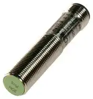
PRCM12-2DN
INDUCTIVE PROXIMITY SENSOR
⚠️ Reference pricing provided. In case of supply shortages, we will connect you with our trusted procurement partners to ensure your project's continuity.
- Manufacturer: AUTONICS
- Product type: Inductive Proximity Sensors
- Sensor Type:Inductive Proximity Sensor; Operating Temperature Max:70°C; Supply Voltage Min:12VDC; Supply Voltage Max:24VDC; Sensor Output Type:3-Wire, NPN, NO; Sensor Case 10R6710
- Sensor Type: Inductive Proximity Sensor
- Product Range: -
- Sensing Distance Nom: 2mm
- Sensor Case / Package: Cylindrical M12 Thread
| Delivery and price | |
|---|---|
| Units per pack | 1 |
| Price | 45.78 € |
| Current stock | 10+ |
| Lead time | 30 days |
Datasheet

Cylindrical Connector Type ~~ee~~

**==> picture [487 x 569] intentionally omitted <==**

**----- Start of picture text -----**<br>
Cylindrical connector type proximity sensor<br>(=|Features<br>@Shorten the time of maintenance entropy fp Few<br>@Improved the noise resistance with dedicated IC Lo hy { \ os<br>(DC 3-wire) y a<br>@Reverse powerovercurrent protection(DC) polarity (DC 3-wire), surge(AC/DC), Sepy \4<br>@Red eye ge a eS a ats<br>@IP67LEDratedstatuswaterproofindicationstructure (IEC standard) SO— eae.<br>@Replacer for micro switches and limit switches SG fs a a SY ‘<br>before using.<br>manual c E<br>™|Specifications<br>eDC 2-wire type<br>Model PRCMT12-2DO |PRCMT12-4DO |PRCMT18-5DO |PRCMT18-8DO |PRCMT30-10DO | [PRCMT30-15DO]<br>PRCMT12-2DC |PRCMT12-4DC |PRCMT18-5DC |PRCMT18-8DC |PRCMT30-10DC | [PRCMT30-15DC]<br>2mm +10% 4mm +10% 5mm +10% 8mm +10% | 10mm +10% | 15mm +10%<br>Max. 10% of sensing distance<br>Standard sensing 18x18 1mm 2525 x 1mm 30 301mm 4545 1mm<br>target 1212 1mm (Iron) (Iron) (Iron) (Iron) (Iron)<br>(Operation voltage) (10-30VDC)<br>Response 1.5kHz 500Hz 350Hz 400Hz 200Hz<br>frequency(*1)<br>Affection by Temp. +10% Max. for sensing distance at +20° within temperature range of —25 ~ +70C<br>Min. 50M (at 500VDC mega)<br>1500VAC 50/60Hz for 1 minute<br>1mm amplitude at frequency of 10 ~ 55Hz in each of X, Y, Z directions for 2 hours<br>500m/s? (50G) in X, Y, Z directions for 3 times<br>Operation indicator (Red LED)<br>—25 ~ +70 (at non-freezing status)<br>—30 ~ +80 (at non-freezing status)<br>Ambient humidity 35 ~ 95%RH<br>Surge protection circuit, Overload & Short circuit protection<br>IPG7CEC standard)<br>**----- End of picture text -----**<br>


**==> picture [28 x 13] intentionally omitted <==**

**----- Start of picture text -----**<br>
Proximity<br>**----- End of picture text -----**<br>


* (*1) The response frequency is the average value. The standard sensing target is used and the width is set as 2 times of the standard sensing target, 1/2 of the sensing distance for the distance. IEC standard item is available and add "—I" to the end of model. Ex) PRCM12—4DO-I % See J-—51 for IEC standard connector cables and specifications.

~~eee~~ Autonics J-24

PRCM Seriesa

## ~~ee~~

™|Specifications eDC 3-wire type

|eDC 3-wire|type||||||
|---|---|---|---|---|---|---|
|Model|**PRCM12-2D**N<br>P<br>PRCM12-2DN2 |<br>PRCM12-2DP2 ||**PRCM12-4D**N<br>P<br>| PRCM12-4DN2<br>| PRCM12-4DP2|PRCM18-5DP<br>**PRCM18-5D**N**2**<br>P<br>PRCML18-5DN<br>PRCML18-5DP<br>PRCML18-5DN2|<br>PRCML18-5DP2 ||PRCM18-8DP<br>**|PRCM18-8D**N**2**<br>P<br>|PRCML18-8DN<br>|PRCML18-8DP<br>|PRCML18-8DN2 <br>|PRCML18-8DP2|PRCM30-10DP<br>**|PRCM30-10D**N**2** **|**<br>P<br>|PRCML30-10DN |<br>|PRCML30-10DP<br> |PRCML30-10DN2|<br>|PRCML30-10DP2 ||PRCM30-15DP<br>**|PRCM30-15D**N**2**<br>P<br>|PRCML30-15DN<br>|PRCML30-15DP<br>|PRCML30-15DN2<br>|PRCML30-15DP2|
||||||||
||||||||
||||||||
||||||||
|(Operation voltage)|(10-30VDC)||||||
||||||||
||||||||
||||||||
||||||||
||||||||
||||||||
||||||||
||||||||
||||||||
||||||||
||||||||
||||||||
||||||||
||||||||
||||||||
||||||||
||||||||
|% (*1) The response frequency is the average value. The standard sensing target is used and the width is set as 2 times of the standard<br>sensing target, 1/2 of the sensing distance for the distance.<br>@AC 2-wire type|||||||
|Model|PRCM12-2A0<br>PRCM12-2AC|PRCM12-4A0<br>PRCM12-4AC|PRCM18-5AC<br>PRCML18-5AO |<br>PRCML18-5AC ||PRCM18-8AC<br>|PRCML18-8AO |<br>|PRCML18-8AC ||PRCM30-10AC<br>|PRCML30-10AO<br>|PRCML30-10AC||PRCM30-15AC<br>|PRCML30-15A0<br>|PRCML30-15AC|
||||||||
||||||||
||||||||
||||||||
|(Operation voltage)|(85-264VAC)||||||
||||||||
||||||||
||||||||
||||||||
||||||||
||||||||
||||||||
||||||||
||||||||
||||||||
||||||||
||||||||
||||||||
||||||||
||||||||
||||||||
||||||||


Cylindricala a Connector Type

~~OO————————————————————————————————————————————eeeeeeeeee—C—“‘“E~~

=|Dimensions

**==> picture [510 x 718] intentionally omitted <==**

**----- Start of picture text -----**<br>
Unit:mm<br>@PRCM(T)12-—2DT0) @PRCM(T)12—4D0<br>g21<br>7<br>indicator ely indicator<br>| in — | Operation g21 in|—_ Operation<br>; M12x1 \ Myo .c4 4 MI251 \ Miaxd<br>@PRCM(T)18—-5DL) PRCM(T)18—-8DL]<br>929 53.8 OperationOpe ° _ a8 Oo i<br>Il fi aC indicator ol | 1933.5 indicatorperation<br>HEI | ap LA<br>UID mtaie<br>\mtext \ waioscy UD AMIN og<br>@PRCM(T)30-10DL) @PRCM(T)30—-15DL)<br>83.8<br>42 63.8 $42<br>(F-\\ CAR (ES CIA<br>2 Hpdedit Ih io<br>SS HEAR | er) AE \ a<br>Z UL \ wg0% 1.5 M121 SE US on Mi2x4<br>@PRCM12-2AT | @PRCM12-4AL]<br>gai De Operation 921 oS nication<br>17 | 18.5 indicator 17 . 5<br>© HeesaD © Hiresip<br>L 4\mi2x1 M12x1 iW 4 \M12%4 M12x1<br>PRCM18-5AL] e@PRCM18-8AL]<br>24 35.3 indicator 24 10 35 3 indicator<br>| 929 39.5 Operation 929 39.5 Operation<br>| Ha<br>© —ipsa 1p 1 © Heaij |<br>wee \M12%1 UID \miext \ M121<br>@PRCM30-10AL] @PRCM30-—15AL]<br>42 63.8 42 63.8<br>a | indicator 7<br>G\\ ClAM (7-\\ HAG<br>A a co) CUE<br>SSE Ut \ M12x1 SE”Z LuiUi M12x1<br>5 M30X 1.5 pl 12 \ws0x1s<br>@PRCML18—5DL] / PRCML18-—5AL) e@PRCML18-—8DL() / PRCML18—-8AC]<br>l t<br>al 62 ro 10 52<br>He IG hit TAG<br>nee M18x1 M12x1 “elle? \wisx1 — \iext<br>@PRCML30—10DL] / PRCML30-10AL] e@PRCML30-—15DL] / PRCML30-15AC]<br>042 85.8 Operation 042 85.8 oneran<br>= indicator ro >peration<br>CFEN iy (EX Tan —H—<br>NZ, LHHH M121 wy)SSA HH M12*14<br>5 \M30x1.5 5 M30x 1.5<br>reer errr  rene e ner eee<br>Autonics J-26<br>**----- End of picture text -----**<br>


**==> picture [46 x 36] intentionally omitted <==**

**----- Start of picture text -----**<br>
W)<br>ee<br>**----- End of picture text -----**<br>


**==> picture [508 x 694] intentionally omitted <==**

**----- Start of picture text -----**<br>
PRCM Series<br>IE<br>™)Control output diagram<br>ODC 2-wire type ODC 3-wire type<br>NPN output type<br>Cy Brown O +V sone! > NO NC ) Brown 5 AV ; NO NC<br>= target L None target Lone 2 a =e<br>3 s 10kQ Load Operation<br>} ensing resence i a Ss resence<br>8 Load [ operation 1 aa g : Black (Brown—Black) L Return a nS<br>oO Cc<br>il BI Indicator frON 3 Cok gy Ly<br>3 O0V (LED) LOFF<br>OAC 2-wire type<br>PNP output type<br>(oo Toad] sensingeensing fr PresencePrese| Ne NC y Brown O+ : NO NC<br>AC . = Load Operation<br>3 target [None a5 2a i t Sensin cacserce_ ae<br>8 > Power ©) Load [ Overation is a g 4 Black (Brown—Black) L Return in nS<br>= o 10kQ Output voltage H<br>; Blue Indicator ON a ia = oa (Black—Blue) Lh EL na<br>(LED) TCOFF ; Blue 0 ov Indicatorcoy LorefON «= a<br>%* The number in a circle is pin no. of connector.<br>=|Wiring diagram<br>ODC 2-wire type(Standard type) ODC 2-wire type(IEC standard type)<br>Normal Open (NO) / Normal Close (NC) Normal Open (NO) Normal Close (NC)<br>B co B ron<br>(2) 4) ()) O 24VDC O 24VDC<br>@) @ Brown o 24voc] \@) @ Brown o2avoc] | SG OW<br>@ ® Blue O ov @®<br>Blue Blue Blue<br>O0V O OV O0V<br>* Pin M, @ are N.C (Not Connected) terminals. %* The pin arrangement of connector applying IEC standard is<br>* For DC 3-wire type connector cable, it is available to use being developed.<br>with black wire(24VDC) and blue wire (OV). Please attach "I" at the end of the name of standard type for<br>purchasing the IEC standard product. Ex) PRCMT12-—4DO-I<br>% The connector cable for IEC standard is being developed.<br>Please attach "I' at the end of the name of standard type.<br>Ex) CID2-—2-I, CLD2-5-I<br>ODC 3-wire OAC 2-wire<br>NPN output type PNP output type Normal Open(NO) / Normal Close(NC)<br>Brown Brown<br>OFS)@ O 24VDC @® @ ®) Black © 24VDC @  sO)® Brown @ ® ® © Brown<br>ue OV O OV u e ToaLoad<br>Bl | L m oy<br>%* Please fasten the cleat of connector not to shown the thread. >In AC inductive type, @ and @), @ and @ are connected<br>(0.39~0.49N ° m) inside of the connector cable.<br>**----- End of picture text -----**<br>


- Please fasten the vibration part with Teflon tape.

- See J—51 about IEC standard connector wires and specifications.

J-27

Autonics

Cylindricala a Connector Type ~~eee~~

**==> picture [539 x 730] intentionally omitted <==**

**----- Start of picture text -----**<br>
(=|Proper usage<br>OLoad connections<br>Brown Brown Brown<br>oei _ + {th — + cinrit = 100-<br>Lil |i i 2 [ha 24VDC (leo © s40vac<br>Te Mt | D | dre Bina " J UD Blue ,......, | 540/60Hz<br>Blue Blue ‘Coad! i Load:<br>< DC 2-wire type & AC 2—-wire type > < DC 2-wire type > < AC 2-wire type ><br>When using DC or AC 2-wire type proximity sensor, the load must be connected otherwise internal<br>components may be damaged. And the load can be connected to either wire.<br>Oln case of the load current is small<br>@AC 2-wire type<br>Brown It may cause return failure of load by residual voltage. If the load<br>Ain _ vn current is under 5mA, please make sure the residual voltage is<br>{f= lemn= Bleeder resistor(R) Osdwer less than the return voltage of the load by connecting a bleeder<br>Blue resistor in parallel with the load as shown in the diagram.<br>Vs ve<br>110VAC : 20kQ min. 3W R= > (Q) P= a (Ww)<br>220VAC + 39k min. TOW [ I:Action current of load, R:Bleeder resistance, P:Permissible power]<br>@DC 2-wire type Lo.<br>Please make the current on proximity sensor smaller than the<br>Brown return current of load by connecting a bleeder resistor in parallel.<br>{f= Bleeder' resistor(R): Vs %* Wdissipation.value of Bleed er resisVs tor should be  biggve ercw) for proper heat<br>Blue R= Torjorr (2? P eg Ww<br>[vs : Power supply, Io : Min. action current of proximity sensor |<br>Ioff : Return current of load, P : Number of Bleeder resistance watt<br>. . ())<br>OMutual—interference & Influence by surrounding metals Proximity<br>When several proximity sensors are mounted closely, malfunction of sensor may be caused due to mutual sensor<br>interference. Therefore, be sure to provide a minimum distance between the two sensors, as below charts.<br>A nin Im<br>Face [to] [Face] Sligea(HLS<br>When sensors are mounted on metallic panel, you must prevent the sensors from being affected by any<br>metallic object except target. Therefore, be sure to provide a minimum distance as below chart.<br>—t m<br>aT<br>CAE ad ?<br>Q<br>. Z | Lahp<br>(Unit:mm)<br>PRCMT12—2DL]| PRCMT12—4DL)} PRCMT18-—5D_ + |JPRCMT18—8DL] |PRCMT30-10DL] |PRCMT30-—15D<br>PRCM12-2DL] |PRCM12-—4DL] | PRCM(L)18—5D |PRCM(L)18—8DL]|PRCM(L)30—10DLJ]PRCM(L)30—15D<br>PRCM12-2AL] |PRCM12-—4AL] | PRCM(L)18—5A |PRCM(L)18—8AL] |PRCM(L)30—10AL] |PRCM(L)30—-15A<br>Pp A Tt lc<br>PB LT eT TT<br>|eGod || OOlt |CS<br>pomA TtYGts 8<br>rereeee eee reneerenee ener<br>Autonics J-28<br>**----- End of picture text -----**<br>
Updated at April 29, 2026
About Novapart
Novapart is a B2B electronic component broker specialising in stock shortages and cost reduction. We source hard-to-find parts and identify compliant alternatives across a catalogue of 410,000+ components from 500+ manufacturers.
Learn more →Stock Shortage Specialist
When a component is unavailable, discontinued or has an unacceptable lead time, we tap into our network of vetted European and Asian distributors to source what you need — without compromising on quality or traceability.
Request a quote →Compliant Alternatives
We identify pin-to-pin, electrically equivalent substitutes that meet the same certifications (RoHS, AEC-Q100, REACH) as your original specification — validated against datasheets, not just part numbers. Often at a lower cost.
BOM Analysis service →