
Image not available
Illustrative purposes only

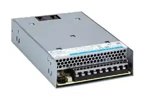
PMR-24V600W1BT
AC/DC Enclosed Power Supply (PSU), Terminal Block Conn, ITE & Household, 1 Outputs, 600 W, 24 V
⚠️ Reference pricing provided. In case of supply shortages, we will connect you with our trusted procurement partners to ensure your project's continuity.
- Manufacturer: DELTA ELECTRONICS
- Product type: AC / DC Enclosed Power Supplies
- SVHC: No SVHC (25-Jun-2025)
- Product Range: PMR-600W Series
- No. of Outputs: 1Outputs
- Output Power Max: 600W
- Input Voltage VAC: 90V AC to 264V AC
- Power Supply Output Type: Fixed
- Output Current - Output 1: 25A
- Output Current - Output 2: -
- Output Current - Output 3: -
- Output Current - Output 4: -
- Output Voltage - Output 1: 24V
- Output Voltage - Output 2: -
- Output Voltage - Output 3: -
- Output Voltage - Output 4: -
- Power Supply Applications: ITE & Household
| Delivery and price | |
|---|---|
| Units per pack | 50 |
| Price | 81.1 € |
| Current stock | 10+ |
| Lead time | 30 days |
Datasheet

**TECHNICAL DATASHEET**

**PMR Panel Mount Power Supply** PMR 600 W series / PMR- `□` V600W1BT

## **PMR**

## **Highlights & Features**

- Universal AC input voltage

- Built-in active PFC and conforms to harmonic current IEC/EN 61000-3-2, Class A and Class D

- Built-in Remote ON/OFF and Remote Sense

- Compact 1U low-profile design

- Add terminal block connector cover and conformal coating

- • Certified for household use (IEC/EN 60335-1, 61558-1, 61558-2-16)

- Compliant with IEC 61000-4-6 20V/m & semiconductor requirements.

- Wide operating temp -40°C ~70°C

## **Safety Standards**

CB Certified for worldwide use

**Model Number:** PMR- `☐` V600W1BT **Unit Weight:** 1.2 kg (2.65 lb) **Dimensions (L x W x H):** 225 x 124 x 41 mm (8.86 x 4.88 x 1.61 inch)

## **General Description**

PMR Series 600 W power supply offers the nominal output voltage of 12 V / 24 V / 36 V / 48 V across a wide operating temperature range from -40°C to +70°C and obtains shock and vibration certification IEC 60068-2. The product is designed with 1U low profile and comes with a universal AC input voltage ranging from 90 Vac to 264 Vac. The PMR series is made for installation in limited spaces. Its built-in active PFC circuit provides high power factor values and conforms to harmonic current emission standards IEC/EN 61000-3-2, Class A and Class D.

## **Model Information**

PMR Panel Mount Power Supply

|**ModelNumber**|**Input Voltage Range**|**Rated OutputVoltage**|**Rated Output Current**|
|---|---|---|---|
|PMR-12V600W1BT|90-264 Vac<br>(127-375 Vdc)|12 Vdc|50.0 A|
|PMR-24V600W1BT||24 Vdc|25.0 A|
|PMR-36V600W1BT||36 Vdc|16.6 A|
|PMR-48V600W1BT||48 Vdc|12.5 A|


## **Model Numbering**

|**PM**|**R –**|□**V**|**600W**|**1**|**B**|**T**|
|---|---|---|---|---|---|---|
|Panel<br>Mount|Product Type<br>R – Standard Rack Type<br>Series (1U)|Output Voltage<br>12 – 12 V<br>24 – 24 V<br>36 – 36 V<br>48 – 48 V|Output Power|Single Phase|Family Code<br>B – With Remote<br>Function|Connector Type<br>T – Terminal Block|


All parameters are specified at 25°C ambient and nominal AC input unless otherwise indicated. **www.DeltaPSU.com (Nov 2025, Rev. 04)**

1

**TECHNICAL DATASHEET**

**PMR Panel Mount Power Supply** PMR 600 W series / PMR- `□` V600W1BT

## **Specifications**

|Input Ratings / Characteristics|||||
|---|---|---|---|---|
|Nominal Input Voltage|100-240 Vac||||
|Input Voltage Range|90-264 Vac||||
|Nominal Input Frequency|50-60 Hz||||
|Input FrequencyRange|47-63 Hz||||
|DC Input Voltage Range*1|127-375 Vdc||||
|Input Current|6.0 A typ. @ 115 Vac, 3.0 A typ. @ 230 Vac||||
|Efficiencyat 100% Load@230 Vac|90.0% typ.|91.0% typ.|92.0% typ.|93.0% typ.|
|No Load Power Consumption|1.5 W typ. @ 230 Vac||||
|Max Inrush Current(Cold Start)|45 A typ.@230 Vac||||
|Power Factor at 100% Load|> 0.96@115 Vac & 230 Vac||||
|Leakage Current|< 0.8 mA @ 240 Vac||||


Input Ratings / Characteristics

*1 Power Supply can operate at DC Input voltage, please connect +pole to L, -pole to N and PE terminal to an earth wire or to the machine ground.

## Output Ratings / Characteristics*[2]

|Output Ratings / Characteristics*[2]|||||
|---|---|---|---|---|
|Nominal Output Voltage|12 Vdc|24 Vdc|36 Vdc|48 Vdc|
|Factory Set Point Tolerance|12 Vdc ± 1%|24 Vdc ± 1%|36 Vdc ± 1%|48 Vdc ± 1%|
|Output Voltage Adjustment Range|10.8-13.2 Vdc|21.6-26.4 Vdc|32.4-39.6 Vdc|43.2-52.8 Vdc|
|Output Current|0-50.0 A|0-25.0 A|0-16.6 A|0-12.5 A|
|Output Power|600.0 W Max.|600.0 W Max.|597.6 W Max.|600.0 W Max.|
|Line Regulation|± 0.5% typ. @ 115 Vac & 230 Vac||||
|Load Regulation|± 0.5% typ.||||
|PARD*3(20 MHz)|< 150 mVpp @ 0°C to 70°C<br>450 mVpptyp.@-30°C to 0°C||||
|Rise Time|30 ms typ. @ 115 Vac & 230 Vac||||
|Start-upTime|500 ms typ.@115 Vac & 230 Vac||||
|Hold-upTime|18 ms typ. @ 115 Vac & 230 Vac||||
|Dynamic Response<br>(Overshoot & Undershoot O/P Voltage)|± 10% @ 115 & 230 Vac input, 10-100% load<br>(Slew Rate: 2.5A/μS, 50% duty cycle @ 5Hz&10KHz)||||
|Start-upwith Capacitive Loads|8,000µF Max|8,000µF Max|6,000µF Max|5,000µF Max|


*2 For power de-rating from > 50°C to 70°C, see power de-rating on page 3.

*3 PARD is measured with an AC coupling mode, and in parallel to end terminal with 0.1µF ceramic capacitor & 47µF electrolytic capacitor. PSU need to burn in > 5 minutes when AMB ≤ 0°C

All parameters are specified at 25°C ambient and nominal AC input unless otherwise indicated. **www.DeltaPSU.com (Nov 2025, Rev. 04)**

2

**TECHNICAL DATASHEET PMR Panel Mount Power Supply** PMR 600 W series / PMR- `□` V600W1BT

## Mechanical

|Mechanical|Mechanical||
|---|---|---|
|Case Chassis||SGCC|
|Case Cover||SGCC|
|Dimensions (L x W x H)||225 x 124 x 41 mm(8.86 x 4.88 x 1.61 inch)|
|Unit Weight||1.2 kg (2.65 lb)|
|Indicator||Green LED(DC OK)|
|CoolingSystem||Force Cooling|
|Terminal|Input & Output|M3.5 x 9 Pins(Rated 300 V / 20 A)|
||CN100|Signal Connector: CVILUX CP3504P1H00-NH<br>Mating connector: CVILUX CP3504S0010 or equivalent|
|Wire||AWG 14-10<br>Current rating can refer to page 6 “Wire AWG Table”|


## Environment

|Environment||||
|---|---|---|---|
|Surrounding Air<br>Temperature|Operating||-40°C to +70°C|
||Storage||-40°C to +85°C|
|Power De-rating|||> 50°C de-rate power by 2% / °C<br>< 100Vac de-rate power by 1% / V<br>(90% load @ 90 Vac)|
|OperatingHumidity|||20 to 90%(Non-Condensing)|
|OperatingAltitude|||0 to 5,000 Meters(0 to 16,400 ft)|
|Shock Test|Non-Operating IEC 60068-2-27, Half Sine Wave: 50 G for duration of 11 ms; 3 times||Non-Operating IEC 60068-2-27, Half Sine Wave: 50 G for duration of 11 ms; 3 timesper direction|
|Vibration|Operating||IEC 60068-2-6, Sine Wave: 10 Hz to 500 Hz @ 2G ; 10 min per cycle, 60 min for each axis<br>(X,Y,Z)|
|Over Voltage Category|||II(Compliance to EN 62477-1 OVC III with 2000 meters altitude)|
|Pollution Degree|||3|
|Acoustic Noise*4||10% load,25°C|40 dB|
|||80% load,25°C|50 dB|


*4 Acoustic Noise test set up according to ISO-7779

All parameters are specified at 25°C ambient and nominal AC input unless otherwise indicated. **www.DeltaPSU.com (Nov 2025, Rev. 04)**

3

**TECHNICAL DATASHEET PMR Panel Mount Power Supply** PMR 600 W series / PMR- `□` V600W1BT

## Protections

|Protections|||||
|---|---|---|---|---|
|Overvoltage|13.2 V - 16.8 V<br>SELV Output,<br>Latch Mode|26.4 V - 33.6 V<br>SELV Output,<br>Latch Mode|39.6 V - 48.6 V<br>SELV Output,<br>Latch Mode|52.8 V - 64.8 V<br>SELV Output,<br>Latch Mode|
|Overload / Overcurrent|105 - 150% of rated load current, Auto-recovery<br>Continuous current limit Mode*5(Vo > 80%)||||
|Over Temperature|Auto-recovery||||
|Short Circuit|Hiccup Mode, Non-Latching<br>(Auto-Recoverywhen the fault is removed)||||
|Internal Fuse at L pin|T10 A / 250 V||||
|Protection Against Shock|Class I with PE*6connection||||


*5 Constant current limit protection for inductive and capacitive load applications

*6 PE: Protection Earth

## Reliability Data

|MTBF|> 700,000 hrs as per Telcordia SR-332|
|---|---|
||(I/P: 230 Vac, O/P: 100% Load, Ta: 25°C)|
|Expected Cap Life Time|10 years (230 Vac, 50% load @ 40°C)|


## Safety Standards / Directives

|SafetyEntryLow Voltage|SafetyEntryLow Voltage|SELV|
|---|---|---|
|Electrical Safety|TUV Bauart<br>UL/cUL<br>CB scheme<br>EAC<br>BSMI<br>CCC<br>BIS|EN 62368-1, EN 60335-1<br>UL 62368-1, and CAN/CSA C22.2 No. 62368-1<br>IEC 62368-1, IEC 60335-1, IEC/EN 61558-1/-2-16<br>TP TC 004/2011<br>CNS 15598-1<br>GB4943.1-2022<br>IS 13252(Part 1)|
|CE||In conformance with EMC Directive 2014/30/EU and Low Voltage Directive 2014/35/EU|
|UKCA||In conformance with Electromagnetic Compatibility Regulations 2016 and Electrical<br>Equipment (Safety) Regulations 2016|
|Galvanic Isolation|Input to Output|4.0 KVac|
||Input to Ground|2.0 KVac|
||Output to Ground|1.25 KVac|


All parameters are specified at 25°C ambient and nominal AC input unless otherwise indicated. **www.DeltaPSU.com (Nov 2025, Rev. 04)**

4

**TECHNICAL DATASHEET PMR Panel Mount Power Supply** PMR 600 W series / PMR- `□` V600W1BT

## EMC[*7]

|EMC[*7]||||
|---|---|---|---|
|Emissions<br>(CE & RE)|CISPR 32, EN/BS EN 55032, KS C 9832, AS/NZS CISPR32 & Compliance to FCC Title 47,<br>EN/BS EN 55014-1 , EN/BS 61000-6-3 , EN/BS EN 61000-6-4 : Class B|||
|Immunity|EN/BS EN 55035, KS C 9835, & Compliance to EN/ BS EN 55014-2 , EN/BS EN 61000-6-<br>1 , EN/BS EN 61000-6-2|||
|Electrostatic<br>Discharge<br>IEC 61000-4-2|Level 4 Criteria A1)<br>Air Discharge: 15 kV<br>Contact Discharge: 8 kV|||
|Radiated Field<br>IEC 61000-4-3|Level 3 Criteria A1)<br>80 MHz – 1 GHz, 10 V/M, 80% Modulation (1 kHz)<br>1.4 GHz – 6 GHz,3 V/M,80% Modulation(1 kHz)|||
|Electrical Fast<br>Transient / Burst<br>IEC 61000-4-4|Level 3 Criteria A1)<br>2 kV|||
|Surge<br>IEC 61000-4-5|Level 4 Criteria A1)<br>Common Mode4): 4 kV<br>Differential Mode5): 2 kV|||
|Conducted<br>IEC 61000-4-6|Level 3 Criteria A1)<br>150 kHz-80 MHz,20 Vrms|||
|Power Frequency<br>Magnetic Fields<br>IEC 61000-4-8|Level 4 Criteria A1)<br>30 A/Meter|||
|Voltage Dips and<br>Interruptions<br>IEC 61000-4-11|0% residual; 1 cycle, Criteria B2)<br>40% residual; 10 cycle, Criteria C3)<br>70% residual;25 cycle,Criteria C3)|||
|Harmonic Current<br>Emission|IEC/EN/BS EN 61000-3-2, Class A & Class D|||
|Voltage Fluctuation<br>and Flicker|IEC/EN/BS EN 61000-3-3|||
|Voltage Sag Immunity<br>SEMI F47 – 0706|80% of 200 Vac<br>70% of 200 Vac<br>50% of 200 Vac|160 Vac, 1000 ms<br>140 Vac, 500 ms<br>100 Vac,200 ms|Criteria A1)<br>Criteria A1)<br>Criteria A1)|


- 1) Criteria A: Normal performance within the specification limits

- 2) Criteria B: Output out of regulation, or shuts down during test. Automatically restored to normal operation after test.

- 3) Criteria C: Output out of regulation, shuts down during test (Need to recycle AC power cord to normal operation after test)

- 4) Asymmetrical: Common mode (Line to earth)

- 5) Symmetrical: Differential mode (Line to line)

- *7 Power supply is considered a component in the end-user's system. Please contact our local sales to get more information about the power supply EMC test setup.

All parameters are specified at 25°C ambient and nominal AC input unless otherwise indicated. **www.DeltaPSU.com (Nov 2025, Rev. 04)**

5

**TECHNICAL DATASHEET**

## **PMR Panel Mount Power Supply** PMR 600 W series / PMR- `□` V600W1BT

## **Block Diagram**

**==> picture [514 x 276] intentionally omitted <==**

**----- Start of picture text -----**<br>
Fan Control<br>Transformer &<br>Power Stage<br>L PFC Converter —> Vo+<br>& Inrush current  DC/DC Output Rectifier<br>AC Input EMI Filter limit Converter Filter DC Output<br>& Filter<br>N Vo-<br>| Rs+<br>Remote Sense Circuit<br>Rs-<br>Photo Coupler &<br>Feedback Control<br>Over Temperature  PWM Control  (CV & CC)<br>Protection<br>Photo Coupler &<br>Over Voltage<br>Protection<br>Photo Coupler & Rc+<br>—————|<br>Remote Control<br>Circuit<br>————————_______9<br>Rc-<br>**----- End of picture text -----**<br>


## **Device Descriptions**

- 1) Input & Output terminal block connector 2) DC voltage adjustment potentiometer

- 3) DC OK control LED (Green)

- 4) Remote ON/OFF and Remote Sense connector

All parameters are specified at 25°C ambient and nominal AC input unless otherwise indicated. **www.DeltaPSU.com (Nov 2025, Rev. 04)**

6

**TECHNICAL DATASHEET**

## **PMR Panel Mount Power Supply** PMR 600 W series / PMR- `□` V600W1BT

## **Dimensions**

**L x W x H:** 225 x 124 x 41 mm (8.86 x 4.88 x 1.61 inch)

**==> picture [161 x 70] intentionally omitted <==**

**----- Start of picture text -----**<br>
ITEM PART NAME<br>1 COVER<br>2 CHASSIS<br>3 INPUT / OUTPUT CONNECTOR<br>4 FAN<br>5 OUTPUT VOLTAGE ADJUST<br>6 OUTPUT CONNECTOR(CVILUX CP3504P1H00-NH)<br>7 LED<br>**----- End of picture text -----**<br>


**Note: Built-in cooling fan. Must prevent dust suction into power supply, or use natural convection power supply if any concerns.**

## **Wire AWG Table**

|**Wire AWG Table**|**Wire AWG Table**|**Wire AWG Table**|**Wire AWG Table**|
|---|---|---|---|
|**Current rating for PVC Wire AWG**||||
|6 AWG|52.5 A|20 AWG|6.5 A|
|8 AWG|37.5 A|22 AWG|5.0 A|
|10 AWG|29.0 A|24 AWG|3.5 A|
|12 AWG|22.5 A|26 AWG|2.5 A|
|14 AWG|16.5 A|28 AWG|2.0 A|
|16 AWG|12.0 A|30 AWG|1.5 A|
|18 AWG|9.0 A|||


All parameters are specified at 25°C ambient and nominal AC input unless otherwise indicated. **www.DeltaPSU.com (Nov 2025, Rev. 04)**

7

**TECHNICAL DATASHEET**

## **PMR Panel Mount Power Supply** PMR 600 W series / PMR- `□` V600W1BT

## **Engineering Data**

Output Load De-rating VS Surrounding Air Temperature

**==> picture [318 x 192] intentionally omitted <==**

**----- Start of picture text -----**<br>
110<br>100<br>90<br>80<br>70<br>60<br>50<br>40<br>30<br>20<br>10<br>0<br>-40 -30 -20 -10 0 10 20 30 40 50 60 70<br>Surrounding Air Temperature ( [o] C)<br>Percentage of Max Load (%)<br>**----- End of picture text -----**<br>


## **Fig. 1 De-rating for Horizontal Mounting Orientation** > 50°C de-rate power by 2.0% / °C

## **Note**

1. Power supply components may degrade, or be damaged, when the power supply is continuously used outside the shaded region, refer to the graph shown in Fig. 1 & Fig. 2.

2. The power supply will have long rise time when the ambient temperature range is -30°C to -40°C.

3. If the output capacity is not reduced when the surrounding air temperature >50°C, the device will run into Over Temperature Protection. When activated, power supply will latch off, until the surrounding air temperature is lowered or the load is reduced as far as necessary to keep the device in working condition, and require removal/re-application of input AC voltage in order to restart.

4. In order for the device to function in the manner intended, it is also necessary to keep a safety distance as recommended in the safety instructions while the device is in operation.

5. Depending on the surrounding air temperature and output load delivered by the power supply, the device can be very hot!

Output Load De-rating VS Input Voltage

- No output power de-rating for the input voltage from 100 Vac to 264 Vac & 127 Vdc to 375 Vdc

**==> picture [111 x 9] intentionally omitted <==**

**----- Start of picture text -----**<br>
AC Input     DC Input<br>**----- End of picture text -----**<br>


## **Fig. 2 De-rating for AC Input Voltage**

< 100Vac de-rate power by 1% / V (90% load @ 90 Vac) No de-rate power for DC Input

All parameters are specified at 25°C ambient and nominal AC input unless otherwise indicated. **www.DeltaPSU.com (Nov 2025, Rev. 04)**

8

## **TECHNICAL DATASHEET PMR Panel Mount Power Supply** PMR 600 W series / PMR- `□` V600W1BT

## **Assembly & Installation**

- Ⓐ   Mounting: Fig. 3 shows the mounting hole locations for power supply assembly onto a metal mounting surface.

- Ⓑ   This surface belongs to customer’s end system or panel where the power supply is mounted.

- Ⓒ Connector

**==> picture [46 x 9] intentionally omitted <==**

**----- Start of picture text -----**<br>
Mounting<br>**----- End of picture text -----**<br>


- If the device has to be mounted in any other orientation, please leave a message via the Contact Us form.

- Use flexible cable (stranded or solid) of AWG No.14-10. User should calculate and select the suitable wire specification (type/quantity/diameter) according to actual output current. The torque at the Connector shall not exceed 12.4 Kgf.cm. (10.54 lbf.in). The insulation stripping length should not exceed 0.275” or 7 mm. (Refer to Fig. 3).

Installation of Mounting Accessories

**==> picture [128 x 9] intentionally omitted <==**

**----- Start of picture text -----**<br>
Fig. 3  Assembly Reference<br>**----- End of picture text -----**<br>


All parameters are specified at 25°C ambient and nominal AC input unless otherwise indicated. **www.DeltaPSU.com (Nov 2025, Rev. 04)**

9

**TECHNICAL DATASHEET**

**PMR Panel Mount Power Supply** PMR 600 W series / PMR- `□` V600W1BT

-

-

- Only use M4 screw ≤ 3 mm (0.20 inch) through the base mounting holes. This is to keep a safe distance between the screw and internal components.

Recommended mounting tightening torque: 4~5 Kgf.cm (3.47~4.33 lbf.in).

## **Fig. 4 Mounting Screw**

## Safety Instructions

- If user’s mounting orientation is not according to the recommended mounting orientations, please consult Delta for further information.

- To ensure sufficient convection cooling, always maintain a safety distance of ≥ 50 mm (1.97 inch) from all ventilated surfaces while the device is in operation.

- The device is not recommended to be placed on low thermal conductive surface. For example, plastics.

- The enclosure of the device can become very hot depending on the ambient temperature and load of the power supply. Do not touch the device while it is in operation or immediately after power is turned OFF. Risk of burning!

- Do not touch the terminals while power is being supplied. Risk of electric shock.

- Prevent any foreign metal, particles or conductors from entering the device through the openings during installation. It may cause: Electric shock; Safety Hazard; Fire; Product failure

- The power supply must be mounted by metal screws onto a grounded metal surface. It is highly recommended that the Earth terminal on the connector be connected to the grounded surface.

All parameters are specified at 25°C ambient and nominal AC input unless otherwise indicated. **www.DeltaPSU.com (Nov 2025, Rev. 04)**

10

**TECHNICAL DATASHEET**

## **PMR Panel Mount Power Supply** PMR 600 W series / PMR- `□` V600W1BT

## **Functional Manual**

## Remote ON/OFF Function

You can remotely control the power supply unit to turn ON/OFF by using an external DC source. Follow the DC power source voltage and current limiting defined in the table below.

**Voltage Between RC+ and RC- (V) Built-in Resistor Ri (ohm) Input Current (mA)** ~~S|ee~~ **Output ON Output OFF** ~~eee~~ 1000 0-0.5 5-12.5 20 Max

## **Notes**

1. Remote ON/OFF circuits are isolated from input, output and PE.

2. Please check if the polarity of the wire connector is the same as the external DC source. If not, the power would not turn on and the internal components may be damaged.

3. You do not need an external resistance RO for current limit while the output voltage of external DC source is within the range of 5-12.5 V. If the output voltage exceeds 12.5 V, please use the following equation for the value of current limit resistance RO.

𝑅𝑂 =[𝑉𝑐𝑐−(3.5 + 0.006𝑅] 0.006[𝑖][)]

## Remote Sensing Function

This function compensates voltage drop of wiring from output terminals to load terminals. Connect “RS+” of CN100 terminal to “V+” terminal of load and “RS-” of CN100 terminal to “V-” terminal of load with sensing wires. The total compensates voltage drop up to 0.5 V. * In case that output wiring is too long and wire AWG is too small, OVP may be triggered, please contact us for more details via the Contact Us form.

Sense lines should be twisted in pairs

All parameters are specified at 25°C ambient and nominal AC input unless otherwise indicated. **www.DeltaPSU.com (Nov 2025, Rev. 04)**

11

**TECHNICAL DATASHEET**

**PMR Panel Mount Power Supply** PMR 600 W series / PMR- `□` V600W1BT

## **Functions**

## Start-up Time

The time required for the output voltage to reach 90% of its final steady state set value, after the input voltage is applied.

## Rise Time

The time required for the output voltage to change from 10% to 90% of its final steady state set value.

## Hold-up Time

Time between the collapse of the AC input voltage, and the output falling to 95% of its steady state set value.

## ■ **Graph illustrating the Start-up Time, Rise Time, and Hold-up Time**

## Inrush Current

Inrush current is the peak, instantaneous, input current measured and, occurs when the input voltage is first applied. For AC input voltages, the maximum peak value of inrush current will occur during the first half cycle of the applied AC voltage. This peak value decreases exponentially during subsequent cycles of AC voltage.

## Dynamic Response

The power supply output voltage will remains within ± 10% of its steady state value, when subjected to a dynamic load from 10% to 100%.

All parameters are specified at 25°C ambient and nominal AC input unless otherwise indicated. **www.DeltaPSU.com (Nov 2025, Rev. 04)**

12

**TECHNICAL DATASHEET**

**PMR Panel Mount Power Supply** PMR 600 W series / PMR- `□` V600W1BT

## Overload & Overcurrent Protections (Continuous Current)

The power supply offers constant current limit protection for inductive and capacitive load applications when output current range is 105~150% of IO (Max load) and output voltage large than 80%. Upon such an occurrence, the VO (output voltage) will start to droop. Once the power supply has reached its maximum power limit, the protection will be activated; and, the power supply will operate in continuous current. The power supply will recover once the cause of OLP or OCP is removed, and IO (output current) is back within the specified range.

## Overvoltage Protection (Auto-Recovery)

The power supply’s overvoltage circuit will be activated when its internal feedback circuit fails. The output voltage shall not exceed its specifications defined on Page 4 under “Protections”.

## Over Temperature Protection (Auto-Recovery)

As described in load de-rating section, the power supply also has Over Temperature Protection (OTP). In the event of a higher operating temperature at 100% load, the power supply will run into OTP when the operating temperature is beyond what is recommended in the de-rating graph. When activated, the output voltage will go into bouncing mode until the temperature drops to its normal operating temperature as recommended in the de-rating graph.

## Short Circuit Protection (Auto-Recovery)

The power supply’s output OLP/OCP function also provides protection against short circuits. When a short circuit is applied, the output current will operate in “Hiccup mode”, as shown in the illustration in the OLP/OCP section on this page. The power supply will return to normal operation after the short circuit is removed.

## **Others**

## Attention

Delta provides all information in the datasheets on an “AS IS” basis and does not offer any kind of warranty through the information for using the product. In the event of any discrepancy between the information in the catalog and datasheets, the datasheets shall prevail (please refer to www.DeltaPSU.com for the latest datasheets information). Delta shall have no liability of indemnification for any claim or action arising from any error for the provided information in the datasheets. Customer shall take its responsibility for evaluation of using the product before placing an order with Delta.

Delta reserves the right to make changes to the information described in the datasheets without notice.

## **Manufacturer and Authorized Representatives Information**

## Manufacturer

Thailand Taiwan Delta Electronics (Thailand) PCL. Delta Electronics, Inc. 909 Pattana 1 Rd., Muang, Samutprakarn, 10280 Thailand 3 Tungyuan Road, Chungli Industrial Zone, Taoyuan County 32063, Taiwan

## Authorized Representatives

The Netherlands United Kingdom Delta Greentech (Netherlands) B.V. Delta Electronics Europe Limited Zandsteen 15, 2132 MZ Hoofddorp, The Netherlands 1 Redwood Court, Peel Park Campus, East Kilbride, Glasgow, G74 5PF, United Kingdom

All parameters are specified at 25°C ambient and nominal AC input unless otherwise indicated. 13 **www.DeltaPSU.com (Nov 2025, Rev. 04)**
Updated at June 5, 2026
About Novapart
Novapart is a B2B electronic component broker specialising in stock shortages and cost reduction. We source hard-to-find parts and identify compliant alternatives across a catalogue of 540,000+ components from 500+ manufacturers.
Learn more →Stock Shortage Specialist
When a component is unavailable, discontinued or has an unacceptable lead time, we tap into our network of vetted European and Asian distributors to source what you need — without compromising on quality or traceability.
Request a quote →Compliant Alternatives
We identify pin-to-pin, electrically equivalent substitutes that meet the same certifications (RoHS, AEC-Q100, REACH) as your original specification — validated against datasheets, not just part numbers. Often at a lower cost.
BOM Analysis service →