


PM4HA-H-AC240V
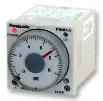
Analogue Timer, DIN48, PM4H-A, Multifunction, 16 Ranges, 1 s, 500 h, 2 Changeover Relays
- Manufacturer: PANASONIC
- Product type: Analogue Timers
- Time Max: 500h
- Time Min: 1s
- Timer Output: 2 Changeover Relays
- Product Range: PM4H-A
- Timer Functions: Multifunction
- Current Rating Nom: 5A
- Panel Cutout Width: 45mm
- Supply Voltage Max: 240VAC
- Panel Cutout Height: 45mm
- No. of Timing Ranges: 16Ranges
- Connection / Termination: Plug-In
| Delivery and price | |
|---|---|
| Units per pack | 20 |
| Price | 31.09 € |
| Current stock | 10+ |
| Lead time | 30 days |
**PM4H-A/S/M**

## **DIN48 SIZE MULTI-RANGE ANALOG TIMER**

## **PM4H-A PM4H-S - PM4H M**

**==> picture [15 x 10] intentionally omitted <==**

**----- Start of picture text -----**<br>
48<br>1.890<br>**----- End of picture text -----**<br>


**UL File No.: E122222 CSA File No.: LR39291**

## Al G

## **Features**

- **100-240V AC free-voltage input, 48-125V DC type available**

- **Short body — 62.5mm 2.461 inch (screw terminal type)**

- **Front panel of IP65 type is protected against water-splash and dust**

- **Built-in Screw terminals**

**==> picture [442 x 54] intentionally omitted <==**

**----- Start of picture text -----**<br>
48 62.52.461 Screw terminal type is used for easy wiring and reducing additional cost for<br>1.890 mm inch accessories.<br>•  0 setting instantaneous output operation<br>•  Multiple time ranges — 1 s to 500 h (Max.)<br>Screw<br>Pin type terminal type •  8 different operation modes: (PM4H-A)<br>&<br>**----- End of picture text -----**<br>


- **8 different operation modes: (PM4H-A) •  Compliant with UL/CSA, CE and LLOYD**

## **Product types**

|**Type**|**Operation mode**<br>~~CC~~|**Contact**<br>**arrangement**<br>~~CC~~|**Time range**<br>~~CC~~|**Protective**<br>**construction**<br>~~CCS~~|**Rated**<br>**operating voltage**<br>~~S~~|**Terminal type**<br>~~S~~|**Part number**|
|---|---|---|---|---|---|---|---|
|**PM4H-A**|8 operation modes<br>•Pulse ON-delay<br>•Pulse Flicker<br>•Pulse ON-flicker<br>•Differential ON/OFF-delay (1) (2)<br>•Signal OFF-delay<br>•Pulse One-shot<br>•Pulse One-cycle<br>~~CC~~|Relay<br>Timed-out<br>2 Form C<br>~~CC~~|16 selectable<br>ranges<br>1s to 500h<br>~~CC~~|IP65<br>~~CCS~~<br>~~es~~<br>~~a~~<br>~~e~~<br>~~ee~~|100 to 240V AC<br>~~S~~<br>~~es~~|11pins<br>~~S~~<br>~~es~~|PM4HA-H-AC240VW|
|||||||Screw terminal<br>~~es~~|PM4HA-H-AC240VSW|
||||||48 to 125V DC<br>~~a~~|11pins<br>~~a~~|PM4HA-H-DC125VW|
|||||||Screw terminal<br>~~a~~|PM4HA-H-DC125VSW|
||||||24V AC/DC<br>~~a~~<br>~~ee~~<br>~~ee~~|11pins<br>~~a~~<br>~~e~~|PM4HA-H-24VW|
|||||||Screw terminal<br>~~e~~<br>~~ee~~|PM4HA-H-24VSW<br>~~ee~~|
||||||12V DC<br>~~ee~~<br>~~ee~~|11pins<br>~~e~~<br>~~ee~~|PM4HA-H-DC12VW<br>~~ee~~|
|||||||Screw terminal<br>~~ee~~|PM4HA-H-DC12VSW<br>~~ee~~|
|||||IP50<br>~~ee~~<br>~~a~~<br>~~e~~<br>~~ee~~<br>~~e~~|100 to 240V AC<br>~~ee ~~<br>~~a~~|11pins<br> ~~ee~~<br>~~a~~|PM4HA-H-AC240V<br>~~ee~~|
|||||||Screw terminal<br>~~a~~|PM4HA-H-AC240VS|
||||||48 to 125V DC<br>~~a~~<br>~~ee~~<br>~~ee~~|11pins<br>~~a~~<br>~~e~~|PM4HA-H-DC125V|
|||||||Screw terminal<br>~~e~~<br>~~ee~~|PM4HA-H-DC125VS<br>~~ee~~|
||||||24V AC/DC<br>~~ee~~<br>~~ee~~|11pins<br>~~e~~<br>~~ee~~|PM4HA-H-24V<br>~~ee~~|
|||||||Screw terminal<br>~~ee~~|PM4HA-H-24VS<br>~~ee~~|
||||||12V DC<br>~~ee ~~<br>~~ee~~|11pins<br> ~~ee~~<br>~~e~~|PM4HA-H-DC12V<br>~~ee~~|
|||||||Screw terminal<br>~~e~~|PM4HA-H-DC12VS|
|**PM4H-S**|Power ON-delay|Relay<br>Timed-out<br>2 Form C||IP65<br>~~e~~<br>~~e~~<br>~~|OL~~<br>~~e~~<br>~~ee~~<br>~~|~~|100 to 240V AC<br>~~ee~~<br>~~ee~~<br>~~|~~|8pins<br>~~e~~<br>~~e~~|PM4HS-H-AC240VW|
|||||||Screw terminal<br>~~e~~<br>|PM4HS-H-AC240VSW|
||||||48 to 125V DC<br>~~ee~~<br>~~|OL~~|8pins<br>~~e~~<br>~~OL~~|PM4HS-H-DC125VW|
|||||||Screw terminal<br>~~OL~~|PM4HS-H-DC125VSW|
||||||24V AC/DC<br>~~|~~<br>~~ee~~|8pins<br><br>~~e~~|PM4HS-H-24VW|
|||||||Screw terminal<br>~~e~~|PM4HS-H-24VSW|
||||||12V DC<br>~~ee~~<br>~~ee~~<br>~~|~~|8pins<br>~~e~~<br>~~ee~~|PM4HS-H-DC12VW|
|||||||Screw terminal<br>~~ee~~<br>|PM4HS-H-DC12VSW|
|||||IP50<br>~~|i~~<br>~~P~~<br>~~ee~~<br>~~|OL~~|100 to 240V AC<br>~~|i~~|8pins<br>~~i~~|PM4HS-H-AC240V|
|||||||Screw terminal<br>~~i~~|PM4HS-H-AC240VS|
||||||48 to 125V DC<br>~~|~~<br>~~PCL~~<br>~~ee~~|8pins<br><br>~~CL~~|PM4HS-H-DC125V|
|||||||Screw terminal<br>~~CL~~<br>~~ee~~|PM4HS-H-DC125VS<br>~~ee~~|
||||||24V AC/DC<br>~~PCL~~<br>~~ee~~<br>~~|~~|8pins<br>~~CL~~<br>~~ee~~|PM4HS-H-24V<br>~~ee~~|
|||||||Screw terminal<br>~~ee~~<br>|PM4HS-H-24VS<br>~~ee~~|
||||||12V DC<br>~~ee ~~<br>~~|OL~~|8pins<br> ~~ee~~<br>~~OL~~|PM4HS-H-DC12V<br>~~ee~~|
|||||||Screw terminal<br>~~OL~~|PM4HS-H-DC12VS|
|**PM4H-M**|5 operation modes<br>(With instantaneous contact)<br>•Power ON-delay<br>•Power Flicker<br>•Power ON-flicker<br>•Power One-shot<br>•Power One-cycle|Relay<br>Timed-out<br>1 Form C<br>Instantaneous<br>1 Form C||IP65<br>~~|~~<br>~~a~~<br>~~ee~~<br>~~P~~<br>~~ee~~<br>~~ee~~|100 to 240V AC<br>~~|~~<br>~~a~~|8pins<br><br>~~a~~|PM4HM-H-AC240VW|
|||||||Screw terminal<br>~~a~~|PM4HM-H-AC240VSW|
||||||48 to 125V DC<br>~~a~~<br>~~ee~~|8pins<br>~~a~~<br>~~ee~~|PM4HM-H-DC125VW|
|||||||Screw terminal<br>~~ee~~|PM4HM-H-DC125VSW|
||||||24V AC/DC<br>~~PL~~|8pins<br>~~L~~|PM4HM-H-24VW|
|||||||Screw terminal<br>~~L~~|PM4HM-H-24VSW|
||||||12V DC<br>~~PL~~<br>~~ee~~<br>~~ee~~|8pins<br>~~L~~<br>~~ee~~|PM4HM-H-DC12VW|
|||||||Screw terminal<br>~~ee~~<br>~~ee~~|PM4HM-H-DC12VSW<br>~~ee~~|
|||||IP50<br>~~ee~~<br>~~P~~<br>~~ee~~<br>~~ee~~|100 to 240V AC<br>~~ee~~|8pins<br>~~ee~~|PM4HM-H-AC240V<br>~~ee~~|
|||||||Screw terminal<br>~~ee~~|PM4HM-H-AC240VS<br>~~ee~~|
||||||48 to 125V DC<br>~~ee ~~<br>~~PUL~~|8pins<br> ~~ee~~<br>~~UL~~|PM4HM-H-DC125V<br>~~ee~~|
|||||||Screw terminal<br>~~UL~~|PM4HM-H-DC125VS|
||||||24V AC/DC<br>~~PUL~~<br>~~ee~~<br>~~ee~~|8pins<br>~~UL~~<br>~~ee~~|PM4HM-H-24V|
|||||||Screw terminal<br>~~ee~~<br>~~ee~~|PM4HM-H-24VS<br>~~ee~~|
||||||12V DC<br>~~ee~~|8pins<br>~~ee~~|PM4HM-H-DC12V<br>~~ee~~|
|||||||Screw terminal<br>~~ee~~|PM4HM-H-DC12VS<br>~~ee~~|


If you use this timer under harsh environment, please order above sealed type (IP65 type). IP65 type — Protection dust and water jet splay on the front face. 09/2009

38

**PM4H-A/S/M**

## **Time range**

|Scale<br>Time unit|Scale<br>Time unit|sec|min|hrs|10h|
|---|---|---|---|---|---|
|1|Control<br>time range|0.1s to 1s|0.1 min to 1 min|0.1h to 1h|1.0h to 10h|
|5||0.5s to 5s|0.5 min to 5 min|0.5h to 5h|5h to 50h|
|10||1.0s to 10s|1.0 min to 10 min|1.0h to 10h|10h to 100h|
|50||5s to 50s|5 min to 50 min|5h to 50h|50h to 500h|


PM4H-A/PM4H-S/PM4H-M All types of PM4H timer have multi-time range.

16 time ranges are selectable. 1s to 500h (Max. range) is controlled.

Note: 0 setting is for instantaneous output operation.

## **Specifications**

|**Item**|**Type**|**Type**|**PM4H-A**|**PM4H-S**|**PM4H-M**|
|---|---|---|---|---|---|
|**Rating**|**Rated operating voltage**||100 to 240V AC,48 to 125V DC,12V DC,24V AC/DC|||
||**Rated frequency**||50/60Hz common(AC operatingtype)|||
||**Rated power consumption**||Approx. 10VA (100 to 240V AC)<br>Approx. 2.5VA (24V AC)<br>Approx. 1.5W(12V DC,24V DC,48 to 125V DC)|||
||**Rated control capacity**||5A 250V AC(resistive load)|||
||**Operating mode**||Pulse ON-delay<br>Pulse Flicker<br>Pulse ON-Flicker<br>Differential ON/OFF-delay (1) (2)<br>Signal OFF-delay<br>Pulse One-shot<br>Pulse One-cycle|Power ON-delay|Power ON-delay<br>Power Flicker<br>Power ON-flicker<br>Power One-shot<br>Power One-cycle<br>(with instantaneous contact)|
||**Time range**||1s to 500h(Max.)16 time ranges switchable|||
|**Time**<br>**accuracy**<br>**Note:1)**|**Operating time fluctuation**||�0.3%(power off time change at the range of 0.1s to 1h)|||
||**Setting error**||�5%(Full-scale value)|||
||**Voltage error**||�0.5%(at the operatingvoltage changes between 85 to 110%)|||
||**Temperature error**||�2%(at 20�C ambient temp. at the range of –10 to +50�C+14 to +122�F)|||
|**Contact**|**Contact arrangement**||Timed-out 2 Form C||Timed-out 1 Form C<br>Instantaneous 1 Form C|
||**Contact resistance(Initial value)**||Max. 100m� (at 1A 6V DC)|||
||**Contact material**||Silver alloy||Au flash on Silver alloy|
|**Life**|**Mechanical(contact)**||2�107|||
||**Electrical(contact)**||105 (at rated control capacity)|||
|**Electrical**<br>**function**|**Allowable operating voltage range**||85 to 110% of rated operatingvoltage(at 20�C coil temp.)|||
||**Insulation resistance (Initial value)**||Between live and dead metal parts<br>Between input and output<br>Between contacts of different poles<br>Between contacts of samepole<br>Min. 100M�<br>(At 500V DC)|||
||**Breakdown voltage (Initial value)**||2,000Vrms for 1 min Between live and dead metal parts<br>2,000Vrms for 1 min Between input and output<br>2,000Vrms for 1 min Between contacts of different poles<br>1,000Vrms for 1 min Between contacts of samepole|||
||**Min.power off time**||100ms|||
||**Max. temperature ris**|**e**|55�C131�F||65�C149�F|
|**Mechanical**<br>**function**|**Vibration resistance**|**Functional**|10 to 55Hz: 1 cycle/min double amplitude of 0.25mm(10min on 3 axes)|||
|||**Destructive**|10 to 55Hz: 1 cycle/min double amplitude of 0.375mm(1h on 3 axes)|||
||**Shock resistance**|**Functional**|Min. 98m/s2 (4 times on 3 axes)|||
|||**Destructive**|Min. 980m/s2 (5 times on 3 axes)|||
|**Operating**<br>**condition**|**Ambient temperature**||–10 to +50�C+14 to +122�F|||
||**Ambient humidity**||30 to 85%RH(at 20�C68�F,non-condensing)|||
||**Atmosphericpressure**||860 to 1,060hPa|||
||**Ripple factor(DC type)**||20%|||
|**Others**|**Protective construction**||IP65 on frontpanel(usingrubbergasket ATC18002)<onlyfor IP65 type>|||
||**Weight**||100g3.527 oz (Pin type)|||
||||110g3.880 oz (Screw terminal type)|||


Note: 1) Unless otherwise specified, the measurement conditions at the maximum scale time standard are specified to be the rated operating voltage (within 5% ripple factor for DC), 20°C 68°F ambient temperature, and 1s power off time.

- 2) For the 1s range, the tolerance for each specification becomes ±10ms.

09/2009

39

## **PM4H-A/S/M**

## **Terminal layouts and wiring diagrams**

**PM4H-A**

Screw terminal type

Pin type

• Timed-out 2 Form C • Timed-out 2 Form C Reset input Start input N.C. N.O. 6 7 8 9 10 N.C. N.O. Stop inputN.O. N.C. 5 6 7 N.C. N.O. 11 4 8 1 2 3 4 5 3 9 Stop 2 input 1 1110 Reset input n (–) ~~gs~~ Operating voltage (+) ~~BER~~ Operating Startinput “ ~ (+) BoE voltage (–) eeeennceceeecces **PM4H-M** Pin type Screw terminal type • Timed-out 1 Form C Timed-out 1 Form C • Timed-out 1 Form C • Instantaneous 1 Form C Instantaneous 1 Form C • Instantaneous 1 Form C N.C. N.C. N.O. 3 4 5 6 N.O. N.C. N.O. 6 7 8 9 1011 N.C. N.O. 2 7 1 2 3 4 5 1 8 Operating (–) Operating voltage (+) (+) voltage (–)

## **PM4H-M**

Pin type

- Timed-out 1 Form C Timed-out 1 Form C

- Instantaneous 1 Form C Instantaneous 1 Form C

## **Part names PM4H-S**

## **PM4H-A**

Power indicator LED Time indicator window Time unit indicator Instantaneous output area When the hand is in this area, instantaneous operation starts.

Time range selector 16 time settings selectable (1 s to 500 h)

1s 5s 10s 50s

1min 5min 10min 50min

1h 5h 10h 50h 10h 50h 100h 500h

## **PM4H-S**

Pin type Screw terminal type • Timed-out 2 Form C • Timed-out 2 Form C N.C. N.C. N.O. 3 4 5 6 N.O. N.C. N.O. 16 27 38 49 10115 N.C. N.O. 2 7 1 8 Operating (–) Operating voltage (+) ~~BE~~ (+) voltage (–) **1) DC Type Type Pin Screw terminal PM4H-A** Connect the terminal (–), and the terminal to  to negative positive (+).[Connect the terminal ][x][ to] negative (–), and the terminal **PM4H-MPM4H-S** Connect the terminal (–), and the terminal to  to negative positive (+). z to positive (+). **2) Contact** Timed-out contact Instantaneous contact

**3)** Voltage should not be applied to the various inputs (reset, start, and stop) of the PM4H-A multi-range timer. These inputs should be input without voltage.

## **PM4H-M**

Output indicator LED Operation mode selector Selectable from Hand 5 operation modes Set dial ON : Power ON-delay FL : Power flicker FO : Power ON-flicker Operation mode indicator OS : Power One-shot OC : Power One-cycle Operation mode selector Selectable from 8 operation modes ON : Pulse ON-delay FL : Pulse Flicker FO : Pulse ON-flicker OF1 : Differential ON/OFF-delay (1) SF : Signal OFF-delay OS : Pulse One-shot OF2 : Differential ON/OFF-delay (2)

OC : Pulse One-cycle

09/2009

40

mm inch Tolerance: �0.5 �.020

## **PM4H-A/S/M**

## **Dimensions**

## • **PM4H-** �

Screw terminal type (Flush mount)

## Pin type

## (Flush mount/Surface mount)

**==> picture [508 x 284] intentionally omitted <==**

**----- Start of picture text -----**<br>
6.0 6.0<br>48 12.0 .236 62.5 48 12.0 .236 66.5<br>1.890 .472 2.461 1.890 .472 2.618 14.5<br>48 �44.5 48 �44.5<br>1.890 �1.752 1.890 �1.752<br>•  Panel mount dimensions (with mounting frame)<br>Screw terminal type Pin type<br>Rubber gasket Rubber gasket<br>ATC 18002 (attached) Panel ATC18002 Panel<br>Mounting frame<br>Mounting frame AT8-DA4<br>AT8-DA4 (attached) (Sold separately)<br>48 66 �44.5 48 66<br>1.890 2.598 �1.752 1.890 2.598<br>48 1 61.5 48 72.5 2.854 (8-pin)<br>1.890 .039 2.421 1.890 78 3.071 (11-pin)<br>Rear terminal socket<br>AT78041 (8-pin: sold separately)<br>AT78051 (11-pin: sold separately)<br>41 dia. 41 dia.<br>1.614 dia. 1.614 dia.<br>50 50<br>1.969 1.969<br>**----- End of picture text -----**<br>


## • **Surface mount dimensions**

## • **Panel cut out dimensions**

## • **Adjacent mounting**

Standard cut out dimensions are shown below.

## Pin type

**==> picture [485 x 113] intentionally omitted <==**

**----- Start of picture text -----**<br>
below.<br>Din rail socketAT8-DF8K (8-pin: sold separately) Use mounting frame (AT8-DA4) and rubber gasket (ATC18002). 451.772 [+] 0.60 [+.024] 0<br>AT8-DF11K<br>(11-pin: sold separately) 45 [+] 0.60 Min. 80 3.150 A<br>Mounting rail 45 [+] 0.60 1.772 [+.024] 0 A = (48�n–2.5) [+] 0.60<br>AT8-DLA1 1.772 [+.024] 0 A = (1.890�n–.098) [+.024] 0<br>97.3 (8-pin)3.831104.0 (114.094 -pin) Min. 80 3.150 Note)  1.  The proper thickness of mounting panel is between 1 to 5mm.<br>2.  Adjacent mount is less<br>water-resistant.<br>**----- End of picture text -----**<br>


09/2009

41

## **PM4H-A/S/M**

## **Operation mode PM4H-A-AA**

**==> picture [506 x 673] intentionally omitted <==**

**----- Start of picture text -----**<br>
LED lighting  LED flickering �<br>PM4H-A-AA T: Setting time t1, t2, ta, tb<T  t1+t2=T�<br>Operation type Explanation Time chart<br>• If using a time-limit start when the power is turned on, and a reset when  Power supply ON OFF<br>should be shorted ahead of time.the power is turned off, pins 2 to 6 (screw-tightening pins x and c)  Start �–� ON OFF ON ON OFF<br>• Turn the operation mode selector switch to the       position.ON ON<br>If pins 2 to 6 (screw-tightening pins x and c) are shorted (the start input  Reset �–� OFF<br>Pulse is turned on) with the power supply on, the output will go on after the set  ON<br>time has elapsed. Stop �–� OFF<br>ON-delay<br>If the power supply is turned off, or pins 2 to 7 (screw-tightening pins x to  T t1 t2<br>ON v) are shorted (the reset input is turned on), a reset is carried out. ON ON<br>Note) During time-limited operation, the time-limited operation is stopped  Time out (N.O. contact) OFF OFF<br>while the pins 2 to 5 (screw-tightening pins x to b) are being shorted<br>(the stop input is on). When the pins are released, time-limited operation  OP. LED<br>resumes. POWER LED<br>Note:  LED lighting or No LED lighting<br>• If using a time-limit start when the power is turned on, and a reset when  Power supply ON OFF<br>the power is turned off, pins should be shorted ahead of time.2 to 6 (screw-tightening pins x and c)  Start �–� ON OFF ON OFF ON OFF<br>• Turn the operation mode selector switch to the       position.When pins 2 to 6 (screw-tightening pins x and FLc) are shorted (the start  Reset �–� ON OFF<br>Pulse input is turned on) with the power supply on, the limited time interval begins,  ON<br>Flicker and the output goes on after the set time has elapsed. After the output has  Stop �–� OFF<br>FL gone on, it goes off when the set time has elapsed, and this process is sub-sequently repeated.If the power supply is turned off, or pins 2 to 7 (screw-tightening pins x to  Time out (N.O. contact) T ON T OFFta t1 t2 ON tb OFF<br>v) are shorted (the reset input is turned on), a reset is carried out.<br>Note) During time-limited operation, the time-limited operation is stopped  OP. LED<br>while the pins 2 to 5 (screw-tightening pins x to b) are being shorted  POWER LED<br>(the stop input is on). When the pins are released, time-limited operation<br>resumes. Note:  LED lighting or No LED lighting<br>• If using a time-limit start when the power is turned on, and a reset when  Power supply ON OFF<br>should be shorted ahead of time.the power is turned off, pins 2 to 6 (screw-tightening pins x and c)  Start �–� ON OFF ON OFF ON OFF<br>• Turn the operation mode selector switch to the       position.FO ON<br>When pins 2 to 6 (screw-tightening pins x and c) are shorted (the start  Reset �–� OFF<br>Pulse input is turned on) with the power supply on, the output goes on, and after  ON<br>ON-flicker the set time has elapsed, it goes off. This process is subsequently repeated. Stop �–� OFF<br>If the power supply is turned off, or pins 2 to 7 (screw-tightening pins x to  T T ta t1 t2 T tb<br>FO v) are shorted (the reset input is turned on), a reset is carried out. ON<br>Note) During time-limited operation, the time-limited operation is stopped  Time out (N.O. contact) OFF OFF<br>while the pins 2 to 5 (screw-tightening pins x to b) are being shorted<br>(the stop input is on). When the pins are released, time-limited operation  OP. LED<br>resumes. POWER LED<br>• Turn the operation mode selector switch to the       position.OF1 Power supply ON OFF<br>When pins 2 to 6 (screw-tightening pins x and c) are shorted (the start  ON ON<br>input is turned on) with the power supply on, the output goes on, and after  Start �–� OFF OFF<br>the set time has elapsed, it goes off.  ON<br>Also, when pins 2 to 6 are released (the start input goes off), the output  Reset �–� OFF<br>Differential goes on, and after the set time has elapsed, it goes off. ON<br>If the status of pins 2 to 6 (screw-tightening pins x and c) changes dur- Stop �–� OFF<br>ON/OFF-delay (1)<br>ing the time-limit interval (the start input goes from on to off, or from off to  T t1 t2 ta tb<br>OF1 on), the time-limit interval is restarted from the point at which the change  ON ON ON<br>took place. Time out (N.O. contact) OFF OFF OFF<br>If the power supply is turned off, or pins 2 to 7 (screw-tightening pins x to<br>v) are shorted (the reset input is turned on), a reset is carried out. OP. LED Restart<br>Note) During time-limited operation, the time-limited operation is stopped while  POWER LED<br>the pins 2 to 5 (screw-tightening pins x to b) are being shorted (the stop<br>input is on). When the pins are released, time-limited operation resumes. Note:  LED lighting or No LED lighting<br>• Turn the operation mode selector switch to the       position.SF Power supply ON OFF<br>When pins 2 to 6 (screw-tightening pins x and c) are shorted (the start  ON ON<br>input is turned on) with the power supply on, the output goes on, and when  Start �–� OFF OFF<br>pins 2 to 6 (screw-tightening pins x and c) are released (the start input  ON<br>is turned off), the time limit interval begins. After the set time has elapsed,  Reset �–� OFF<br>Signal the output goes off. If start input is entered at any point during the time limit  ON<br>OFF-delay interval, the time limit interval is reset. Stop �–� OFF<br>SF Note) During time-limited operation, the time-limited operation is stopped while the pins 2 to 5 (screw-tightening pins x to b) are being shorted  ON T ta tb<br>(the stop input is on). When the pins are released, time-limited operation  Time out (N.O. contact) OFF<br>resumes.<br>OP. LED<br>POWER LED<br>Note:  LED lighting or No LED lighting<br>�<br>�<br>**----- End of picture text -----**<br>


Note: Keep 0.1s or more for power off time. Keep 0.05s or more for start, stop, reset input time.

09/2009

42

## **PM4H-A/S/M**

**==> picture [506 x 685] intentionally omitted <==**

**----- Start of picture text -----**<br>
Operation type Explanation Time chart<br>ON<br>• If using a time-limit start when the power is turned on, and a reset when  Power supply OFF<br>should be shorted ahead of time.the power is turned off, pins 2 to 6 (screw-tightening pins x and c)  Start �–� ON OFF ON OFF<br>• Turn the operation mode selector switch to the       position.OS ON<br>When pins 2 to 6 (screw-tightening pins x and c) are shorted (the start  Reset �–� OFF<br>Pulse input is turned on) with the power supply on, the output goes on for the set  ON<br>One-shot time limit interval. Stop �–� OFF<br>If the power supply is turned off, or pins 2 to 7 (screw-tightening pins x to  T T t1 t2 ta<br>OS v) are shorted (the reset input is turned on), a reset is carried out. ON<br>Note) During time-limited operation, the time-limited operation is stopped  Time out (N.O. contact) OFF<br>while the pins 2 to 5 (screw-tightening pins x to b) are being shorted<br>(the stop input is on). When the pins are released, time-limited operation  OP. LED<br>resumes. POWER LED<br>Note:  LED lighting or No LED lighting<br>• Turn the operation mode selector switch to the       position.When pins 2 to 6 (screw-tightening pins x and OF2c) are shorted (the start  Power supply ON OFF<br>input is turned on) with the power supply on, the time limit interval begins,  Start �–� ON OFF ON OFF<br>and after the set time interval has elapsed, the output goes on.Also, when pins 2 to 6 are released (the start input goes off), the time limit  Reset �–� ON OFF<br>Differential interval begins, and after it has elapsed, the output goes off. ON<br>ON/OFF-delay (2) If the status of pins 2 to 6 (screw-tightening pins x and c) changes dur- Stop �–� OFF<br>OF2 ing the time-limit interval (the start input goes from on to off, or from off to on), the time limit interval is restarted from the point at which the change  T ON t1 t2 ta ONtb<br>took place. Time out (N.O. contact) OFF OFF<br>If the power supply is turned off, or pins 2 to 7 (screw-tightening pins x to<br>v) are shorted (the reset input is turned on), a reset is carried out. OP. LED Restart<br>Note) During time-limited operation, the time-limited operation is stopped while  POWER LED<br>the pins 2 to 5 (screw-tightening pins x to b) are being shorted (the stop<br>input is on). When the pins are released, time-limited operation resumes. Note:  LED lighting or No LED lighting<br>ON<br>• If using a time-limit start when the power is turned on, and a reset when  Power supply OFF<br>the power is turned off, pins 2 to 6 (screw-tightening pins x and c)  ON ON ON<br>should be shorted ahead of time. Start �–� OFF OFF OFF<br>• Turn the operation mode selector switch to the       position.OC ON ON<br>When pins 2 to 6 (screw-tightening pins x and c) are shorted (the start  Reset �–� OFF OFF<br>Pulse input is turned on) with the power supply on, the output goes on after the set time limit interval has elapsed. After it has gone on, it goes off after  Stop �–� ON OFF<br>One-cycle one pulse (approximately 0.8 seconds). T t ta t1 t2 t tb<br>OC If the power supply is turned off, or pins 2 to 7 (screw-tightening pins x ON ON<br>to v) are shorted (the reset input is turned on), a reset is carried out. Time out (N.O. contact) OFF OFF<br>Note) During time-limited operation, the time-limited operation is stopped while the pins 2 to 5 (screw-tightening pins x to b) are being shorted  OP. LED<br>(the stop input is on). When the pins are released, time-limited operation  POWER LED<br>resumes. One pulse time (t): Approx. 0.8s<br>  Note:   LED lighting or No LED lighting<br>Note:  Keep 0.1s or more for power off time.<br>Keep 0.05s or more for start, stop, reset input time.<br>LED lighting  LED flickering�<br>PM4H-S T: Setting time �<br>Operation type Explanation Time chart<br>Time limit contact relay<br>ON<br>When the power supply is turned on, the output goes on after the set  Power supply OFF<br>time interval has elapsed. ON<br>When the power supply is turned off, a reset is carried out. Time out (N.O. contact) T OFF<br>Power ON-delay<br>OP. LED<br>POWER LED<br>PM4H-M<br>Operation type Explanation Time chart<br>Power ON-delay Turn the operation mode selector switch to display the various opera- Power ON-delay<br>ON tions. ON<br>Power Flicker When the power supply is turned on, the time limit interval begins,  Power supply OFF<br>FL and operation is carried out. Time out (N.O. contact) ON OFF<br>Power ON-flicker When the power supply is turned off, a reset is carried out. T<br>FO Instantaneous contact (N.O. contact) ON OFF<br>Power One-shot<br>OS OP. LED<br>POWER LED<br>Power One-cycle<br>OC<br>�<br>�<br>**----- End of picture text -----**<br>


Note: Keep 0.1s or more for power off time. PM4H-M timers do not have each input which is start, reset and stop.

09/2009

43
Updated at February 9, 2023
Panasonic Industry is a global leader in the design and manufacture of high-quality electronic components. Renowned for a commitment to continuous innovation, the company provides the essential building blocks that empower modern engineering. From industrial automation to consumer electronics, Panasonic's components are trusted worldwide for their outstanding reliability, efficiency, and long-term performance. The extensive portfolio is anchored by a massive selection of passive components, featuring an industry-leading range of aluminium electrolytic, film, and polymer capacitors. Alongside these advanced capacitance solutions, engineers rely on Panasonic's robust power inductors and a highly versatile array of electromechanical devices, including solid-state, power, and signal relays engineered to excel in demanding environments. Beyond core passives and switching solutions, the offering encompasses critical circuit protection devices such as TVS varistors and NTC thermistors, as well as sophisticated thermal management materials. Panasonic also delivers precision light and motion sensors, highly reliable batteries, and advanced Bluetooth and WLAN connectivity modules, providing a comprehensive ecosystem of components to support next-generation technological design.
About Novapart
Novapart is a B2B electronic component broker specialising in stock shortages and cost reduction. We source hard-to-find parts and identify compliant alternatives across a catalogue of 540,000+ components from 500+ manufacturers.
Learn more →Stock Shortage Specialist
When a component is unavailable, discontinued or has an unacceptable lead time, we tap into our network of vetted European and Asian distributors to source what you need — without compromising on quality or traceability.
Request a quote →Compliant Alternatives
We identify pin-to-pin, electrically equivalent substitutes that meet the same certifications (RoHS, AEC-Q100, REACH) as your original specification — validated against datasheets, not just part numbers. Often at a lower cost.
BOM Analysis service →