
Image not available
Illustrative purposes only

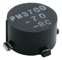
PM3700-20-RC
Choke, Common Mode, 500 µH, PM3700 Series, 6 A, 17.78mm x 11.43mm
⚠️ Reference pricing provided. In case of supply shortages, we will connect you with our trusted procurement partners to ensure your project's continuity.
- Manufacturer: BOURNS JW MILLER
- Product type: SMD Common Mode Chokes / Filters
- Rated Current:6A; Inductance:500µH; Product Range:PM3700 Series; Impedance:-; Common Mode Filter Case:17.78mm x 11.43mm; Automotive Qualification Standard:-; SVHC:No SVHC (15-Jan-2018); Cor
- SVHC: No SVHC (04-Feb-2026)
- Impedance: -
- Inductance: 500µH
- Product Range: PM3700 Series
- Product Width: 11.43mm
- Qualification: -
- Product Height: 0mm
- Product Length: 17.78mm
- DC Current Rating: 6A
- DC Resistance Max: 0.01ohm
- Common Mode Filter Case: 17.78mm x 11.43mm
- Inductor Case / Package: -
- Operating Temperature Max: 125°C
- Operating Temperature Min: -55°C
| Delivery and price | |
|---|---|
| Units per pack | 200 |
| Price | 1.47 € |
| Current stock | 50+ |
| Lead time | 30 days |
Datasheet

## **Features**

■ Formerly                         model J. W. Miller’

- Current rating up to 7 A

## **Applications**

■ Filtering

   - Common mode

- Compact size

- Tape and reel packaging

- RoHS compliant*

## **PM3700 Series - SMD Common Mode Choke** BOURNS [iy

**Inductance mH Min. DCR Leakage Typical Frequency @ 1 kHz / Part (** Ω **) Irms Inductance Range with Bourns Part No. 50 mV Marking Max. (A) (** μ **H) Typ. 20 dB Atten.** ~~po~~ PM3700-10-RC 0.2 201 0.008 7.0 1.6 5 - 55 MHz ~~se~~ PM3700-20-RC 0.5 501 0.010 6.0 2.2 4 - 40 MHz PM3700-30-RC 0.75 751 0.012 5.5 2.9 1 - 20 MHz ~~|~~ PM3700-40-RC 1.0 102 0.020 4.0 3.9 500 KHz - 40 MHz PM3700-50-RC 2.0 202 0.030 3.5 0.3 300 KHz - 20 MHz ~~es ee se~~ PM3700-60-RC 5.0 502 0.070 2.0 0.4 100 KHz - 10 MHz PM3700-70-RC 10 103 0.150 1.5 0.5 50 KHz - 5 MHz ~~Rs eG de ss~~ PM3700-80-RC 20 203 ~~eG~~ 0.250 1.0 0.7 25 KHz - 4 MHz

Temperature Rise ... 35 °C typical at Irms Operating Temperature ..-55 °C to +125 °C Storage Temperature ................................-55 °C to +125 °C Soldering ..........245 °C, 5 seconds max. Dielectric Strength ...................500 Vrms between windings Moisture Sensitivity Level .....................1 ................. N/A

## ~~**Materials**~~

Core ..............................................Ferrite Wire ................. Polyester-coated copper Terminal Coating............. Sn-Ag-Cu alloy Packaging ........200 pcs. per 13-inch reel

## ~~**Schematic**~~

## ~~**Product Dimensions**~~

**==> picture [29 x 104] intentionally omitted <==**

**----- Start of picture text -----**<br>
3 2<br>Il<br>Il<br>e<br>4 1<br>**----- End of picture text -----**<br>


**==> picture [469 x 368] intentionally omitted <==**

**----- Start of picture text -----**<br>
21.6 ± 0.3<br>(0.850 ± 0.012)<br>3<br>Il a (0.157)4.0<br>TYP.<br>Il<br>e e<br>4 XXX 2<br>4 1 SEE ‘PART<br>MARKING’ COLUMN<br>OF ELECTRICAL<br>SPECIFICATIONS<br>7 | 1.91<br>Profile POLARITYMARK Sf 1 — (0.075)<br>Temperature 17.78<br>Rising Area Preheat Area Reflow Area Forced Cooling Area (0.70)<br>±4.0 °C/sec. max. 150 ~ 200 °C / 60 - 120 sec. +3.0 °C/sec. max. 1.0~5.0 °C/sec. max.<br>PeakTemperature:<br>250 —~——4——~—-| — ——— 4 — jo e 250 °C — — —<br>| | i\ AZ<br>200 ~ - -+- - --- s 5ff ] NEI 60~150 sec.max. N 217 °C | a l s el— 11.43<br>||]| (0.45)MAX.<br>150<br>60~120 sec.max. 60 sec.max. | |   Recommended Pad Layout<br>100 3.18 3.18<br>_ f-— Fo Ee EL (0.125) ! | (0.125)<br>50<br>I 7 - —-— | - +--- -| l-- - —-1 | - --4 |- --- b L | es aee ee<br>| | | | | +<br>0 50 100 150 200 250<br>Time (Seconds)<br>Peak Temperature: 245 ° ±5 °C max., 30 sec. max.<br>LI] a<br>Maximum Time Above 217 °C: 60~150 seconds<br>21.59<br>(0.850)<br>WARNING  Cancer and Reproductive Harm - www.P65Warnings.ca.gov —e 21.59<br>(0.850)<br>C)<br>°( er<br>utare<br>p<br>m<br>e<br>T<br>**----- End of picture text -----**<br>


## **WARNING  Cancer and Reproductive Harm -** www.P65Warnings.ca.gov

* RoHS Directive 2002/95/EC Jan. 27, 2003 including annex and RoHS Recast 2011/65/EU June 8, 2011. Specifications are subject to change without notice. Users should verify actual device performance in their specific applications. The products described herein and this document are subject to specific legal disclaimers as set forth on the last page of this document, and at www.bourns.com/docs/legal/disclaimer.pdf

**==> picture [76 x 16] intentionally omitted <==**

**----- Start of picture text -----**<br>
MM<br>DIMENSIONS:<br>(INCHES)<br>**----- End of picture text -----**<br>


®

## **Legal Disclaimer Notice**

This legal disclaimer applies to purchasers and users of Bourns[®] products manufactured by or on behalf of Bourns, Inc. and

Unless otherwise expressly indicated in writing, Bourns[®] products and data sheets relating thereto are subject to change without notice. Users should check for and obtain the latest relevant information and verify that such information is and complete before placing orders for Bourns[®] products.

The characteristics and parameters of a Bourns[®] product set forth in its data sheet are based on laboratory conditions, and statements regarding the suitability of products for certain types of applications are based on Bourns’ knowledge of typical requirements in generic applications.  The characteristics and parameters of a Bourns[®] product in a user application may

® product with other components ®

the actual performance of the Bourns[®]

Unless Bourns has explicitly designated an individual Bourns ® product as meeting the requirements of a particular industry standard (e.g., ISO/TS 16949) or a particular qualification (e.g., UL listed or recognized), Bourns is not responsible for any failure of an individual Bourns ® product to meet the requirements of such industry standard or particular qualification. Users of Bourns[®] products are responsible for ensuring compliance with safety-related requirements and standards applicable to

Bourns[®]

on a case-by-case basis, use of any Bourns[®]

®

**==> picture [5 x 5] intentionally omitted <==**

**----- Start of picture text -----**<br>
®<br>**----- End of picture text -----**<br>


®

Bourns[®]

® standard products that are suitable for use in aircraft “Applications.” Unless expressly and specifically ® standard

the user’s sole risk.

The use and level of testing applicable to Bourns ® custom products shall be negotiated on a case-by-case basis by Bourns and the user for which such Bourns[®] custom products are specially designed. Absent a written agreement between Bourns and the user regarding the use and level of such testing, the above provisions applicable to Bourns ® standard products shall also apply to such Bourns[®] custom products.

Users shall not sell, transfer, export or re-export any Bourns[®] design, development, production, use or stockpiling of Bourns[®]

regulations. Further, Bourns ® products and Bourns technology and technical data may not under any circumstance be exported or re-exported to countries subject to international sanctions or embargoes.  Bourns[®] products may not, without

_bilingual versions are available at:_

_Web Page: http://www.bourns.com/legal/disclaimers-terms-and-policies PDF: http://www.bourns.com/docs/Legal/disclaimer.pdf_

**==> picture [471 x 474] intentionally omitted <==**

**----- Start of picture text -----**<br>
PM3700 Series - SMD Common Mode Choke<br>2.00 ± 0.10<br>(.079 ± .004) 4.00 ± 0.10<br>(.069 ± .004)1.75 ± 0.10 POLARITYMARK (.157 ± .004) DIA. (.079)2.00 [MIN.] DIA.(.059 +.004/-.000)1.50 +0.10/-0.00 0.40 ± 0.05<br>sl iT i (.016 ± .002)<br>20.20 ± 0.10<br>(.795 ± .004)<br>5 ° MAX. 11.60 ± 0.10<br>40.40 ± 0.20 (.457 ± .004)<br>(1.590 ± .008)<br>5.9<br>44.00 ± 0.30 10 ° (.232)<br>(1.732 ± .012) ORS Me<br>4.0<br>(.157)<br>11.60 ± 0.10<br>28.00 ± 0.10 (.457 ± .004)<br>(1.102 ± .004)<br>USER DIRECTION OF FEED<br>25.52<br>QTY: 200 PCS. PER REEL (1.005)<br>10 °<br>11.60 ± 0.10<br>4.0 4 (.457 ± .004)<br>_ |--_—- (.157) —<br>5.9<br>PS<br>(.232)<br>22.10 ± 0.10<br>aan (.870 ± .004)<br>330 2.0 ± 0.5 50.4<br>(12.99) es [DIA.] (.079 ± .020) | -— (1.984) THICKNESS<br>0.10<br>13.0 ± 0.5 (.004)<br>(.827 21.0 ±± .031) 0.8 (.512 ± .020)DIA. MAX.<br>EMBOSSED<br>CAVITY<br>50.0<br>(1.969)<br>13.0 ± 0.5<br>(.512 ± .020)  TS A [DIA.] Sl ot Q EMBOSSED<br>CARRIER<br>y)<br>Gat 46.0<br>(1.811)<br>MM<br>DIMENSIONS:<br>(INCHES)<br>201 201<br>**----- End of picture text -----**<br>


Tel: +886-2 2562-4117 • Email: asiacus@bourns.com **EMEA:** Tel: +36 88 520 390 • Email: eurocus@bourns.com

**The Americas:** Tel: +1-951 781-5500 • Email: americus@bourns.com **www.bourns.com**

REV. 09/17

Specifications are subject to change without notice. Users should verify actual device performance in their specific applications.

The products described herein and this document are subject to specific legal disclaimers as set forth on the last page of this document, and at www.bourns.com/docs/legal/disclaimer.pdf.
Updated at June 5, 2026
About Novapart
Novapart is a B2B electronic component broker specialising in stock shortages and cost reduction. We source hard-to-find parts and identify compliant alternatives across a catalogue of 410,000+ components from 500+ manufacturers.
Learn more →Stock Shortage Specialist
When a component is unavailable, discontinued or has an unacceptable lead time, we tap into our network of vetted European and Asian distributors to source what you need — without compromising on quality or traceability.
Request a quote →Compliant Alternatives
We identify pin-to-pin, electrically equivalent substitutes that meet the same certifications (RoHS, AEC-Q100, REACH) as your original specification — validated against datasheets, not just part numbers. Often at a lower cost.
BOM Analysis service →