
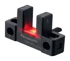


PM-L45-P
Photoelectric Sensor, Micro, U-Shape, L Type, 6 mm, PNP Open Collector, 5 V to 24 V, PM-45 Series
- Manufacturer: PANASONIC
- Product type:
- SVHC: To Be Advised
- IP Rating: IP64
- Output Type: PNP Open Collector
- Sensor Type: Micro Photoelectric Sensor
- Light Source: 855nm Infrared LED
- Product Range: PM-45 Series
- Qualification: -
- Sensing Method: Through Beam
- Connection Method: Cable
- Sensing Range Max: 6mm
- Sensor Output Type: PNP Open Collector
- Supply Voltage Max: 24VDC
- Supply Voltage Min: 5VDC
- Sensing Distance Max: 6mm
- Supply Voltage DC Max: 24V
- Supply Voltage DC Min: 5V
- Operating Temperature Max: 55°C
- Operating Temperature Min: -25°C
| Delivery and price | |
|---|---|
| Units per pack | 100 |
| Price | 9.46 € |
| Current stock | 10+ |
| Lead time | 30 days |
395 U-shaped Micro Photoelectric Sensor Amplifier Built-in al **PM-25 SERIES PM-45 SERIES PM-65 SERIES ■** General terms and conditions ............. F-3 **■** Selection guide ............................. P.393~ FIBER Related Information SENSORS **■** Glossary of terms / General precautions ......P.1549~ / P.1552~ **■** Korea’s S-mark .............................. P.1602 LASER SENSORS PHOTOELECTRIC SENSORS Recognition MICRO PHOTOELECTRIC SENSORS AREA Certified SENSORS (Some models only) SAFETY LIGHT CURTAINS / SAFETY COMPONENTS PRESSURE / ~~=~~ FLOW SENSORS INDUCTIVE PROXIMITY SENSORS PARTICULAR USE SENSORS SENSOR OPTIONS SIMPLE WIRE-SAVING UNITS WIRE-SAVING SYSTEMS MEASUREMENT SENSORS ~~an~~ **panasonic.net/id/pidsx/global** PNP output type available STATIC CONTROL DEVICES LASER MARKERS

PLC HUMAN MACHINE INTERFACES ENERGY MANAGEMENT SOLUTIONS FA COMPONENTS MACHINE VISION SYSTEMS UV CURING SYSTEMS

Selection Guide U-shaped Convergent Reflective **PM-25/PM-45/ PM-65**

## **One step ahead in performance and mounting ease**

## **Three protection circuits standard on all models PM-25/45/65 SERIES**

All models are standardly equipped with the following protection circuits in their compact bodies. These protection circuits minimize the possibility of sensor malfunctions caused by erroneous wiring.

**Industry’s first*!  IP64 rating** *As of April 2017, in-company survey.

## **PM-25/45 SERIES**

Our original integrated molding method has eliminated grooves and gaps on the sensing surface and main body, thus reducing the possibility of malfunctions caused by splashing water or dust.

> 1 Reverse supply polarity protection circuit

> 2 Reverse output polarity protection circuit

> 3 Output short-circuit protection circuit

## **Ample beam emitting / receiving distance of 6 mm 0.236 in PM-25/45/65 SERIES**

The beam emitting and receiving sections are 0.5 mm 0.02 in thinner than those on our conventional models while their external dimensions are the same. As a result, the distance between the beam emitting point and receiving point increased by 1 mm 0.039 in. The wider distance means less possibility of collision between the sensing section and sensing object.

**==> picture [209 x 33] intentionally omitted <==**

**----- Start of picture text -----**<br>
No ridges on<br>sensing surface<br>No joint seam<br>**----- End of picture text -----**<br>


## **Beam marks for easy adjustment**

## **PM-25/45/65 SERIES**

> 13.4 **6 0.236** 0.528 3.7 0.146 The upper-limit and lower-limit positions of beam can be visually confirmed from the front, back, right and left sides of the sensor unit. This allows easy adjustment of the position of sensing object.

> Upper-limit position Beam width of beam axis Lower-limit position Beam width marks are provided on

> of beam axis **PM25 series** and **PM45 series** . (Unit: mm in) ~~ae~~ | < Front / back > < Right / left >

U-shaped Micro Photoelectric Sensor **PM-25 SERIES  PM-45 SERIES  PM-65 SERIES**

396

FIBER SENSORS LASER SENSORS PHOTOELECTRIC SENSORS MICRO PHOTOELECTRIC SENSORS AREA SENSORS SAFETY LIGHT CURTAINS / SAFETY COMPONENTS PRESSURE / FLOW SENSORS INDUCTIVE PROXIMITY SENSORS PARTICULAR USE SENSORS

SENSOR OPTIONS SIMPLE WIRE-SAVING UNITS WIRE-SAVING SYSTEMS MEASUREMENT SENSORS STATIC CONTROL DEVICES LASER MARKERS PLC

HUMAN MACHINE INTERFACES ENERGY MANAGEMENT SOLUTIONS FA COMPONENTS MACHINE VISION SYSTEMS UV CURING SYSTEMS

Selection Guide U-shaped Convergent Reflective

**PM-25/PM-45/ PM-65**

**==> picture [502 x 13] intentionally omitted <==**

**----- Start of picture text -----**<br>
ee APPLICATIONS<br>**----- End of picture text -----**<br>


**==> picture [488 x 134] intentionally omitted <==**

**----- Start of picture text -----**<br>
Positioning of a pallet Sensing the starting point and overrun  Sensing the starting point on a<br>of a moving body rotating body<br>Overrun sensing<br>Dog Starting<br>i y point<br>The starting<br>point can be<br>sensed by<br>making a slit in<br>Starting point sensing the rotating<br>body.<br>Overrun<br>sensing<br>Starting point and overrun is<br>Pallet is stopped by sensing the dog*. sensed using the dog* on the base.<br>**----- End of picture text -----**<br>


- “Dog” refers to the sensing object for activating the sensor’s detecting operation.

## **Large and easy to see Multi-angle operation indicator**

## **VARIATION**

## **PM-25/45/65 SERIES**

Sensors come in various shapes to suit a wide range of mounting conditions

The large operation indicator (orange) lights up when the beam enters. The indicator is easy to see from above and from the sides.

## **PM-25 SERIES**

## **Ultra-small / Cable type**

Easy mounting with M2/M3 screws!

## **PM-45 SERIES**

## **Compact size**

All new models require significantly less mounting space than our conventional models when mounted with the same pitch. What’s more, the new models can directly replace our conventional models currently in use.

NPN output 1 m 3.281 ft cable 3 m 9.843 ft cable 1 m resistant cable3.281 ft bendingPNP output 1 m 3.281 ft cable 3 m 9.843 ft cable 1 m 3.281 ft bending-resistant cable ~~=—=—_ &~~~ **Compact / Cable type PM-45 SERIES** Compact size!

**==> picture [473 x 107] intentionally omitted <==**

**----- Start of picture text -----**<br>
PM-L45 Conventional<br>model  Compact size!<br>(L type)<br>14.6 0.575 15.5 0.610 NPN output 1 m 3.281 ft cable 3 m 9.843 ft cable 1 m 3.281 ft bending-resistant cable<br>26 1.024 10 PNP output 1 m 3.281 ft cable 3 m 9.843 ft cable 1 m 3.281 ft bending-resistant cable<br> 0.394 26 1.024 18.5 0.728<br>< A So a<br>(Unit: mm in)<br>Compact / Connector built-in typepact / Connector built-in typeact / Connector built-in typeypee<br>All models easy to   Easy connection with a single touch using commercially-<br>**----- End of picture text -----**<br>


**Compact / Connector built-in typepact / Connector built-in typeact / Connector built-in typeypee PM-65 SERIES**

Easy connection with a single touch using commerciallyavailable connectors

## **PM-25/45/65 SERIES**

## **mount with M3 screws**

Connector attached cable Connector attached bending-resistant cable ~~ee~~ NPN output 3 m 1 m 9.843 ft3.281 ft, 5 m , 2 m 16.404 ft6.562 ft, 3 m 1 m 9.843 ft3.281 ft, 5 m , 2 m 16.404 ft6.562 ft, Connector attached cable Connector attached bending-resistant cable ~~SS~~ PNP output 3 m 1 m 9.843 ft3.281 ft, 5 m , 2 m 16.404 ft6.562 ft, 3 m 1 m 9.843 ft3.281 ft, 5 m , 2 m 16.404 ft6.562 ft,

The sensor unit can be installed with one or two M3 screws.

- M3 screws and washers are not included.

- Models requiring one M3 screw for installation **PM-F25** , **PM-R25** , **PM-F65** , **PM-R65**

- Models requiring two M3 screws for installation Models other than above

## **Resistant to vibrations**

## **and impacts**

## **PM-25/45/65 SERIES**

The sections where stress concentrates, such as the connecting section of the cable and internal circuit, are covered with a resin. This helps prevent malfunctions caused by vibrations and impacts.

Resin-filled structure (cross-sectional view)

U-shaped Micro Photoelectric Sensor **PM-25 SERIES  PM-45 SERIES  PM-65 SERIES**

397

## Ultra-small / Cable type **PM-25 SERIES**

|Type|Type|Appearance (mmin)<br>~~a~~|Sensing range<br>~~ee~~|Model No.<br>~~ee~~<br>~~ee~~|Cable length<br>~~eee~~|Output<br>~~ee~~|Output operation|
|---|---|---|---|---|---|---|---|
|Ultra-small / Cable type<br> ||<br>~~a~~<br>~~|~~<br>~~=)~~|K type<br>||<br>~~a~~|60.236<br>23.9<br>0.941<br>12.3<br>0.484<br>~~a~~<br>||~~S~~e~~s ~~<br>~~a~~|6 mm0.236 in<br>(fixed)<br>~~ee~~<br> <br>~~——~~|**PM-K25**<br>~~ee~~<br>~~ee~~<br>~~es~~<br>~~a~~|1 m3.281 ft<br>~~eee ~~<br>~~a~~|NPN open-collector<br>transistor<br> ~~ee~~|Incorporated with 2 outputs:<br>Light-ON/Dark-ON|
|||||**PM-K25-R**<br>~~ee~~<br>~~es~~<br>~~a~~|1 m3.281 ft,<br>bending-resistant cable<br>~~a~~|||
|||||**PM-K25-C3**<br>~~es~~<br>~~es~~<br>~~a~~|3 m9.843 ft<br>~~ee~~<br>~~a~~|||
|||||**PM-K25-P**<br>~~es~~<br> ~~a~~|1 m3.281 ft<br>~~ee~~<br>~~a~~|PNP open-collector<br>transistor||
||L type<br>~~|e~~|13.4<br>0.528<br>120.472<br>12<br>0.472<br>~~e~~||**PM-L25**<br>~~es ~~<br>~~—+-——~~<br>~~——~~|1 m3.281 ft<br> ~~ee~~<br>~~—+-——~~<br>~~——~~|NPN open-collector<br>transistor<br>~~po~~||
|||||**PM-L25-R**<br>~~—+-——~~<br>~~——~~|1 m3.281 ft,<br>bending-resistant cable<br>~~—+-——~~<br>~~——~~|||
|||||**PM-L25-C3**<br>~~—+-——~~<br>~~po~~<br>~~——~~|3 m9.843 ft<br>~~—+-——~~<br>~~po~~<br>~~——~~|||
|||||**PM-L25-P**<br>~~po~~|1 m3.281 ft<br>~~po~~|PNP open-collector<br>transistor<br>~~po~~||
||U type<br>~~=)~~|60.236<br>16<br>0.630<br>13.4<br>0.528<br>a~~e~~<br>~~=)~~||**PM-U25**<br>~~——~~|1 m3.281 ft|NPN open-collector<br>transistor||
|||||**PM-U25-R**<br>~~——~~|1 m3.281 ft,<br>bending-resistant cable|||
|||||**PM-U25-C3**<br>~~es~~<br>~~——~~|3 m9.843 ft<br>~~ee~~|||
|||||**PM-U25-P**<br>~~es~~<br>~~——~~<br>~~—--——~~|1 m3.281 ft<br>~~ee~~<br>~~—--——~~|PNP open-collector<br>transistor||
||F type|11.70.461<br>12.5<br>0.492<br>13.4<br>0.528<br>~~-~~||**PM-F25**<br>~~es ~~<br>~~—--——~~|1 m3.281 ft<br> ~~ee~~<br>~~—--——~~|NPN open-collector<br>transistor<br>~~——-——}——~~||
|||||**PM-F25-R**<br>~~—--——~~<br>~~——-——}~~|1 m3.281 ft,<br>bending-resistant cable<br>~~—--——~~<br>~~——-——}~~|||
|||||**PM-F25-C3**<br>~~—--——~~<br>~~——-——}~~|3 m9.843 ft<br>~~—--——~~<br>~~——-——}~~|||
|||||**PM-F25-P**<br>~~——-——}~~|1 m3.281 ft<br>~~——-——}~~|PNP open-collector<br>transistor<br>~~——-——}——~~||
||R type|11.70.461<br>12.5<br>0.492<br>13.4<br>0.528<br>~~-~~<br>~~S~~S||**PM-R25**<br>~~——-——}~~|1 m3.281 ft<br>~~——-——}~~|NPN open-collector<br>transistor<br>~~——-——}——~~||
|||||**PM-R25-R**|1 m3.281 ft,<br>bending-resistant cable|||
|||||**PM-R25-C3**|3 m9.843 ft|||
|||||**PM-R25-P**|1 m3.281 ft|PNP open-collector<br>transistor||


Note: The suffix “ **-R** ” in the model No. indicates a bending-resistant cable type. The suffix “ **-C3** ” indicates a 3 m 9.843 ft cable length type.

## **OPTIONS**

## **Mounting screw**

|Designation<br>Model No.|Model No.|Description|
|---|---|---|
|Mounting screw|**MS-M2**|Mounting screw with washers for the ultra-small type sensor<br>(50 pcs. lot). It can mount securely as it is spring washer attached.|


**• MS-M2**

M2 (length 10 mm 0.394 in) screw

with a spring washer

U-shaped Micro Photoelectric Sensor **PM-25 SERIES  PM-45 SERIES  PM-65 SERIES**

398

FIBER SENSORS LASER SENSORS PHOTOELECTRIC SENSORS MICRO PHOTOELECTRIC SENSORS AREA SENSORS SAFETY LIGHT CURTAINS / SAFETY COMPONENTS PRESSURE / FLOW SENSORS INDUCTIVE PROXIMITY SENSORS PARTICULAR USE SENSORS SENSOR OPTIONS SIMPLE WIRE-SAVING UNITS WIRE-SAVING SYSTEMS MEASUREMENT SENSORS STATIC CONTROL DEVICES LASER MARKERS PLC

HUMAN MACHINE INTERFACES ENERGY MANAGEMENT SOLUTIONS FA COMPONENTS MACHINE VISION SYSTEMS UV CURING SYSTEMS

Selection Guide U-shaped Convergent Reflective

**PM-25/PM-45/ PM-65**

## **SPECIFICATIONS**

**==> picture [504 x 515] intentionally omitted <==**

**----- Start of picture text -----**<br>
Ultra-small / Cable type<br>Type<br>Bending-resistant cable 3 m 9.843 ft cable<br>NPN output PM- □ 25 PM- □ 25-R PM- □ 25-C3<br>Item PNP output PM- □ 25-P ― ―<br>CE marking directive compliance EMC Directive, RoHS Directive<br>Sensing range 6 mm 0.236 in (fixed)<br>Minimum sensing object 0.8 × 1.2 mm 0.031 × 0.047 in opaque object<br>Hysteresis 0.05 mm 0.002 in or less<br>Repeatability 0.01 mm 0.0004 in or less<br>Supply voltage 5 to 24 V DC ±10 % Ripple P-P 10 % or less<br>Current consumption 15 mA or less<br><NPN output type> <PNP output type><br>NPN open-collector transistor PNP open-collector transistor<br>• Maximum sink current: 50 mA • Maximum source current: 50 mA<br>Output • Applied voltage: 30 V DC or less (between output and 0 V) • Applied voltage: 30 V DC or less (between output and +V)<br>• Residual voltage:  2 V or less (at 50 mA sink current)  • Residual voltage:  2 V or less (at 50 mA source current)<br>1 V or less (at 16 mA sink current) 1 V or less (at 16 mA source current)<br>Output operation Incorporated with 2 outputs: Light-ON/Dark-ON<br>Short-circuit protection Incorporated<br>Under light received condition: 20 μs or less<br>Response time Under light interrupted condition: 80 μs or less<br>(Maximum response frequency: 3 kHz) (Note 2)<br>Operation indicator Orange LED (lights up under light received condition)<br>Pollution degree 3<br>Protection IP64 (IEC)<br>Ambient temperature  –25 to +55 °C –13 to +131 °F (No dew condensation or icing allowed), Storage: –30 to +80 °C –22 to +176 °F<br>(Note 3, 4)<br>Ambient humidity 5 to 85 % RH, Storage: 5 to 95 % RH<br>Ambient illuminance Fluorescent light: 1,000 ℓx or less at the light-receiving face<br>Voltage withstandability 1,000 V AC for one min. between all supply terminals connected together and enclosure<br>Insulation resistance 20 MΩ, or more, with 250 V DC megger between all supply terminals connected together and enclosure<br>Vibration resistance 10 to 2,000 Hz frequency, 1.5 mm 0.059 in double amplitude (maximum acceleration 196 m/s [2] ) in X, Y and Z directions for two hours each<br>Shock resistance 15,000 m/s [2]  acceleration (1,500 G approx.) in X, Y and Z directions three times each<br>Emitting element Infrared LED (Peak emission wavelength: 855 nm 0.034 mil, non-modulated)<br>Material Enclosure: PBT, Display section: Polycarbonate<br>Cable 0.09 mm [2]  4-core cabtyre cable, PVC,  0.1 mm [2]  4-core bending-resistant cabtyre  0.09 mm [2]  4-core cabtyre cable, PVC,<br>1 m 3.281 ft long cable, PVC, 1 m 3.281 ft long (Note 5, 6) 3 m 9.843 ft long<br>Cable extension Extension up to total 100 m 328.084 ft is possible with 0.3 mm [2] , or more, cable.  (Note 7)<br>Net weight: 30 g approx.,<br>Weight Net weight: 10 g approx., Gross weight: 15 g approx.<br>Gross weight: 35 g approx.<br>Model No.<br>Environmental resistance<br>**----- End of picture text -----**<br>


Notes:  1) Where measurement conditions have not been specified precisely, the conditions used were an ambient temperature of +23 °C +73.4 °F.

- 2) The response frequency is the value when the disc, given in the figure below, is rotated.

**==> picture [253 x 67] intentionally omitted <==**

**----- Start of picture text -----**<br>
Disc 1.8 mm 0.071 in<br>Disc<br>t = 0.2 mm 0.008 in<br>1.6 mm 0.063 in 1.6 mm 0.063 in<br>**----- End of picture text -----**<br>


- 3) In case the **PM-25** series is used at an ambient temperature of +50 °C +122 °F, or more, make sure to mount it on a metal body.

- 4) Note that the cable of **PM-□25-R** loses its flexibility when the ambient temperature decreases to about -10 °C +14 F°.

- 5)  The cable of **PM-□25-R** is a bending-resistant cable usable on a moving base. When the sensor is mounted on a moving base, secure the sensor cable joint at the unit in place so that stress is not applied to it.

- 6) When storing **PM-□25-R** , make sure that the cable does not come into contact with the sensing section or operation indicator.

7) If the cable is extended to 20 m 65.617 ft or longer, confirm that the supply voltage at the end of the cable attached to the sensor is 4.5 V or higher.

U-shaped Micro Photoelectric Sensor **PM-25 SERIES  PM-45 SERIES  PM-65 SERIES**

399

LASER **Compact size!** SENSORS ELECTRICPHOTOCable type SENSORS MICRO Built-in connector PHOTOELECTRIC ~~=~~ SENSORS ~~ee]~~ AREA SENSORS SAFETY LIGHT CURTAINS / SAFETY **PM-K45** COMPONENTS PRESSURE / FLOW SENSORS INDUCTIVE ~~a~~ PROXIMITYSENSORS ~~—_~~ PARTICULAR USE SENSORS

## ~~r~~ FIBER Compact / Cable type **PM-45 SERIES** ~~rr~~ SENSORS

|Type|Type|Appearance (mmin)|Sensing range|Model No.|Cable length|Output|Output operation|
|---|---|---|---|---|---|---|---|
|Compact / Cable type<br> ||<br> **||**<br> ~~||~~<br>~~=~~|K type<br>|||21.3<br>0.839<br>70.276<br>25.4<br>1.000<br>|| s~~e~~ga, <br>~~a~~|6 mm0.236 in<br>(fixed)<br> <br> <br> <br> <br> <br>~~=~~<br>~~a~~|**PM-K45**<br>~~es~~<br>~~Fs~~|1 m3.281 ft<br>~~es~~<br>~~Fs~~|NPN open-collector<br>transistor<br>~~Fs~~|Incorporated with 2 outputs:<br>Light-ON/Dark-ON<br>~~a~~<br>~~a~~|
|||||**PM-K45-C3**<br>~~es~~<br>~~Fs~~|3 m9.843 ft<br>~~es~~<br>~~Fs~~|||
|||||**PM-K45-P**<br> ~~Fs~~<br>~~a~~|1 m3.281 ft<br>~~Fs~~<br>~~a~~|PNP open-collector<br>transistor<br>~~Fs~~<br>~~a~~||
|||||**PM-K45-P-C3**<br>~~a~~<br>~~es~~|3 m9.843 ft<br>~~a~~<br>~~es~~|||
||T type<br>**||**|13.70.539<br>18.1<br>0.713<br>26<br>1.024<br>~~a ~~<br>>. <br>~~<~~“S~~*~~<br>**||**&||**PM-T45**<br> ~~a~~<br>~~es~~<br>~~a~~|1 m3.281 ft<br>~~a~~<br>~~es~~<br>~~a~~|NPN open-collector<br>transistor<br>~~a~~<br>~~a~~||
|||||**PM-T45-C3**<br> ~~a~~<br>~~ee~~|3 m9.843 ft<br>~~a~~<br>~~ee~~|||
|||||**PM-T45-P**<br>~~ee~~<br>~~fr~~|1 m3.281 ft<br>~~ee~~<br>~~fr~~|PNP open-collector<br>transistor<br>~~fr~~<br>~~—r—~~||
|||||**PM-T45-P-C3**<br>~~ee~~<br>~~fr~~<br>~~a~~<br>~~—r~~|3 m9.843 ft<br>~~ee~~<br>~~fr~~<br>~~a~~<br>~~—r~~|||
||L type<br>**||**<br>||70.276<br>14.60.575<br>26<br>1.024<br>**||** &<br>~~i~~t<br>| ~~<~~a~~,~~||**PM-L45**<br>~~fr~~<br>~~a~~<br>~~—r~~<br>~~a~~|1 m3.281 ft<br>~~fr~~<br>~~a~~<br>~~—r~~<br>~~a~~|NPN open-collector<br>transistor<br>~~fr~~<br>~~—r—~~<br>~~rn~~||
|||||**PM-L45-C3**<br>~~—r~~<br>~~a~~<br>~~rn~~|3 m9.843 ft<br>~~—r~~<br>~~a~~<br>~~rn~~|||
|||||**PM-L45-P**<br>~~—r~~<br>~~a~~<br>~~rn~~|1 m3.281 ft<br>~~—r~~<br>~~a~~<br>~~rn~~|PNP open-collector<br>transistor<br>~~—r—~~<br>~~rn~~||
|||||**PM-L45-P-C3**<br>~~rn~~<br>~~a~~|3 m9.843 ft<br>~~rn~~<br>~~a~~|||
||Y type<br>~~||~~|20.6<br>0.811<br>14.60.575<br>13.4<br>0.528<br>aa <br>ite~~,~~<br>~~|| ~ex~~||**PM-Y45**<br>~~a~~<br>~~ee~~<br>|1 m3.281 ft<br>~~a~~<br>~~ee~~<br>|NPN open-collector<br>transistor<br>~~a~~<br>~~**a**~~||
|||||**PM-Y45-C3**<br> ~~a~~<br>~~ee~~<br>~~**a**~~|3 m9.843 ft<br>~~a~~<br>~~ee~~<br>~~**a**~~|||
|||||**PM-Y45-P**<br>~~ee~~<br>~~**a**~~|1 m3.281 ft<br>~~ee~~<br>~~**a**~~|PNP open-collector<br>transistor<br>~~**a**~~||
|||||**PM-Y45-P-C3**<br>~~**a**~~|3 m9.843 ft<br>~~**a**~~|||
||F type<br>~~||~~<br>|<br>~~=~~|130.512<br>21.3<br>0.839<br>13.7<br>0.539<br>~~|| ~ex ~~<br>|<br>~~|~~<br>~~=~~||**PM-F45**<br> ~~**a**~~<br>~~a~~|1 m3.281 ft<br>~~**a**~~<br>~~a~~|NPN open-collector<br>transistor<br>~~**a**~~||
|||||**PM-F45-C3**<br>~~a~~|3 m9.843 ft<br>~~a~~|||
|||||**PM-F45-P**<br>~~a~~<br>~~—r~~|1 m3.281 ft<br>~~a~~<br>~~—r~~|PNP open-collector<br>transistor<br>~~—r~~<br>~~a~~||
|||||**PM-F45-P-C3**<br>~~—r~~<br>~~=~~<br>~~a~~|3 m9.843 ft<br>~~—r~~<br>~~=~~<br>~~a~~|||
||R type<br>~~=~~|13.7<br>0.539<br>130.512<br>21.3<br>0.839<br>~~=~~<br>~~a~~<br>~~G~~E~~.~~<br>~~o~~s||**PM-R45**<br>~~=~~<br>~~a~~<br>~~a~~|1 m3.281 ft<br>~~=~~<br>~~a~~<br>~~a~~|NPN open-collector<br>transistor<br>~~a~~<br>~~a~~||
|||||**PM-R45-C3**<br>~~a~~<br>~~a~~<br>~~—~~|3 m9.843 ft<br>~~a~~<br>~~a~~<br>~~—~~|||
|||||**PM-R45-P**<br>~~a~~<br>~~—~~<br>~~**a**~~|1 m3.281 ft<br>~~a~~<br>~~—~~<br>~~**a**~~|PNP open-collector<br>transistor<br>~~a~~<br>~~**a**~~||
|||||**PM-R45-P-C3**<br>~~—~~<br>~~**a**~~|3 m9.843 ft<br>~~—~~<br>~~**a**~~|||


U-shaped Micro Photoelectric Sensor **PM-25 SERIES  PM-45 SERIES  PM-65 SERIES**

400

FIBER SENSORS

LASER SENSORS PHOTOELECTRIC SENSORS MICRO PHOTOELECTRIC SENSORS AREA SENSORS SAFETY LIGHT CURTAINS / SAFETY COMPONENTS PRESSURE / FLOW SENSORS INDUCTIVE PROXIMITY SENSORS PARTICULAR USE SENSORS

SENSOR OPTIONS

SIMPLE WIRE-SAVING UNITS WIRE-SAVING SYSTEMS MEASUREMENT SENSORS STATIC CONTROL DEVICES LASER MARKERS PLC

HUMAN MACHINE INTERFACES ENERGY MANAGEMENT SOLUTIONS FA COMPONENTS MACHINE VISION SYSTEMS UV CURING SYSTEMS

Selection Guide U-shaped Convergent Reflective

**PM-25/PM-45/ PM-65**

**==> picture [504 x 517] intentionally omitted <==**

**----- Start of picture text -----**<br>
SPECIFICATIONS<br>Compact / Cable type<br>Type<br>3 m 9.843 ft cable<br>NPN output PM- □ 45 PM- □ 45-C3<br>Item PNP output PM- □ 45-P PM- □ 45-P-C3<br>CE marking directive compliance EMC Directive, RoHS Directive<br>Sensing range 6 mm 0.236 in (fixed)<br>Minimum sensing object 0.8 × 1.2 mm 0.031 × 0.047 in opaque object<br>Hysteresis 0.05 mm 0.002 in or less<br>Repeatability 0.01 mm 0.0004 in or less<br>Supply voltage 5 to 24 V DC ±10 % Ripple P-P 10 % or less<br>Current consumption 15 mA or less<br><NPN output type> <PNP output type><br>NPN open-collector transistor PNP open-collector transistor<br>• Maximum sink current: 50 mA • Maximum source current: 50 mA<br>Output • Applied voltage: 30 V DC or less (between output and 0 V) • Applied voltage: 30 V DC or less (between output and +V)<br>• Residual voltage:  2 V or less (at 50 mA sink current)  • Residual voltage:  2 V or less (at 50 mA source current)<br>1 V or less (at 16 mA sink current) 1 V or less (at 16 mA source current)<br>Output operation Incorporated with 2 outputs: Light-ON/Dark-ON<br>Short-circuit protection Incorporated<br>Under light received condition: 20 μs or less<br>Response time Under light interrupted condition: 80 μs or less<br>(Maximum response frequency: 3 kHz) (Note 2)<br>Operation indicator Orange LED (lights up under light received condition)<br>Pollution degree 3<br>Protection IP64 (IEC)<br>Ambient temperature  –25 to +55 °C –13 to +131 °F (No dew condensation or icing allowed), Storage: –30 to +80 °C –22 to +176 °F<br>Ambient humidity 5 to 85 % RH, Storage: 5 to 95 % RH<br>Ambient illuminance Fluorescent light: 1,000 ℓx or less at the light-receiving face<br>Voltage withstandability 1,000 V AC for one min. between all supply terminals connected together and enclosure<br>Insulation resistance 20 MΩ, or more, with 250 V DC megger between all supply terminals connected together and enclosure<br>Vibration resistance 10 to 2,000 Hz frequency, 1.5 mm 0.059 in double amplitude (maximum acceleration 196 m/s [2] ) in X, Y and Z directions for two hours each<br>Shock resistance 15,000 m/s [2]  acceleration (1,500 G approx.) in X, Y and Z directions three times each<br>Emitting element Infrared LED (Peak emission wavelength: 855 nm 0.034 mil, non-modulated)<br>Material Enclosure: PBT, Display section: Polycarbonate<br>Cable 0.09 mm [2]  4-core cabtyre cable, PVC, 1 m 3.281 ft long 0.09 mm [2]  4-core cabtyre cable, PVC, 3 m 9.843 ft long<br>Cable extension Extension up to total 100 m 328.084 ft is possible with 0.3 mm [2] , or more, cable. (Note 3)<br>Weight Net weight: 10 g approx., Gross weight: 15 g approx. Net weight: 30 g approx., Gross weight: 35 g approx.<br>Model No.<br>Environmental resistance<br>**----- End of picture text -----**<br>


Notes: 1) Where measurement conditions have not been specified precisely, the conditions used were an ambient temperature of +23 °C +73.4 °F. 2) The response frequency is the value when the disc, given in the figure below, is rotated.

**==> picture [252 x 68] intentionally omitted <==**

**----- Start of picture text -----**<br>
Disc 1.8 mm 0.071 in<br>Disc<br>t = 0.2 mm 0.008 in<br>1.6 mm 0.063 in 1.6 mm 0.063 in<br>**----- End of picture text -----**<br>


3) If the cable is extended to 20 m 65.617 ft or longer, confirm that the supply voltage at the end of the cable attached to the sensor is 4.5 V or higher.

U-shaped Micro Photoelectric Sensor **PM-25 SERIES  PM-45 SERIES  PM-65 SERIES**

401

> FIBER ~~eC~~ Compact / Connector built-in type **PM-65 SERIES** SENSORS LASER **Easy connection with a single touch using commercially-available connectors** SENSORS Connector attached cable Connector attached bending-resistant cable * ELECTRICPHOTOCable type NPN output 3 m 1 m 9.843 ft3.281 ft, 5 m , 2 m 16.404 ft6.562 ft, 3 m 1 m 9.843 ft3.281 ft, 5 m , 2 m 16.404 ft6.562 ft, SENSORS Connector attached cable Connector attached bending-resistant cable Recognition Certified ~~—~~ PHOTO-MICRO Built-in connector ~~[——__——~~ PNP output 3 m 1 m 9.843 ft3.281 ft, 5 m , 2 m 16.404 ft6.562 ft, 3 m 1 m 9.843 ft3.281 ft, 5 m , 2 m 16.404 ft6.562 ft, * NPN output type only ce Als © ELECTRIC ~~ma~~ SENSORS ~~EEee~~ AREA SENSORS SAFETY LIGHT CURTAINS / SAFETY COMPONENTS **PM-K65 PM-T65 PM-T65W PM-L65 PM-Y65 PM-F65 PM-F65W PM-R65 PM-R65W** PRESSURE / FLOW

> SENSORS **ORDER GUIDE** INDUCTIVE PROXIMITY ~~Se~~ SENSORS ~~—_~~ PARTICULAR USE

> SENSORS in Model No.

|Type|Type|Appearance (mmin)|Sensing range|Model No.|Output|Output operation|
|---|---|---|---|---|---|---|
|Compact / Connector built-in type<br> |||K type|26<br>1.024<br>22.4<br>0.882<br>70.276|6 mm0.236 in(fixed)|**PM-K65**|NPN open-collector<br>transistor|Incorporated with 2 outputs:<br>Light-ON/Dark-ON|
|||||**PM-K65-P**|PNP open-collector<br>transistor||
||T type<br>|||22.4<br>0.882<br>26<br>1.024<br>13.70.539<br>||<br>g@B&||**PM-T65**<br>~~pf~~|NPN open-collector<br>transistor<br>~~pf~~||
|||||**PM-T65-P**<br>~~pf~~|PNP open-collector<br>transistor<br>~~pf~~||
|||16.70.657<br>22.4<br>0.882<br>26<br>1.024<br>Bi||**PM-T65W**<br>~~|~~|NPN open-collector<br>transistor<br>~~|~~||
|||||**PM-T65W-P**<br>~~|~~|PNP open-collector<br>transistor<br>~~|~~||
||L type|26.2<br>1.031<br>15.7<br>0.618<br>14.90.587<br>KS<br>~~~~~||**PM-L65**|NPN open-collector<br>transistor||
|||||**PM-L65-P**<br>~~pf~~|PNP open-collector<br>transistor<br>~~pf~~||
||Y type<br>:|14.90.587<br>22.7<br>0.894<br>13.4<br>0.528<br>~~~~~<br>a4<br> wo~~u~~<br>ae||**PM-Y65**<br>~~pf~~|NPN open-collector<br>transistor<br>~~pf~~||
|||||**PM-Y65-P**<br>~~pf~~|PNP open-collector<br>transistor<br>~~pf~~||
||F type|13.50.531<br>22.4<br>0.882<br>13.4<br>0.528<br><*<br>:||**PM-F65**|NPN open-collector<br>transistor||
|||||**PM-F65-P**<br>~~pf~~<br>~~pf~~|PNP open-collector<br>transistor<br>~~pf~~<br>~~pf~~||
|||130.512<br>13.4<br>0.528<br>22.4<br>0.882<br>:<br>KEP~~.~~<br>~~<<~~||**PM-F65W**<br>~~pf~~|NPN open-collector<br>transistor<br>~~pf~~||
|||||**PM-F65W-P**<br>~~|~~|PNP open-collector<br>transistor<br>~~|~~||
||R type|22.4<br>0.882<br>13.50.531<br>13.4<br>0.528<br>~~<<~~<br>~~S~~&S~~.~~<br>~||**PM-R65**<br>~~|~~|NPN open-collector<br>transistor<br>~~|~~||
|||||**PM-R65-P**<br>~~pf~~|PNP open-collector<br>transistor<br>~~pf~~||
|||130.512<br>22.4<br>0.882<br>13.4<br>0.528||**PM-R65W**|NPN open-collector<br>transistor||
|||||**PM-R65W-P**<br>~~pf~~|PNP open-collector<br>transistor<br>~~pf~~||


Note: **PM-T65W** is mounting-compatible with our conventional model “ **PM-T64W** ”. **PM-F65W** ( **-P** ) is mounting-compatible with our conventional model “ **PM-F54** ( **P** )”. **PM-R65W** ( **-P** ) is mounting-compatible with our conventional model “ **PM-R54** ( **P** )”.

U-shaped Micro Photoelectric Sensor **PM-25 SERIES  PM-45 SERIES  PM-65 SERIES**

402

FIBER SENSORS LASER SENSORS PHOTOELECTRIC SENSORS MICRO PHOTOELECTRIC SENSORS AREA SENSORS SAFETY LIGHT CURTAINS / SAFETY COMPONENTS PRESSURE / FLOW SENSORS INDUCTIVE PROXIMITY SENSORS PARTICULAR USE SENSORS SENSOR OPTIONS SIMPLE WIRE-SAVING UNITS WIRE-SAVING SYSTEMS MEASUREMENT SENSORS STATIC CONTROL DEVICES LASER MARKERS PLC

HUMAN MACHINE INTERFACES ENERGY MANAGEMENT SOLUTIONS FA COMPONENTS MACHINE VISION SYSTEMS UV CURING SYSTEMS

Selection Guide U-shaped Convergent Reflective

**PM-25/PM-45/ PM-65**

## **OPTIONS**

**==> picture [494 x 139] intentionally omitted <==**

**----- Start of picture text -----**<br>
Connector attached cable<br>Designation Model No. Description<br>• CN-14A(-R)-C□<br>CN-14A-C1 Length: 1m 3.281 ft<br>0.2 mm [2]  4-core cabtyre cable with<br>Connector  CN-14A-C2 Length: 2m 6.562 ft connector on one end<br>attached cable CN-14A-C3 Length: 3m 9.843 ft Cable outer diameter: ø3.7 mm<br>ø0.146 in<br>CN-14A-C5 Length: 5m 16.404 ft<br>Connector  CN-14A-R-C1 Length: 1m 3.281 ft<br>attached cable  CN-14A-R-C2 Length: 2m 6.562 ft connector on one end 0.2 mm [2]  4-core cabtyre cable with  Connector<br>Contact<br>Bending- CN-14A-R-C3 Length: 3m 9.843 ft Cable outer diameter: ø3.7 mm   • CN-14A<br>resistant ø0.146 in<br>CN-14A-R-C5 Length: 5m 16.404 ft<br>Connector CN-14A Set of 10 housings and 40 contacts Housing<br>4<br>**----- End of picture text -----**<br>


## **SPECIFICATIONS**

**==> picture [504 x 384] intentionally omitted <==**

**----- Start of picture text -----**<br>
Compact / Connector built-in type<br>Type<br>Mounting-compatible with conventional model (Note 2)<br>NPN output PM- □ 65 PM- □ 65W<br>Item PNP output PM- □ 65-P PM- □ 65W-P<br>CE marking directive compliance EMC Directive, RoHS Directive<br>Sensing range 6 mm 0.236 in (fixed)<br>Minimum sensing object 0.8 × 1.2 mm 0.031 × 0.047 in opaque object<br>Hysteresis 0.05 mm 0.002 in or less<br>Repeatability 0.01 mm 0.0004 in or less<br>Supply voltage 5 to 24 V DC ±10 % Ripple P-P 10 % or less<br>Current consumption 15 mA or less<br><NPN output type> <PNP output type><br>NPN open-collector transistor PNP open-collector transistor<br>• Maximum sink current: 50 mA • Maximum source current: 50 mA<br>Output • Applied voltage: 30 V DC or less (between output and 0 V) • Applied voltage: 30 V DC or less (between output and +V)<br>• Residual voltage:  2 V or less (at 50 mA sink current)  • Residual voltage:  2 V or less (at 50 mA source current)<br>1 V or less (at 16 mA sink current) 1 V or less (at 16 mA source current)<br>Output operation Incorporated with 2 outputs: Light-ON/Dark-ON<br>Short-circuit protection Incorporated<br>Response time Under light received condition: 20 μs or less, Under light interrupted condition: 80 μs or less (Maximum response frequency: 3 kHz) (Note 3)<br>Operation indicator Orange LED (lights up under light received condition)<br>Pollution degree 3<br>Protection IP40 (IEC)<br>Ambient temperature  –25 to +55 °C –13 to +131 °F (No dew condensation or icing allowed), Storage: –30 to +80 °C –22 to +176 °F<br>Ambient humidity 5 to 85 % RH, Storage: 5 to 95 % RH<br>Ambient illuminance Fluorescent light: 1,000 ℓx or less at the light-receiving face<br>Voltage withstandability 1,000 V AC for one min. between all supply terminals connected together and enclosure<br>Insulation resistance 20 MΩ, or more, with 250 V DC megger between all supply terminals connected together and enclosure<br>Vibration resistance 10 to 2,000 Hz frequency, 1.5 mm 0.059 in double amplitude (maximum acceleration 196 m/s [2] ) in X, Y and Z directions for two hours each<br>Shock resistance 15,000 m/s [2]  acceleration (1,500 G approx.) in X, Y and Z directions three times each<br>Emitting element Infrared LED (Peak emission wavelength: 855 nm 0.034 mil, non-modulated)<br>Material Enclosure: PBT, Display section: Polycarbonate<br>Cable length Extension up to total 100 m 328.084 ft is possible with 0.3 mm [2] , or more, cable. (Note 4)<br>Weight Net weight: 3 g approx., Gross weight: 3 g approx.<br>Model No.<br>Environmental resistance<br>**----- End of picture text -----**<br>


Notes: 1)  Where measurement conditions have not been specified precisely, the conditions used were an ambient temperature of +23 °C +73.4 °F.

- 2) **PM-T65W** is mounting-compatible with our conventional model “ **PM-T64W** ”. **PM-F65W** ( **-P** ) is mounting-compatible with our conventional model “ **PM-F54** ( **P** )”. **PM-R65W** ( **-P** ) is mounting-compatible with our conventional model “ **PM-R54** ( **P** )”.

- 3) The response frequency is the value when the disc, given in the figure below, is rotated.

**==> picture [206 x 68] intentionally omitted <==**

**----- Start of picture text -----**<br>
Disc 1.8 mm 0.071 in<br>Disc<br>t = 0.2 mm 0.008 in<br>1.6 mm 0.063 in 1.6 mm 0.063 in<br>**----- End of picture text -----**<br>


## **Recommended connector**

Contact: SPHD-001T-P0.5, Housing: PAP-04V-S (Manufactured by J.S.T. Mfg. Co., Ltd.)

Note: Contact the manufacturer for details of the recommended products.

## **Recommended crimping tool**

Model No. : YC-610R (Manufactured by J.S.T. Mfg. Co., Ltd.) Note: Contact the manufacturer for details of the recommended products.

- 4)  If the cable is extended to 20 m 65.617 ft or longer, confirm that the supply voltage at the end of the cable attached to the sensor is 4.5 V or higher.

U-shaped Micro Photoelectric Sensor **PM-25 SERIES  PM-45 SERIES  PM-65 SERIES**

403

FIBER SENSORS LASER SENSORS PHOTOELECTRIC SENSORS MICRO PHOTOELECTRIC SENSORS AREA SENSORS

SAFETY LIGHT CURTAINS / SAFETY COMPONENTS PRESSURE / FLOW SENSORS

INDUCTIVE PROXIMITY SENSORS PARTICULAR USE SENSORS SENSOR OPTIONS SIMPLE WIRE-SAVING UNITS

WIRE-SAVING SYSTEMS MEASUREMENT SENSORS STATIC CONTROL DEVICES LASER MARKERS PLC

HUMAN MACHINE INTERFACES ENERGY MANAGEMENT SOLUTIONS FA COMPONENTS

MACHINE VISION SYSTEMS UV CURING SYSTEMS

Selection Guide U-shaped Convergent Reflective **PM-25/PM-45/ PM-65**

## **I/O CIRCUIT AND WIRING DIAGRAMS**

## **NPN output type**

## **I/O circuit diagram**

**==> picture [227 x 98] intentionally omitted <==**

**----- Start of picture text -----**<br>
Color code of cable type and<br>connector attached cable<br>(Brown) +V<br>ZD1 (Black) Output 1 Load<br>ZD2 Tr1 (Note)(White) Output 2 (Note)50 mA max. Load +– 5 to 24 V DC±10 %<br>Tr2 D (Blue) 0 V 50 mA max.<br>Internal circuit Users’ circuit<br>Sensor circuit<br>**----- End of picture text -----**<br>


Note: Ensure to insulate the unused output wire.

Symbols… D: Reverse supply polarity protection diode ZD1, ZD2: Surge absorption zener diode Tr1, Tr2: NPN output transistor

## **Wiring diagram (PM-25 series / PM-45 series)**

**==> picture [218 x 71] intentionally omitted <==**

**----- Start of picture text -----**<br>
Brown<br>Load<br>Black (Note)<br>Load + 5 to 24 V DC<br>White (Note) – ±10 %<br>Blue<br>**----- End of picture text -----**<br>


Note: Ensure to insulate the unused output wire.

## **Output operation**

**==> picture [240 x 44] intentionally omitted <==**

**----- Start of picture text -----**<br>
Color code Output operation<br>Output 1 Black Light-ON<br>Output 2 White Dark-ON<br>**----- End of picture text -----**<br>


## **Terminal arrangement diagram (PM-65 series)**

**==> picture [240 x 89] intentionally omitted <==**

**----- Start of picture text -----**<br>
1 2 3 4<br>Terminal No. Designation<br>1 +V<br>2 Output 1: Light-ON<br>3 Output 2: Dark-ON<br>4 0 V<br>**----- End of picture text -----**<br>


## **PNP output type**

## **I/O circuit diagram**

**==> picture [227 x 98] intentionally omitted <==**

**----- Start of picture text -----**<br>
Color code of cable type and<br>connector attached cable<br>D (Brown) +V<br>Tr1<br>50 mA max.<br>Tr2 (Black) Output 1 (Note) + 5 to 24 V DC<br>ZD1 50 mA max. Load – ±10 %<br>(White) Output 2 (Note) Load<br>ZD2 (Blue) 0 V<br>Internal circuit Users’ circuit<br>Sensor circuit<br>**----- End of picture text -----**<br>


Note: Ensure to insulate the unused output wire.

Symbols… D: Reverse supply polarity protection diode ZD1, ZD2: Surge absorption zener diode Tr1, Tr2: PNP output transistor

## **Wiring diagram (PM-25 series / PM-45 series)**

**==> picture [130 x 69] intentionally omitted <==**

**----- Start of picture text -----**<br>
Brown<br>Black (Note)<br>+ 5 to 24 V DC<br>White (Note) Load – ±10 %<br>Load<br>Blue<br>**----- End of picture text -----**<br>


**==> picture [59 x 64] intentionally omitted <==**

Note: Ensure to insulate the unused output wire.

## **Output operation**

**==> picture [240 x 44] intentionally omitted <==**

**----- Start of picture text -----**<br>
Color code Output operation<br>Output 1 Black Light-ON<br>Output 2 White Dark-ON<br>**----- End of picture text -----**<br>


## **Terminal arrangement diagram (PM-65 series)**

**==> picture [240 x 89] intentionally omitted <==**

**----- Start of picture text -----**<br>
1 2 3 4<br>Terminal No. Designation<br>1 +V<br>2 Output 1: Light-ON<br>3 Output 2: Dark-ON<br>4 0 V<br>**----- End of picture text -----**<br>


U-shaped Micro Photoelectric Sensor **PM-25 SERIES  PM-45 SERIES  PM-65 SERIES**

404

FIBER SENSORS LASER SENSORS PHOTOELECTRIC SENSORS MICRO PHOTOELECTRIC SENSORS AREA SENSORS SAFETY LIGHT CURTAINS / SAFETY COMPONENTS PRESSURE / FLOW SENSORS INDUCTIVE PROXIMITY SENSORS PARTICULAR USE SENSORS

SENSOR OPTIONS SIMPLE WIRE-SAVING UNITS WIRE-SAVING SYSTEMS MEASUREMENT SENSORS STATIC CONTROL DEVICES LASER MARKERS PLC HUMAN MACHINE INTERFACES ENERGY MANAGEMENT SOLUTIONS FA COMPONENTS MACHINE VISION SYSTEMS UV CURING SYSTEMS

Selection Guide U-shaped Convergent Reflective

**PM-25/PM-45/ PM-65**

## **SENSING CHARACTERISTICS (TYPICAL)**

## **PM-25 series**

## **Sensing position**

**==> picture [251 x 122] intentionally omitted <==**

**----- Start of picture text -----**<br>
Dark- Dark-<br>ON ON<br>5.5 mm<br>0.217 in 6 mm<br>0.236 in<br>ℓ<br>ℓ<br>2 mm<br>0.079 in<br>Beam<br>Light- axis Light-<br>ON ON<br>0 1 2 3 4 0 1 2 3 4<br>0.039 0.079 0.118 0.157 0.039 0.079 0.118 0.157<br>Operating point ℓ (mm in) Operating point ℓ (mm in)<br>**----- End of picture text -----**<br>


## **PM-45 series**

**==> picture [249 x 136] intentionally omitted <==**

**----- Start of picture text -----**<br>
Sensing position<br>Dark- Dark-<br>ON ON<br>8.4 mm<br>0.331 in 7 mm<br>0.276 in<br>ℓ<br>ℓ<br>2 mm<br>0.079 in<br>Beam<br>Light- axis Light-<br>ON ON<br>0 1 2 3 4 0 1 2 3 4<br>0.039 0.079 0.118 0.157 0.039 0.079 0.118 0.157<br>Operating point ℓ (mm in) Operating point ℓ (mm in)<br>**----- End of picture text -----**<br>


## **PM-65 series**

## **Sensing position**

**==> picture [252 x 120] intentionally omitted <==**

**----- Start of picture text -----**<br>
Dark- Dark-<br>ON ON<br>8.4 mm<br>0.331 in 7 mm<br>0.276 in<br>ℓ<br>ℓ<br>2 mm<br>0.079 in<br>Beam<br>Light- axis Light-<br>ON ON<br>0 1 2 3 4 0 1 2 3 4<br>0.039 0.079 0.118 0.157 0.039 0.079 0.118 0.157<br>Operating point ℓ (mm in) Operating point ℓ (mm in)<br>**----- End of picture text -----**<br>


## **PRECAUTIONS FOR PROPER USE**

- Never use this product as a sensing device for personnel protection.

- In case of using sensing devices for personnel protection, use products which meet laws and standards, such as OSHA, ANSI or IEC etc., for personnel protection applicable in each region or country.

## **Mounting**

## **PM-25 series**

- The following conditions must be observed when using screws to mount the sensor unit.

**==> picture [240 x 152] intentionally omitted <==**

**----- Start of picture text -----**<br>
Screw Spring washer Flat washer Tightening torque<br>ø4.3 mm ø0.169 in<br>M2 screw 1 pc. (small round washer) 0.15 N·m<br>ø6 mm ø0.236 in<br>M3 screw 1 pc. (small round washer) 0.5 N·m<br>< When using M2 screws for mounting > < When using M3 screws for mounting ><br>M2 screws M3 screws<br>Spring washer Spring washer<br>Plain washer<br>Outer diameter Plain washer<br>ø4.3 mm ø0.169 in Outer diameter<br>ø6 mm ø0.236 in<br>**----- End of picture text -----**<br>


When using the optional mounting screw set **MS-M2** , a spring washer is included.

- In case the **PM-25** series is used at an ambient temperature of +50 °C +122 °F, or more, make sure to mount it on a metal body.

## Refer to p.1552~ for general precautions.

## **PM-45 series**

- The following conditions must be observed when using screws to mount the sensor unit.

**==> picture [240 x 35] intentionally omitted <==**

**----- Start of picture text -----**<br>
Screw Spring washer Flat washer Tightening torque<br>ø6 mm ø0.236 in<br>M3 screw 1 pc. (small round washer) 0.5 N·m<br>**----- End of picture text -----**<br>


**==> picture [101 x 75] intentionally omitted <==**

**----- Start of picture text -----**<br>
M3 screws<br>Spring washer<br>Plain washer<br>Outer diameter<br>ø6 mm ø0.236 in<br>**----- End of picture text -----**<br>


## **PM-65 series**

- The following conditions must be observed when using screws to mount the sensor unit.

**==> picture [240 x 140] intentionally omitted <==**

**----- Start of picture text -----**<br>
Screw Spring washer Flat washer Tightening torque<br>ø6 mm ø0.236 in<br>M3 screw 1 pc. (small round washer) 0.5 N·m<br>M3 screws<br>Spring washer<br>Plain washer<br>Outer diameter<br>ø6 mm ø0.236 in<br>**----- End of picture text -----**<br>


U-shaped Micro Photoelectric Sensor **PM-25 SERIES  PM-45 SERIES  PM-65 SERIES**

405

Refer to p.1552~ for general precautions.

LASER SENSORS PHOTOELECTRIC SENSORS MICRO PHOTOELECTRIC SENSORS AREA SENSORS

INDUCTIVE PROXIMITYPARTICULARSENSORS SENSORS PARTICULARSENSORS USE SENSORS SENSOR OPTIONS SIMPLE WIRE-SAVING UNITS

WIRE-SAVING SYSTEMS MEASUREMENT SENSORS

STATIC CONTROL DEVICES LASER MARKERS

PLC

HUMAN MACHINE INTERFACES ENERGY MANAGEMENT SOLUTIONS FA COMPONENTS MACHINE VISION SYSTEMS UV CURING SYSTEMS

Selection Guide U-shaped Convergent Reflective

**PM-25/PM-45/ PM-65**

## **PRECAUTIONS FOR PROPER USE**

FIBER SENSORS

## **Cable extension**

## **PM-25 series / PM-45 series**

- Cable extension is possible up to an overall length of 100 m 328.084 ft with a 0.3 mm[2] , or more, cable. However, since a voltage drop shall occur due to the cable extension, ensure that the power supply voltage at the end of the cable attached to the sensor is within the rating.

**==> picture [267 x 91] intentionally omitted <==**

**----- Start of picture text -----**<br>
SAFETY LIGHT<br>CURTAINS /<br>SAFETY<br>COMPONENTS Total cable length 100 m 328.084 ft<br>PRESSURE /<br>FLOW<br>SENSORS Cable attached +V<br>INDUCTIVE to sensor Extension cable<br>PROXIMITYPARTICULARSENSORS Output0 V +– 5 to 24 V DC±10 %<br>USE<br>SENSORS<br>Supply voltage: 4.5 V or more<br>**----- End of picture text -----**<br>


But, when the overall cable length, including the cable attached to the sensor, is as given below, there is no need to confirm the voltage.

**==> picture [177 x 72] intentionally omitted <==**

**----- Start of picture text -----**<br>
Conductor cross-section<br>Total cable length<br>area of extension cable<br>0.08 to 0.1 mm [2] Up to 5 m 16.404 ft<br>0.2 mm [2] Up to 10 m 32.808 ft<br>0.3 mm [2] Up to 20 m 65.617 ft<br>**----- End of picture text -----**<br>


## **Wiring (PM-65 series)**

## **Connection method**

- Insert the connector attached cable **CN-14A-C□ / CN-14A-R-C□** in the connector part of this product as shown in the figure below.

**==> picture [238 x 128] intentionally omitted <==**

**----- Start of picture text -----**<br>
Lock release lever<br>CN-14A-C□ / CN-14A-R-C□<br><Connector><br>Housing: PAP-04V-S<br>(Manufactured by J.S.T. Mfg. Co., Ltd.)<br><Connector pin position><br>Connector pin No.<br>Terminal designation +V Output 1 Output 2 0 V<br>**----- End of picture text -----**<br>


## **Disconnection method**

- Press and hold the lock release lever to disconnect the cable connector.

Note:  Pulling the cable without pressing the lock release lever in an attempt to disconnect the connector can cause wire breakage in the cable or damage to the connector.

## **When using the product as an S-mark compatible product in Korea**

## **PM-65 series**

- Cable extension is possible up to an overall length of 100 m 328.084 ft with a 0.3 mm[2] , or more, cable. However, since a voltage drop shall occur due to the cable extension, ensure that the power supply voltage at the end of the connector attached cable of the sensor or at the sensor terminals is within the rating.

**==> picture [233 x 63] intentionally omitted <==**

**----- Start of picture text -----**<br>
Total cable length 100 m 328.084 ft<br>Connector +V<br>attached cable Extension cable<br>Output + 5 to 24 V DC<br>0 V – ±10 %<br>Supply voltage: 4.5 V or more<br>**----- End of picture text -----**<br>


But, when the overall cable length, including the cable attached to the sensor, is as given below, there is no need to confirm the voltage.

**==> picture [178 x 73] intentionally omitted <==**

**----- Start of picture text -----**<br>
Conductor cross-section<br>Total cable length<br>area of extension cable<br>0.08 to 0.1 mm [2] Up to 5 m 16.404 ft<br>0.2 mm [2] Up to 10 m 32.808 ft<br>0.3 mm [2] Up to 20 m 65.617 ft<br>**----- End of picture text -----**<br>


- The power supply cable and output cable connected to the product must be less than 10 m 32.808 ft.

## **Others**

- This device has been developed / produced for industrial use only.

- Since the sensor is intended for use inside machines, no special countermeasures have been taken against extraneous light. Take care that extraneous light is not directly incident on the beam receiving section.

**==> picture [62 x 49] intentionally omitted <==**

- Do not use during the initial transient time (50 ms) after the power supply is switched on.

- Note that the cable of **PM-□25-R** loses its flexibility when the ambient temperature decreases to about -10 °C +14 °F.

- The cable of **PM-□25-R** is a bending-resistant cable usable on a moving base. When the sensor is mounted on a moving base, secure the sensor cable joint at the unit in place so that stress is not applied to it.

- When storing **PM-□25-R** , make sure that the cable does not come into contact with the sensing section or operation indicator.

- If the sensor is used in a place having excessive dust, periodically clean the emitting and receiving sections with a dry, soft cloth.

- If there is a large surge generating equipment, such as, motor, solenoid, electromagnetic valve, etc., in the vicinity of the sensor, use a surge absorber on that equipment. Further, do not run the sensor cables along power lines and use a capacitor between +V and 0 V, if required. Use the sensor after confirming that the surge has been eliminated.

U-shaped Micro Photoelectric Sensor **PM-25 SERIES  PM-45 SERIES  PM-65 SERIES**

406

SENSOROPTIONS OPTIONS SIMPLE WIRE-SAVING UNITS WIRE-SAVING SYSTEMS MEASUREMENT SENSORS STATIC CONTROL DEVICES LASER MARKERS

PLC

HUMAN MACHINE INTERFACES ENERGY MANAGEMENT SOLUTIONS FA COMPONENTS MACHINE VISION SYSTEMS UV CURING SYSTEMS

**==> picture [548 x 215] intentionally omitted <==**

**----- Start of picture text -----**<br>
DIMENSIONS (Unit: mm in) The CAD data can be downloaded from our website. FIBER<br>SENSORS<br>PM-K25□ Sensor PM-L25□ Sensor LASERSENSORS<br>PHOTO-<br>ELECTRIC<br>6 Beam 3 0.118 3 Operation indicator (Orange) SENSORS<br>0.236 axis 23.9 Operation indicator (Orange) 0.118 Beam 0.0691.75 2-elongated mounting holes MICROPHOTO-ELECTRICSENSORS<br>0.941 12 6 axis<br>0.472 0.236 AREA<br>SENSORS<br>18.7 1.6 SAFETY LIGHT<br>0.736 Operation indicator  0.063 CURTAINS /<br>0.52813.46 (Orange)2 0.079 0.2366 0.3158 3.20.126 SAFETY COMPONENTSPRESSURE / FLOW<br>0.236 13.4 Operation indicator (Orange) SENSORS<br>0.48412.3 0.2175.5 Beamaxis 8 0.315 Beam size:1.2 × 0.8 0.047 × 0.031 0.5280.2366 0.0792 0.2366 INDUCTIVEPROXIMITYSENSORS<br>0.0671.7 ø6 2-ø3.2 mountin5 0.197ø0.126g holes 0.2175.5 Beamaxis 0.39410 0.47212 4 0.157 Beam size:1.2 × 0.8 0.047 × 0.031 PARTICULARUSE SENSORS<br>ø0.236 ø2.5 ø0.098 cable 2 ø2.5 ø0.098 cable SENSOROPTIONS<br>0.079<br>**----- End of picture text -----**<br>


**==> picture [502 x 184] intentionally omitted <==**

**----- Start of picture text -----**<br>
PM-U25□ Sensor PM-F25□ Sensor<br>Operation indicator (Orange)<br>6 Beam<br>0.236 axis<br>0.2366 3 0.118 Beam axis Operation indicator (Orange) 4<br>0.157<br>6.7<br>0.264 Operation indicator<br>13.4 Operation indicator (Orange) 11.7 (Orange)<br>0.528 0.461 Beam size: 13.4<br>5.5 Beam  0.2366 2 0.079 Beam size: 0.1183 0.2446.2 1.2 × 0.8 0.047 × 0.031 1.5 (2 0.0590.079) 0.5280.2366<br>0.217 axis 1.2 × 0.8 0.047 × 0.031 Beam  5.5<br>0.63016 0.45311.5 ø2 3.2 0.126 0.195 7 12.50.492 0.47212 8 0.315 axis 0.217<br>ø0.079<br>2-ø3.2 ø0.126<br>mounting holes 1.95 0.077 1.6 R1.6 2<br>ø2.5 ø0.098 cable 0.063 R0.063 ø2.5 ø0.098 cable 0.079<br>0.3158 Elongated mounting hole ø4.8ø0.189<br>**----- End of picture text -----**<br>


**PM-R25□** Sensor

**==> picture [227 x 151] intentionally omitted <==**

**----- Start of picture text -----**<br>
Beam  6<br>axis 0.236<br>Operation indicator<br>(Orange)<br>4<br>0.157<br>6.7<br>0.264<br>11.7<br>13.4 1.5 Beam size: 0.461<br>Operation indicator (Orange) 0.528 0.059 1.2 × 0.8 0.047 × 0.031 6.2 3<br>6 (2 0.079) R1.6 0.244 0.118<br>0.236 R0.063<br>5.5 Beam<br>0.2172 axis0.079 8 0.315 0.47212 12.50.492<br>5 0.197 3.2 0.126 ø2<br>ø0.079<br>ø2.5 ø0.098 cable Elongated mounting hole<br>ø4.8 1.6 0.063 1.95 0.077<br>ø0.189<br>**----- End of picture text -----**<br>


Selection Guide U-shaped Convergent Reflective

**PM-25/PM-45/ PM-65**

U-shaped Micro Photoelectric Sensor **PM-25 SERIES  PM-45 SERIES  PM-65 SERIES**

407

FIBER SENSORS LASER SENSORS PHOTOELECTRIC SENSORS MICRO PHOTOELECTRIC SENSORS AREA SENSORS

SAFETY LIGHT CURTAINS / SAFETY COMPONENTS PRESSURE / FLOW SENSORS

INDUCTIVE PROXIMITY SENSORS PARTICULAR USE SENSORS SENSOR OPTIONS SIMPLE WIRE-SAVING UNITS

WIRE-SAVING SYSTEMS MEASUREMENT SENSORS

STATIC CONTROL DEVICES LASER MARKERS

HUMAN MACHINE INTERFACES ENERGY MANAGEMENT SOLUTIONS FA COMPONENTS MACHINE VISION SYSTEMS UV CURING SYSTEMS

Selection Guide U-shaped Convergent Reflective **PM-25/PM-45/ PM-65**

## **DIMENSIONS (Unit: mm in)**

The CAD data can be downloaded from our website.

**==> picture [503 x 185] intentionally omitted <==**

**----- Start of picture text -----**<br>
PM-K45□ Sensor PM-T45□ Sensor<br>25.4<br>1.000 3.5 Operation indicator (Orange)<br>19 0.138<br>0.748<br>7<br>0.276<br>2-ø3.2 ø0.126 Operation indicator (Orange) 13.7<br>mounting holes 26 1.024 0.539<br>Operation indicator (Oran2-ø3.8 ge)ø0.150 0.5280.74813.419 2 Beam size:1.2 × 0.8 0.047 × 0.031 0.2366 Beam size:1.2 × 0.8 0.047 × 0.031 19 0.2360.7486 0.0792 0.52813.40.2366<br>mounting hole21.3 17.20.6778.4 0.331s 0.2366 0.5430.07913.8Beam axis 18.10.713 17.20.6770.2446.2 0.51213 3.2 0.126 Beam axis 0.59815.2 8.4 0.331<br>0.839 11 0.433 5.5 (R) Operation indicator (Orange) 2.5<br>0.217 2-elongated  4.3 0.098<br>mounting holes 0.169<br>ø2.5 ø0.098 cable<br>ø2.5 ø0.098 cable<br>**----- End of picture text -----**<br>


PLC

**==> picture [239 x 186] intentionally omitted <==**

**----- Start of picture text -----**<br>
PM-L45□ Sensor<br>26 1.024<br>Operation indicator (Orange)<br>19 0.748<br>3.5 0.138<br>10 7 0.276 3.2 0.126<br>0.394<br>2-elongated mounting holes<br>4<br>0.157<br>ø2.5 ø0.098 cable<br>19 0.748 Operation indicator (Orange)<br>2-ø3.2 mounting holesø0.126 0.52813.46 0.0792 Beam size:1.2 × 0.8 0.047 × 0.031 0.2366<br>0.236<br>Beam  4.5<br>0.57514.6 8.4 0.3317.2 0.283 0.3549 0.49612.6axis 0.177<br>2 0.079<br>**----- End of picture text -----**<br>


**==> picture [239 x 13] intentionally omitted <==**

**----- Start of picture text -----**<br>
PM-Y45□ Sensor<br>**----- End of picture text -----**<br>


**==> picture [210 x 171] intentionally omitted <==**

**----- Start of picture text -----**<br>
3.5<br>0.138 7<br>0.276 2-ø3.5 ø0.138 mounting holes<br>7.5 0.295<br>7 0.276<br>20.6 6<br>0.811 0.236<br>Operation indicator (Orange)<br>1.5 5 0.197<br>0.059<br>ø2.5 ø0.098 cable<br>13.4 Beam size:<br>0.528 2 1.2 × 0.8 0.047 × 0.031<br>6 0.079<br>0.236<br>Beam<br>0.57514.6 8.4 0.331 0.49612.6axis 0.1774.5 0.0982.5<br>2 Operation indicator (Orange)<br>0.079<br>**----- End of picture text -----**<br>


**==> picture [507 x 184] intentionally omitted <==**

**----- Start of picture text -----**<br>
PM-F45□ Sensor PM-R45□ Sensor<br>Operation indicator (Orange) Operation indicator<br>(Orange)<br>Operation indicator (Orange) 0.5390.52813.713.40.2366 0.0792 Beam size:1.2 × 0.8 0.047 × 0.031 0.5120.276137 6 0.236 Beam size:1.2 × 0.8 0.047 × 0.0316 0.236 0.5120.276137 0.0792 0 0.52813.713.40.236.5396 Operation indicator (Orange)<br>Beam  Beam<br>8.4 0.331 axis axis 8.4 0.331<br>13.6 0.59815.2 9 0.3547 0.67717.2 0.839 [21.3] 0.83921.3 0.67717.2 9 0.3547 0.59815.2 13.6<br>0.535 0.276 0.276 0.535<br>2.5 0.098 2-ø3.5 ø0.138 2-ø3.5 ø0.138<br>mounting holes mounting holes 2.5 0.098<br>ø2.5 ø0.098 cable ø2.5 ø0.098 cable<br>**----- End of picture text -----**<br>


U-shaped Micro Photoelectric Sensor **PM-25 SERIES  PM-45 SERIES  PM-65 SERIES**

408

Selection Guide U-shaped Convergent Reflective

**PM-25/PM-45/ PM-65**

**==> picture [546 x 462] intentionally omitted <==**

**----- Start of picture text -----**<br>
DIMENSIONS (Unit: mm in) The CAD data can be downloaded from our website. FIBERSENSORS<br>LASER<br>PM-K65 PM-K65-P Sensor PM-T65 PM-T65-P Sensor SENSORS<br>PHOTO-<br>ELECTRIC<br>Operation indicator (Orange) 26 1.024 SENSORS<br>26 1.024 Beam size: 20 0.787 2-elongated mounting holes MICRO<br>1.2 × 0.8 0.047 × 0.031 6.5 PHOTO-<br>20 0.787 0.256 ELECTRICSENSORS<br>0.2767 0.2366 Beamaxis 0.2446.2 3.2 0.126 7.4 0.291 AREASENSORS<br>2-ø3.2 ø0.126 3.5 mounting holes0.138 1.6 0.063 4.1 0.51213 SAFETY LIGHT CURTAINS /SAFETY<br>13.4 0.161 COMPONENTS<br>0.5280.2366 0.0792 Operation indicator (Orange) 0.2366 Beam size: 1.2 × 0.8 0.047 × 0.031 PRESSURE / FLOWSENSORS<br>Operation indicator (Orange)<br>Beam 22.4 INDUCTIVE<br>0.88222.48.4 0.3313.2 0.126axis 0.54313.8 0.3278.3 0.882 0.3318.4 0.0792 Beam axis Operation indicator (Orange) PROXIMITYSENSORSPARTICULAR<br>7.4 0.291 3.7 0.146 USE SENSORS<br>13.7 6 13.4<br>2 0.079 2-mounting holes 0.539 0.236 0.528 0.2767 SENSOROPTIONS<br>3.7 0.146 Beam  3 SIMPLE<br>20 0.787 axis 0.118 WIRE-SAVING<br>UNITS<br>WIRE-SAVING<br>SYSTEMS<br>PM-T65W PM-T65W-P Sensor PM-L65 PM-L65-P Sensor MEASURE-MENT<br>SENSORS<br>STATIC<br>26 1.024 Operation indicator (Orange) CONTROL<br>20 0.787 2-elongated mounting holes DEVICES<br>6.5 26.2 1.031 LASER<br>4.1 0.161 0.256 20 0.787 Beam size:  MARKERS<br>1.6 0.063 3.9 0.154 1.2 × 0.8 0.047 × 0.031<br>6 7.4 0.291 1 .7 0.067 PLC<br>0.236 7 6 Beam<br>13 0.512 15.7 0.276 0.236 axis HUMAN<br>0.618 3.2 2-mounting holes MACHINE INTERFACES<br>0.126<br>Beam size:<br>0.3278.322.4 0.8820.3318.4 0.2366 1.2 × 0.8 0.047 × 0.031 0.52813.4 0.2566.5 ENERGY MANAGEMENT SOLUTIONS<br>(2 0.079) Beam axis (2 0.079) 0.2366 Beam Operation indicator (Orange) FA COMPONENTS<br>axis<br>0.65716.7 0.2366 13.40.528 0.39410 0.58714.9 8.4 0.33112.9 0.5089 0.354 7 .2 0.283 MACHINE VISION SYSTEMS<br>4 0.157<br>Beam axis UV<br>2.3 0.091 7.4 Operation indicator  Operation indicator  20 0.787 2-ø3.2 ø0.126 mounting holes CURING SYSTEMS<br>0.291 (Orange) (Orange) 26.2 1.031<br>14<br>0.551<br>**----- End of picture text -----**<br>


## **PM-Y65 PM-Y65-P**

**==> picture [38 x 12] intentionally omitted <==**

**----- Start of picture text -----**<br>
Sensor<br>**----- End of picture text -----**<br>


## **PM-F65 PM-F65-P**

**==> picture [38 x 12] intentionally omitted <==**

**----- Start of picture text -----**<br>
Sensor<br>**----- End of picture text -----**<br>


**==> picture [227 x 153] intentionally omitted <==**

**----- Start of picture text -----**<br>
Operation indicator (Orange)<br>2-ø3.5 ø0.138<br>mounting holes<br>7 2.5 0.098<br>0.276<br>3.5 0.138<br>7<br>22.7 Beam 0.276 6 Beam size:<br>0.894 axis 0.236 1.2 × 0.8 0.047 × 0.031<br>13.4 6.5<br>0.528 0.256<br>2<br>6 0.079<br>0.236<br>Beam Operation indicator (Orange)<br>14.9 8.4 0.331 axis 12.9<br>0.587 0.508<br>**----- End of picture text -----**<br>


**==> picture [225 x 197] intentionally omitted <==**

**----- Start of picture text -----**<br>
Operation indicator (Orange)<br>3 0.118<br>6.5 0.256 6 0.236 Beam<br>axis<br>3<br>0.118<br>Beam size:<br>Operation indicator (Orange) 1.2 × 0.8 0.047 × 0.031<br>13.4<br>0.528<br>ø2.4 ø0.094 0.0982.5 0.2366 (2 0.079)<br>3.20.126 0.3318.4 Beamaxis<br>16.3 3.7 2.1 22.4<br>0.642 0.146 0.083 0.882<br>7.7 8.3<br>4.1 0.161 0.303 0.327<br>7<br>0.276 Elongated mounting hole<br>13.5<br>0.531<br>**----- End of picture text -----**<br>


U-shaped Micro Photoelectric Sensor **PM-25 SERIES  PM-45 SERIES  PM-65 SERIES**

409

FIBER SENSORS LASER SENSORS PHOTOELECTRIC SENSORS MICRO PHOTOELECTRIC SENSORS AREA SENSORS

SAFETY LIGHT CURTAINS / SAFETY COMPONENTS PRESSURE / FLOW SENSORS INDUCTIVE PROXIMITY SENSORS PARTICULAR USE SENSORS

SENSOR OPTIONS SIMPLE WIRE-SAVING UNITS

WIRE-SAVING SYSTEMS MEASUREMENT SENSORS STATIC CONTROL DEVICES LASER MARKERS

PLC

HUMAN MACHINE INTERFACES ENERGY MANAGEMENT SOLUTIONS FA COMPONENTS MACHINE VISION SYSTEMS UV CURING SYSTEMS

Selection Guide U-shaped Convergent Reflective **PM-25/PM-45/ PM-65**

## **DIMENSIONS (Unit: mm in)**

The CAD data can be downloaded from our website.

**==> picture [490 x 210] intentionally omitted <==**

**----- Start of picture text -----**<br>
PM-F65W-P Sensor PM-R65 PM-R65-P Sensor<br>13.7 Operation indicator (Orange) 3<br>0.539 Operation indicator (Orange) 0.118<br>7<br>0.276 Beam 6 6.5<br>Beam axis 0.236 0.256<br>axis<br>13<br>Beam size:  0.512<br>2.5 0.098 0 13.4.528 Operation indicator (Orange)1.2 × 0.8 0.047 × 0.031 0.2767 6.5 6 0.2360.256 Beam size: 1.2 × 0.8 0.047 × 0.0310.1183 Operation indicator (Orange)<br>6 (2 0.079) 13.4<br>Beamaxis 0.236 2-ø3.5 mountinø0.138 g holes (2 0.079) 0.5280.2366 2.5 0.098 ø2.4ø0.094<br>9 0.354<br>0.88222.4 13.6 7 Beamaxis 8.4 0.331 0.1263.2<br>8.3 0.327 0.535 0.276 0.44911.4 022.4.882 3.7 0.146 0.64216.3<br>8.3 0.327 7.7 0.303<br>4.1 0.161<br>2.1<br>0.083 7 Elongated<br>0.276 mounting hole<br>13.5<br>0.531<br>**----- End of picture text -----**<br>


## **PM-F65W PM-F65W-P**

**==> picture [491 x 160] intentionally omitted <==**

**----- Start of picture text -----**<br>
PM-R65W PM-R65W-P Sensor CN-14A-C□  CN-14A-R-C□ Connector attached cable (Optional)<br>13.7 L<br>Operation indicator (Orange) 0.539 35 50<br>7 1.378 1.969<br>0.276<br>8 8<br>Beam 0.315 0.315<br>13 axis<br>0.512<br>Beam size:<br>7 1.2 × 0.8 0.047 × 0.031<br>0.276 2.5 0.098<br>6.5 0.256 13.4<br>6 (2 0.2360.079) 2-ø3.5 Operation indicator ø0.138  (Orange) 0.5280.2366 ø3.7 ø0.146 cable<br>mounting holes Beam • Length L<br>axis<br>9 0.354 22.4 Model No. Length L<br>11.4 7 0.276 13.60.535 0.882 CN-14A ( -R ) -C1 1,000 39.370<br>0.449 8.3 0.327<br>CN-14A ( -R ) -C2 2,000 78.740<br>**----- End of picture text -----**<br>


## **PM-R65W PM-R65W-P**

|<br>**• Length L**||
|---|---|
|Model No.|Length L|
|**CN-14A**(**-R**)**-C1**|1,00039.370|
|**CN-14A**(**-R**)**-C2**|2,00078.740|
|**CN-14A**(**-R**)**-C3**|3,000118.110|
|**CN-14A**(**-R**)**-C5**|5,000196.850|


410

## MEMO
Updated at April 28, 2026
Panasonic Industry is a global leader in the design and manufacture of high-quality electronic components. Renowned for a commitment to continuous innovation, the company provides the essential building blocks that empower modern engineering. From industrial automation to consumer electronics, Panasonic's components are trusted worldwide for their outstanding reliability, efficiency, and long-term performance. The extensive portfolio is anchored by a massive selection of passive components, featuring an industry-leading range of aluminium electrolytic, film, and polymer capacitors. Alongside these advanced capacitance solutions, engineers rely on Panasonic's robust power inductors and a highly versatile array of electromechanical devices, including solid-state, power, and signal relays engineered to excel in demanding environments. Beyond core passives and switching solutions, the offering encompasses critical circuit protection devices such as TVS varistors and NTC thermistors, as well as sophisticated thermal management materials. Panasonic also delivers precision light and motion sensors, highly reliable batteries, and advanced Bluetooth and WLAN connectivity modules, providing a comprehensive ecosystem of components to support next-generation technological design.
About Novapart
Novapart is a B2B electronic component broker specialising in stock shortages and cost reduction. We source hard-to-find parts and identify compliant alternatives across a catalogue of 540,000+ components from 500+ manufacturers.
Learn more →Stock Shortage Specialist
When a component is unavailable, discontinued or has an unacceptable lead time, we tap into our network of vetted European and Asian distributors to source what you need — without compromising on quality or traceability.
Request a quote →Compliant Alternatives
We identify pin-to-pin, electrically equivalent substitutes that meet the same certifications (RoHS, AEC-Q100, REACH) as your original specification — validated against datasheets, not just part numbers. Often at a lower cost.
BOM Analysis service →