
Image not available
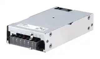
Illustrative purposes only

PJA300F-48
AC/DC Enclosed Power Supply (PSU), ITE, 1 Outputs, 302.4 W, 48 V, 6.3 A
⚠️ Reference pricing provided. In case of supply shortages, we will connect you with our trusted procurement partners to ensure your project's continuity.
- Manufacturer: COSEL
- Product type: AC / DC Enclosed Power Supplies
- SVHC: Lead (04-Feb-2026)
- Product Range: PJA Series
- No. of Outputs: 1Outputs
- Output Power Max: 302.4W
- Current, Output 4: -
- Input Voltage VAC: 85V AC to 264V AC
- Power Supply Output Type: Fixed
- Output Current - Output 1: 6.3A
- Output Current - Output 2: -
- Output Current - Output 3: -
- Output Voltage - Output 1: 48V
- Output Voltage - Output 2: -
- Output Voltage - Output 3: -
- Output Voltage - Output 4: -
- Power Supply Applications: ITE
| Delivery and price | |
|---|---|
| Units per pack | 10 |
| Price | 74.06 € |
| Current stock | 10+ |
| Lead time | 30 days |
Datasheet

**AC-DC Power Supplies Enclosed Type** El : a en eS ~~TD~~ L ETALmye OIK,). Power World wide Cost Safety EMI Inrush OCP OVP Factor Effective Approvals current Correction limiting

## **PJA-series**

## **Feature**

Low Profile  (PJA100F, 150F, 300F : 1U size) (PJA600F, 1000F, 1500F : 2U size)

Wide temperature range (-20C to +70C, Derating is required) Harmonic attenuator (Complies with IEC61000-3-2 class A) Universal input (AC85 - 264V, Derating is required) Low power consumption at no load Complies with SEMI F-47 (PJA1000F, 1500F can meet at 200V input range only) Many optional functions

## **Safety agency approvals**

UL62368-1, C-UL (CSA62368-1), EN62368-1 UL508 (PJA100F, 150F) Complies with DEN-AN

**5-year warranty** (See Instruction Manual)

## **CE marking**

Low Voltage Directive RoHS Directive

## **UKCA marking**

Electrical Equipment Safety Regulations RoHS Regulations

## **EMI**

Complies with FCC-B, CISPR22-B, EN55011-B,  EN55022-B, VCCI-B

(PJA1500F: Class A. In conducted noise, it can meet class B by additional EMI/EMC filter.)

**EMS Compliance** : EN61204-3, EN61000-6-2

EN61000-4-2 EN61000-4-3 EN61000-4-4 EN61000-4-5 EN61000-4-6 EN61000-4-8 EN61000-4-11

**PJA-1**

www.cosel.co.jp/en/

September 19, 2023

## **AC-DC Power Supplies Enclosed Type Ordering information - - PJ A 100 F** O O **PJA100F** 1 2 3 4 5 6

**==> picture [2 x 3] intentionally omitted <==**

**----- Start of picture text -----**<br>
R<br>**----- End of picture text -----**<br>


1Series name **Example recommended EMI/EMC filter NAC-04-472** 2Single output 3Output wattage 4Universal input 5Output voltage eS}€ 6Optional[*][6] C : with Coating R : Remote on/off (Required external High voltage pulse noise type : NAP seriesLow leakage current type : NAM series power source) *A higher current rating EMI/EMC filter J : EP (Tyco Electronics) may be recommended in view of the connector type other devices that could be connected J1 : VH (J.S.T.) in parallel with the power supply. connector type T : Vertical terminal block N2: with DIN rail

**==> picture [316 x 5] intentionally omitted <==**

**----- Start of picture text -----**<br>
a<br>**----- End of picture text -----**<br>


See 6.1 in Instruction Manual.

*Make sure necessary tests will be carried out on your end equipment with the power supply installed in accordance with any required EMC/EMI regulations.

## **SPECIFICATIONS**

||**MODEL**<br>~~(OC~~|**MODEL**<br>~~(OC~~|**PJA100F-12**<br>~~(OC~~|**PJA100F-15**<br>~~(OC~~|**PJA100F-24**<br>~~(OC~~|**PJA100F-36**<br>~~(OC~~|**PJA100F-48**|
|---|---|---|---|---|---|---|---|
|**INPUT**|**VOLTAGE[V]**<br>~~PO~~||AC85 - 264 1f (Output deratingis required at AC85V - 115V. Refer to “Derating” and instruction manual 1.1,3)|||||
||**CURRENT[A]**<br>~~oe~~|**ACIN 100V**<br>~~|~~|1.2typ (Io=90%)|||||
|||**ACIN 115V**<br>~~|~~|1.1typ (Io=100%)|||||
|||**ACIN 230V**<br>~~|~~<br>~~[|~~|0.6typ (Io=100%)|||||
||**FREQUENCY[Hz]**<br>~~PO~~<br>~~oo~~~~**GQ**~~||50 / 60(47 - 63)<br>~~**GQ**~~|||||
||**EFFICIENCY[%]**<br>~~oo~~|**ACIN 100V**<br>~~**GQ**~~|82typ (Io=90%)<br>~~**GQ**~~|83typ (Io=90%)<br>~~**GQ**~~|85typ (Io=90%)<br>~~**GQ**~~|86typ (Io=90%)<br>~~**GQ**~~|86typ (Io=90%)|
|||**ACIN 115V**<br>~~**GQ**~~|82typ (Io=100%)<br>~~**GQ**~~|83typ (Io=100%)<br>~~**GQ**~~|85typ (Io=100%)<br>~~**GQ**~~|86typ (Io=100%)<br>~~**GQ**~~|86typ (Io=100%)|
|||**ACIN 230V**<br>~~**GQ**~~|85typ (Io=100%)<br>~~**GQ**~~|86typ (Io=100%)<br>~~**GQ**~~|88typ (Io=100%)<br>~~**GQ**~~|89typ (Io=100%)<br>~~**GQ**~~|89typ (Io=100%)|
||**POWER FACTOR**<br>~~oo~~<br>~~a~~|**ACIN 100V**<br>~~**GQ**~~<br>~~a~~|0.98typ (Io=90%)<br>~~**GQ**~~|||||
|||**ACIN 115V**<br>~~a~~<br>~~|~~|0.98typ (Io=100%)|||||
|||**ACIN 230V**<br>~~a~~<br>~~|~~<br>~~|~~|0.90typ (Io=100%) *Power factor correction is stopped at AC250V or more.|||||
||**INRUSH CURRENT[A]**<br>~~PF~~|**ACIN 100V**<br>~~PF~~|16typ (Io=90%)Ta=25Cat cold start|||||
|||**ACIN 115V**<br>~~PF~~<br>~~[|~~|16typ (Io=100%)Ta=25Cat cold start|||||
|||**ACIN 230V**<br>~~PF~~<br>~~[|~~|32typ (Io=100%)Ta=25Cat cold start|||||
||**LEAKAGE CURRENT[mA]**<br>~~fr~~||0.75max(ACIN 240V,60Hz,Io=100%,Accordingto IEC62368-1 and DEN-AN)|||||
|**OUTPUT**<br>~~oo~~|**VOLTAGE[V]**<br>~~(n(n~~||12<br>~~(n(n~~|15<br>~~(n(n~~|24<br>~~(n(n~~|36<br>~~(n(n~~|48|
||**CURRENT[A]**<br>~~—~~|**ACIN 85-115V**<br>~~—~~|Output deratingis required at ACIN 115V or less(Refer to “Derating”)|||||
|||**ACIN 115V-264V** <br>~~—~~<br>~~a~~|8.4<br>~~(|~~|6.7<br>~~(|~~|4.3<br>~~(|~~|2.8<br>~~(|~~|2.1|
||**WATTAGE[W]**<br>~~PES~~<br>~~Rs~~|**ACIN 85-115V**<br>~~PES~~|Output deratingis required at ACIN 115V or less(Refer to “Derating”)|||||
|||**ACIN 115V-264V** <br>~~PES~~<br>~~a~~<br>~~s~~|100.8<br>~~GQ~~<br>~~QO~~|100.5<br>~~GQ~~<br>~~QO~~|103.2<br>~~GQ~~<br>~~QO~~|100.8<br>~~GQ~~|100.8|
||**LINE REGULATION[mV]**<br>*3 <br>~~Rs~~<br>~~————————~~||48max<br>~~QO~~<br>~~———————~~|60max<br>~~QO~~<br>~~———————~~|96max<br>~~QO~~<br>~~———————~~|144max|192max|
||**LOAD REGULATION**<br>**[mV]**<br>*3<br>~~Rs~~<br>~~————————~~|**Io=30 to 100%** <br>~~s~~<br>~~———————~~|100max<br>~~QO~~<br>~~———————~~|120max<br>~~QO~~<br>~~———————~~|150max<br>~~QO~~<br>~~———————~~|150max|300max|
|||**Io=0 to 30%** <br>~~———————~~<br>~~[|~~|Burst operation(Please contact us about detail)<br>~~———————~~|||||
||**RIPPLE[mVp-p]**<br>*1<br>Io: load factor<br>~~————————~~<br>~~oe~~<br>~~oo~~|**0 to +40**C <br>~~———————~~<br>~~Re~~|120max<br>~~———————~~<br>~~as~~|120max<br>~~———————~~<br>~~GG~~|120max<br>~~———————~~<br>~~GG~~|150max<br>~~GG~~|150max|
|||**-10 to 0**C <br>~~Re~~<br>~~a~~<br>|160max<br>~~as~~<br>~~es~~<br>|160max<br>~~GG~~<br>|160max<br>~~GG~~<br>|200max<br>~~GG~~<br>|400max|
|||**Io=0 to 30%** <br>~~Re~~<br>~~a~~<br>|500max<br>~~as~~<br>~~es~~<br>|500max<br>~~GG~~<br>|500max<br>~~GG~~<br>|500max<br>~~GG~~<br>|500max|
||**RIPPLE NOISE[mVp-p]**<br>*1<br>Io: load factor<br>~~oo~~<br>~~—————————————~~|**0 to +40**C <br>~~a~~<br>|150max<br>~~es~~<br>|150max<br>|150max<br>|200max<br>|200max|
|||**-10 to 0**C <br>~~a~~<br>~~a~~|180max<br>~~es~~<br>~~GQ~~|180max<br>~~GQ~~|180max<br>~~GQ~~|240max<br>~~GQ~~|500max|
|||**Io=0 to 30%** <br>~~a~~<br><br>~~GQ~~<br>~~—————————————~~|600max<br>~~es~~<br><br>~~GQ~~<br>~~—————————————~~|600max<br><br>~~GQ~~<br>~~—————————————~~|600max<br><br>~~GQ~~<br>~~—————————————~~|600max<br><br>~~GQ~~<br>~~—————————————~~|600max|
||**TEMPERATURE REGULATION[mV]**<br>~~oo~~<br>~~—————————————~~<br>~~Po~~|**0 to +40**C <br>~~a~~<br><br>~~—————————————~~<br>~~Re~~|120max<br>~~es~~<br><br>~~—————————————~~<br>~~GQ~~|150max<br><br>~~—————————————~~<br>~~GQ~~|240max<br><br>~~—————————————~~<br>~~GQ~~|360max<br><br>~~—————————————~~<br>~~GQ~~|480max|
|||**-10 to +40**C <br>~~—————————————~~<br>~~Re~~<br>~~Po~~|180max<br>~~—————————————~~<br>~~GQ~~<br>~~QD~~|180max<br>~~—————————————~~<br>~~GQ~~<br>~~ff~~|290max<br>~~—————————————~~<br>~~GQ~~<br>~~ff~~|440max<br>~~—————————————~~<br>~~GQ~~|600max|
||**DRIFT[mV]**<br>*2 <br>~~—————————————~~<br>~~Re~~<br>~~Rs~~<br>~~Po~~||48max<br>~~—————————————~~<br>~~GQ~~<br>~~Rs~~<br>~~QD~~|60max<br>~~—————————————~~<br>~~GQ~~<br>~~Rs~~<br>~~ff~~|96max<br>~~—————————————~~<br>~~GQ~~<br>~~Rs~~<br>~~ff~~|144max<br>~~—————————————~~<br>~~GQ~~<br>~~Rs~~|192max|
||**START-UP TIME[ms]**<br>~~Po~~||500typ (ACIN 115V,Io=100%)Ta=25C<br>~~QDff~~|||||
||**HOLD-UP TIME[ms]**<br>~~PO~~<br>~~ns~~||20typ (ACIN 115V,Io=100%)<br>~~QO~~|||||
||**OUTPUT VOLTAGE ADJUSTMENT RANGE[V]** <br>~~ns~~||10.80 to 13.20<br>~~QO~~|13.50 to 16.50<br>~~QO~~|21.60 to 26.40<br>~~QO~~|32.40 to 39.60|43.20 to 52.80|
||**OUTPUT VOLTAGE SETTING[V]**<br>~~ns~~<br>~~GQ~~||12.00 to 12.48<br>~~QO~~<br>~~GQ~~|15.00 to 15.60<br>~~QO~~<br>~~GQ~~|24.00 to 24.96<br>~~QO~~<br>~~GQ~~|36.00 to 37.44<br>~~GQ~~|48.00 to 49.92|
|**PROTECTION**<br>**CIRCUIT AND**<br>**OTHERS**|**OVERCURRENT PROTECTION**<br>~~PO~~<br>~~Rs~~||Works over 105% of ratingand recovers automatically<br>~~(Df~~|||||
||**OVERVOLTAGE PROTECTION[V]**<br>~~Rs~~||13.80 to 16.80<br>~~(Df~~|17.25 to 21.00<br>~~(Df~~|27.60 to 33.60|41.40 to 50.40|54.00 to 67.20|
||**OPERATING INDICATION**<br>~~Rs~~<br>~~Po~~||LED(Green)<br>~~(Df~~|||||
||**REMOTE SENSING**<br>~~Po~~||Notprovided|||||
||**REMOTE ON/OFF**<br>~~fr~~||Optional(Required externalpower source. Option -R)|||||
|**ISOLATION**|**INPUT-OUTPUT  RC**<br>*8 <br>~~ee~~||AC3,000V 1minute,Cutoff current = 10mA,DC500V 50MWmin(At room temperature)|||||
||**INPUT-FG**<br>~~PO~~||AC2,000V 1minute,Cutoff current = 10mA,DC500V 50MWmin(At room temperature)|||||
||**OUTPUT  RC-FG**<br>*8 <br>~~Poe~~||AC500V 1minute,Cutoff current = 100mA,DC500V 50MWmin(At room temperature)|||||
||**OUTPUT-RC**<br>*8 <br>~~Po~~||AC500V 1minute,Cutoff current = 100mA,DC500V 50MWmin(At room temperature)|||||
|**ENVIRONMENT**<br>~~[~~|**OPERATING TEMP.,HUMID.AND ALTITUDE** *4 <br>~~Po~~||-20 to +70C (Refer to “Derating”),20 - 90%RH(Non condensing),3,000m(10,000 feet)max|||||
||**STORAGE TEMP.,HUMID.AND ALTITUDE**<br>~~Po~~||-20 to +75C,20 - 90%RH(Non condensing),9,000m(30,000 feet)max|||||
||**VIBRATION**<br>~~Po~~<br>~~[~~||10 - 55Hz,19.6m/s2 (2G),3minutesperiod,60minutes each alongX,Y and Z axes|||||
||**IMPACT**<br>~~[—sY~~||196.1m/s2 (20G),11ms,once each X,Y and Z axes|||||
|**SAFETY AND**<br>**NOISE**<br>**REGULATIONS**<br>~~[~~|**AGENCY APPROVALS**<br>~~[~~<br>~~PO~~||UL62368-1,C-UL(CSA62368-1),EN62368-1,UL508(Except option -J,-J1)Complies with DEN-AN|||||
||**CONDUCTED NOISE**<br>~~PO~~||Complies with FCC-B,VCCI-B,CISPR22-B,EN55011-B,EN55022-B|||||
||**HARMONIC ATTENUATOR** *7<br>~~Po~~||Complies with IEC61000-3-2 class A|||||


**PJA-2**

www.cosel.co.jp/en/

September 19, 2023

## **PJA100F**

## **SPECIFICATIONS**

- **CASE SIZE/WEIGHT** 41X97X109mm [1.61X3.82X4.29 inches] (Excluding terminal block and screw) (WXHXD) / 500g max

- **OTHERS COOLING METHOD** Convection

- **WARRANTY WARRANTY** *5 5 years (subject to the operating conditions) *1  This is the result of measurement of the testing board with hour warm-up at 25C. from input, output, and FG. capacitors of 22mF and 0.1mF placed at 150 mm from the *3  Consult us about dynamic load and input response. Measure the output * Do not use the power supply in overcurrent conditions or in unspecified output terminals by a 20 MHz oscilloscope or a ripple-noise meter voltage by using the average mode of the tester to deal with the burst input voltage ranges. Otherwise the internal components may be equivalent to Keisoku-Giken RM103. operation at 30% load or less. damaged.

See 1.6 of Instruction Manual for more details.

- *4  Output power derating is required. Refer to “Derating”.

      - Parallel operation is not possible with this mode.

   - When the load factor is 0 - 30%, the switching power loss is *5  See 4 in Instruction Manual for more details. * Sound noise may be heard from the power supply when used for reduced by burst operation, which will cause ripple and ripple *6 Consult us about safety agency approvals for the models with optional functions. pulse load. noise to go beyond the specifications. *7  Consult us about other classes.

- *2  Drift is the change in DC output for an eight hour period after a half*8  The RC terminal is added to option –R models. The RC terminal is isolated

## **Features**

## **- Compact design (Depth: 109mm 4.29inches)**

- **High efficiency (88%typ PJA100F-24, AC230Vin, 100% load)**

- **Low power consumption (1.5W typ AC240Vin, no load at standard model)**

- **UL508 approved (Except option -J, -J1), and complies with SEMI F47 (see instruction manual 1.1)**

- **Various connection interface options (vertical terminal [-T], AMP connector [-J], [-J1])**

## **Block diagram**

**==> picture [390 x 164] intentionally omitted <==**

**----- Start of picture text -----**<br>
FUSE<br>250V 3.15A NOISE INRUSH<br>AC IN 85 - 264V FILTER RECTIFIER CURRENT<br>LIMIT<br>FG<br>RC(-R)<br>BOOSTER CURRENT EXTERNAL<br>INDUCTOR SENSING SOURCE<br>CONTROL<br>CURRENT RECTIFIER<br>SENSING AND<br>FILTER<br>OVER VOLTAGE<br>INVERTER PROTECTION<br>RECTIFIER<br>INVERTER AND DC OUT<br>CONTROL FILTER<br>**----- End of picture text -----**<br>


## **External view**

The external size of –R option, –J option, –J1 option, –N2 option and –T option models is different from the standard model. See “6. Options and Others” in Instruction Manual for more details.

**==> picture [475 x 254] intentionally omitted <==**

**----- Start of picture text -----**<br>
2-M3<br>Name plate Mounting hole<br>(Bottom side)<br>M3.5<br>AC(L)<br>Terminal cover<br>AC(N) Point A<br>FG(   )<br>Output terminal(–)<br>Output terminal(+)<br>Output voltage<br>adjustable potentiometer<br>LED<br>2<br>CN4 1<br>Connector for<br>Remote ON/OFF (option) 19.5 76±0.5<br>[0.77] [2.99]<br>12.5max 109<br>11.2±1.5 (potentiometer) [0.49] [4.29]<br>[0.44]<br>14±1.5 4 101<br>[0.55] [0.16] [3.98]<br>¶ Tolerance : ±1 [±0.04] 15.3±1.5 (LED)<br>[0.6]<br>¶ Weight : 500g max<br>¶ PCB Material/thickness : FR-4 / 1.6mm [0.06inches]<br>¶ Chassis material : Aluminum<br>¶ Cover material : Galvanizing steel<br>¶ Dimensions in mm, [  ]=inches<br>¶ Mounting torque : 0.49N-m max<br>¶ Screw tightening torque : M3.5 1.0N-m max 33.5 66.5±0.5 3-M3<br>¶ Connect the input FG to safety earth ground. [1.32] [2.62] Mounting hole<br>8.2 [0.32] 9.5 [0.37] 97 [3.82]<br>±1.5 6.2 [0.24] 51 [2.01]<br>22±1.5 [0.87] 32.8 [1.29]<br>±1.5<br>14.6 [0.57]<br>3.5 [0.14]<br>28.5 [1.12] 21 [0.83] 3.5 [0.14] 21 [0.83] 1218±0.5 [0.71][0.47] 41 [1.61]<br>**----- End of picture text -----**<br>


**==> picture [84 x 10] intentionally omitted <==**

**----- Start of picture text -----**<br>
September 19, 2023<br>**----- End of picture text -----**<br>


**PJA-3**

www.cosel.co.jp/en/

**AC-DC Power Supplies Enclosed Type PJA150F** ~~|~~

**Ordering information**

**PJ A 150 F** O O 1 2 3 4 5 6

**==> picture [2 x 3] intentionally omitted <==**

**----- Start of picture text -----**<br>
R<br>**----- End of picture text -----**<br>


1Series name **Example recommended EMI/EMC filter NAC-04-472** 2Single output 3Output wattage — 4Universal input :a) o520 5Output voltage tI a rs 6Optional[*][6] C : with Coating R : Remote on/off (Required external High voltage pulse noise type : NAP seriesLow leakage current type : NAM series power source) fs], 4 lat *A higher current rating EMI/EMC filter J : EP (Tyco Electronics) may be recommended in view of the connector type i” tgs other devices that could be connected J1 : VH (J.S.T.) in parallel with the power supply. connector type : T : Vertical terminal block la" N2: with DIN rail See 6.1 in Instruction Manual.

*Make sure necessary tests will be carried out on your end equipment with the power supply installed in accordance with any required EMC/EMI regulations.

## **SPECIFICATIONS**

* Please consider "PBA150F-5-N" about 5V output with case cover.

**==> picture [484 x 510] intentionally omitted <==**

**----- Start of picture text -----**<br>
|||||||||||||||
|---|---|---|---|---|---|---|---|---|---|---|---|---|---|
|a|MODEL|PJA150F-12|PJA150F-15|PJA150F-24|PJA150F-36|PJA150F-48|
|Po|VOLTAGE[V]|AC85 - 264 1f|(Output derating is required at AC85V - 115V. Refer to “Derating” and instruction manual 1.1, 3)|
||||ACIN 100V|1.7typ|(Io=90%)|
|CURRENT[A]||||ACIN 115V|1.6typ|(Io=100%)|
|ACIN 230V|0.8typ|(Io=100%)|
|||
|FREQUENCY[Hz]|50 / 60 (47 - 63)|
|||||
|ACIN 100V|84typ|(Io=90%)|84typ|(Io=90%)|87typ|(Io=90%)|87typ|(Io=90%)|87typ|(Io=90%)|
|a|es|
|EFFICIENCY[%]|a|ACIN 115V|a|84typ|(Io=100%)|84typ|(Io=100%)|87typ|(Io=100%)|87typ|(Io=100%)|87typ|(Io=100%)|
|INPUT|a|ACIN 230V|a|87typ|(Io=100%)|87typ|(Io=100%)|90typ|(Io=100%)|90typ|(Io=100%)|90typ|(Io=100%)|
||||ACIN 100V|0.98typ|(Io=90%)|
|POWER FACTOR||||ACIN 115V|0.98typ|(Io=100%)|
|ACIN 230V|0.93typ|(Io=100%)|* Power factor correction is stopped at AC250V or more.|
|||[|]|
||||ACIN 100V|16typ|(Io=90%) Ta=25C at cold start|
|INRUSH CURRENT[A]||||ACIN 115V|16typ|(Io=100%) Ta=25C at cold start|
|ACIN 230V|32typ|(Io=100%) Ta=25C at cold start|
|LEAKAGE CURRENT[mA]|0.75max (ACIN 240V, 60Hz, Io=100%, According to IEC62368-1 and DEN-AN)|
|||[C—“‘CSCs*zCT]||||
|a|VOLTAGE[V]|12|15|24|36|48|
|ACIN 85-115V|Output derating is required at ACIN 115V or less (Refer to “Derating”)|
|CURRENT[A]|
|Poa|ACIN 115V-264V|||12.5|10|6.4|4.2|3.2|
|ACIN 85-115V|Output derating is required at ACIN 115V or less (Refer to “Derating”)|
|WATTAGE[W]|
|PEa|ACIN 115V-264V|150.0|150.0|153.6|151.2|153.6|
|GG|LINE REGULATION[mV]|*3|48max|60max|96max|144max|192max|
|LOAD REGULATION|Io=30 to 100%|100max|120max|150max|150max|300max|
|—|[mV]|——————|*3||||Io=0 to 30%|Burst operation (Please contact us about detail)|
|RIPPLE[mVp-p]|a|0 to +40|C|a|120max|120max|120max|150max|150max|
|*1|a|-10 to 0|C|160max|160max|160max|200max|400max|
|OUTPUT|Io: load factor|a|Io=0 to 30%|as|500max|500max|500max|500max|500max|
|RIPPLE NOISE[mVp-p]|a|0 to +40|C|150max|es|150max|150max|200max|200max|
|*1|-10 to 0|C|180max|180max|180max|240max|500max|
|Io: load factor|a|Io=0 to 30%|600max|es|600max|600max|600max|600max|
|a as|
|0 to +40|C|120max|150max|240max|360max|480max|
|TEMPERATURE REGULATION[mV]|
|-10 to +40|C|180max|180max|290max|440max|600max|
|esGe|DRIFT[mV]|a|*2|48max|esee|GG|60max|ee|96max|ee|144max|ee|192max|
|START-UP TIME[ms]|500typ|(ACIN 115V, Io=100%) Ta=25C|
|||[SY]|
|HOLD-UP TIME[ms]|20typ|(ACIN 115V, Io=100%)|
|||
|GG|OUTPUT VOLTAGE ADJUSTMENT RANGE[V]|10.80 to 13.20|13.50 to 16.50|21.60 to 26.40|32.40 to 39.60|43.20 to 52.80|
|OUTPUT VOLTAGE SETTING[V]|12.00 to 12.48|15.00 to 15.60|24.00 to 24.96|36.00 to 37.44|48.00 to 49.92|
|a|G|
|Po|OVERCURRENT PROTECTION|Works over 105% of rating and recovers automatically|
|PROTECTION|a|OVERVOLTAGE PROTECTION[V]|GP|13.80 to 16.80|17.25 to 21.00|27.60 to 33.60|41.40 to 50.40|54.00 to 67.20|
|CIRCUIT AND|Po|OPERATING INDICATION|LED (Green)|
|OTHERS|Po|REMOTE SENSING|Not provided|
|REMOTE ON/OFF|Optional (Required external power source. Option -R)|
|LT|
|Po|INPUT-OUTPUT  RC|*8|AC3,000V 1minute, Cutoff current = 10mA, DC500V 50MW min (At room temperature)|
|ISOLATION|po|INPUT-FG|AC2,000V 1minute, Cutoff current = 10mA, DC500V 50MW min (At room temperature)|
|Poe|OUTPUT  RC-FG|*8|AC500V 1minute, Cutoff current = 100mA, DC500V 50MW min (At room temperature)|
|||C—“‘Csi‘CSsCSCsz|Po|OUTPUT-RCOPERATING TEMP.,HUMID.AND ALTITUDE|[*]|*|[4]|8|AC500V 1minute-20 to +70C|(Refer to “Deratin, Cutoff current = 100mAg”), 20 - 90%RH , DC500V 50M(Non condensinW min g),(At room tem 3,000m (10p,erature000 feet)|) max|
|ENVIRONMENT|Po|STORAGE TEMP.,HUMID.AND ALTITUDE|-20 to +75C, 20 - 90%RH (Non condensing), 9,000m (30,000 feet) max|
|VIBRATION|10 - 55Hz, 19.6m/s|[2]|(2G), 3minutes period, 60minutes each along X, Y and Z axes|
|||
|[||IMPACT|196.1m/s|[2]|(20G), 11ms, once each X, Y and Z axes|
|SAFETY AND|Po|AGENCY APPROVALS|UL62368-1, C-UL (CSA62368-1), EN62368-1, UL508 (Except option -J, -J1) Complies with DEN-AN|
|NOISE|Po|CONDUCTED NOISE|Complies with FCC-B, VCCI-B, CISPR22-B, EN55011-B, EN55022-B|
|REGULATIONS|HARMONIC ATTENUATOR|[*][7]|Complies with IEC61000-3-2 class A|
|||

**----- End of picture text -----**<br>


**PJA-4**

www.cosel.co.jp/en/

September 19, 2023

## **PJA150F**

## **SPECIFICATIONS**

- **CASE SIZE/WEIGHT** 41X97X129mm [1.61X3.82X5.08 inches] (Excluding terminal block and screw) (WXHXD) / 600g max

- **OTHERS COOLING METHOD** Convection

- **WARRANTY WARRANTY** *5 5 years (subject to the operating conditions) *1  This is the result of measurement of the testing board with capacitors of hour warm-up at 25C. isolated from input, output, and FG. 22mF and 0.1mF placed at 150 mm from the output terminals by a 20 *3  Consult us about dynamic load and input response. Measure the output * Do not use the power supply in overcurrent conditions or in unspecified MHz oscilloscope or a ripple-noise meter equivalent to Keisoku-Giken voltage by using the average mode of the tester to deal with the burst input voltage ranges. Otherwise the internal components may be RM103. operation at 30% load or less. damaged.

   - See 1.6 of Instruction Manual for more details. *4  Output power derating is required. Refer to “Derating”. * Parallel operation is not possible with this mode. When the load factor is 0 - 30%, the switching power loss is reduced by *5  See 4 in Instruction Manual for more details. * Sound noise may be heard from the power supply when used for burst operation, which will cause ripple and ripple noise to go beyond *6 Consult us about safety agency approvals for the models with optional functions. pulse load. the specifications. *7  Consult us about other classes.

- *2  Drift is the change in DC output for an eight hour period after a half*8  The RC terminal is added to option –R models. The RC terminal is

## **Features**

- **Compact design (Depth: 129mm 5.08inches)**

- **High efficiency (90%typ PJA150F-24, AC230Vin, 100% load)**

- **Low power consumption (1.5W typ AC240Vin, no load at standard model)**

- **UL508 approved (Except option -J, -J1), and complies with SEMI F47 (see instruction manual 1.1)**

- **Various connection interface options (vertical terminal [-T], AMP connector [-J], [-J1])**

## **Block diagram**

**==> picture [390 x 164] intentionally omitted <==**

**----- Start of picture text -----**<br>
FUSE<br>250V 4A NOISE INRUSH<br>AC IN 85 - 264V FILTER RECTIFIER CURRENT<br>LIMIT<br>FG<br>RC(-R)<br>BOOSTER CURRENT EXTERNAL<br>INDUCTOR SENSING SOURCE<br>CONTROL<br>CURRENT RECTIFIER<br>SENSING AND<br>FILTER<br>OVER VOLTAGE<br>INVERTER PROTECTION<br>RECTIFIER<br>INVERTER AND DC OUT<br>CONTROL FILTER<br>**----- End of picture text -----**<br>


## **External view**

The external size of –R option, –J option, –J1 option, –N2 option and –T option models is different from the standard model. See “6. Options and Others” in Instruction Manual for more details.

**==> picture [485 x 254] intentionally omitted <==**

**----- Start of picture text -----**<br>
2-M3<br>Name plate<br>Point B Mounting hole<br>M3.5 (Bottom side)<br>AC(L)<br>Terminal cover<br>AC(N) Point A<br>FG(   )<br>Output terminal(–)<br>Output terminal(+)<br>Output voltage<br>adjustable potentiometer<br>LED<br>2<br>1<br>CN4<br>Connector for 19 96±0.5<br>Remote ON/OFF (option) [0.75] [3.78]<br>12.5max 129<br>11.2±1.5 (potentiometer) [0.49] [5.08]<br>[0.44]<br>14±1.5<br>[0.55] 4 121<br>15.3±1.5 (LED) [0.16] [4.76]<br>¶ Tolerance : ±1 [±0.04] [0.6]<br>¶ Weight : 600g max<br>¶ PCB Material/thickness : FR-4 / 1.6mm [0.06inches]<br>¶ Chassis material : Aluminum<br>¶ Cover material : Galvanizing steel<br>¶ Dimensions in mm, [  ]=inches<br>¶ Mounting torque : 0.49N-m max<br>¶ Screw tightening torque : M3.5 1.0N-m max 48 70±0.5 3-M3<br>¶ Connect the input FG to safety earth ground. [1.89] [2.76] Mounting hole<br>8.2 [0.32] 95. [0.37] 97 [3.82]<br>±1.5 6.2 [0.24] B 945. [1.95]<br>8<br>±1.5 [0.87] 2.3 [1.29]<br>22<br>±1.5<br>614. [0.57]<br>3.5 [0.14]<br>825. [1.12] 21 [0.83] 3.5 [0.14] 21 [0.83] 1218±0.5 [0.71][0.47] 41 [1.61]<br>**----- End of picture text -----**<br>


**==> picture [84 x 10] intentionally omitted <==**

**----- Start of picture text -----**<br>
September 19, 2023<br>**----- End of picture text -----**<br>


**PJA-5**

www.cosel.co.jp/en/

**==> picture [260 x 84] intentionally omitted <==**

**----- Start of picture text -----**<br>
AC-DC Power Supplies Enclosed Type<br>PJA300F<br>|<br>R<br>AL: (D)C E UK<br>**----- End of picture text -----**<br>


## **Ordering information**

**==> picture [323 x 143] intentionally omitted <==**

**----- Start of picture text -----**<br>
- -<br> PJ  A  300  F  O O<br>1  2  3  4  5  6<br>1Series name<br>Example recommended EMI/EMC filter<br>NAC-06-472 2Single output<br>3Output wattage<br>——<br>4Universal input<br>5Output voltage<br>6Optional   [*][6]<br>C : with Coating<br> G: Low leakage current<br> V : External potentiometer for<br>High voltage pulse noise type : NAP seriesLow leakage current type : NAM series output voltage adjustment<br>R : Remote on/off<br>*A higher current rating EMI/EMC filter may be recommended in view of the  (Required external power source)<br>other devices that could be connected  F4: Low speed fan<br>in parallel with the power supply.<br>é See 6.1 in Instruction Manual.<br>**----- End of picture text -----**<br>


*Make sure necessary tests will be carried out on your end equipment with the power supply installed in accordance with any required EMC/EMI regulations.

## **SPECIFICATIONS**

||**MODEL**<br>~~PT~~|**MODEL**<br>~~PT~~|**PJA300F-5**<br>~~PT~~|**PJA300F-12**<br>~~PT~~|**PJA300F-15**<br>~~PT~~|**PJA300F-24**<br>~~PT~~|**PJA300F-36**<br>~~PT~~|**PJA300F-48**|
|---|---|---|---|---|---|---|---|---|
|**INPUT**|**VOLTAGE[V]**<br>~~Po~~||AC85 - 264 1f (Output deratingis required at AC85V - 100V. Refer to “Derating” and instruction manual 1.1,3)<br>||||||
||**CURRENT[A]**<br>|**ACIN 100V**<br>~~a~~|3.5typ (Io=100%)<br>~~a~~|3.9typ (Io=100%)|||||
|||**ACIN 115V**<br>~~a~~|3.0typ (Io=100%)<br>~~a~~|3.3typ (Io=100%)|||||
|||**ACIN 230V**<br>~~a~~|1.5typ (Io=100%)<br>~~a~~|1.7typ (Io=100%)|||||
||**FREQUENCY[Hz]**<br>~~Po~~||50 / 60(47 - 63)||||||
||**EFFICIENCY[%]**<br>~~Po~~<br>~~|~~|**ACIN 100V**<br>~~Po~~<br>~~a ~~|73typ (Io=100%)<br> ~~a~~|79typ (Io=100%)<br>~~a ~~|81typ (Io=100%)<br> ~~ee~~|82typ (Io=100%)<br>~~ee~~|83typ (Io=100%)<br>~~ee~~|82typ (Io=100%)|
|||**ACIN 115V**<br>~~a ~~|74typ (Io=100%)<br> ~~a ~~|80typ (Io=100%)<br> ~~Qe~~|82typ (Io=100%)<br>~~Qe~~|83typ (Io=100%)<br>~~Qe~~|83typ (Io=100%)<br>~~Qe~~|83typ (Io=100%)|
|||**ACIN 230V**<br>~~|~~|77typ (Io=100%)|82typ (Io=100%)|84typ (Io=100%)|86typ (Io=100%)|87typ (Io=100%)|86typ (Io=100%)|
||**POWER FACTOR**<br>~~|~~<br>~~oe~~<br>~~|~~|**ACIN 100V**<br>~~|~~<br>~~oe~~|0.99typ (Io=100%)||||||
|||**ACIN 115V**<br>~~|~~<br>~~oe~~<br>~~|~~|0.98typ (Io=100%)||||||
|||**ACIN 230V**<br>~~oe~~<br>~~||~~|0.95typ (Io=100%)||||||
||**INRUSH CURRENT[A]**<br>~~|~~<br>~~|~~|**ACIN 100V**<br>~~|~~<br>~~|_|~~|20typ (Io=100%)Ta=25Cat cold start||||||
|||**ACIN 115V**<br>~~|~~<br>~~|~~|20typ (Io=100%)Ta=25Cat cold start||||||
|||**ACIN 230V**<br>~~|~~<br>~~|~~|40typ (Io=100%)Ta=25Cat cold start||||||
||**LEAKAGE CURRENT[mA]**<br>~~|~~<br>~~Po~~||0.75max(ACIN 240V,60Hz,Io=100%,Accordingto IEC62368-1 and DEN-AN)||||||
|**OUTPUT**<br>~~Pe~~|**VOLTAGE[V]**<br>~~a~~<br>~~ce~~||5<br>~~ee~~|12<br>~~ee~~|15<br>~~ee~~|24<br>~~ee~~|36<br>~~ee~~|48<br>~~ee~~|
||**CURRENT[A]**<br>~~ce~~<br>~~ee~~|**ACIN 85-100V**<br>~~ce~~|Output deratingis required at ACIN 100V or less(Refer to “Derating”)<br>~~ee~~<br>~~eeee~~<br>~~ee~~<br>~~ee~~||||||
|||**ACIN 100V-264V** <br>~~ce~~<br>~~ee~~|50<br>~~ee~~<br>~~es~~|25<br>~~ee~~<br>~~ee~~|20<br>~~ee~~<br>~~ee~~|12.5<br>~~ee~~<br>~~ee~~|8.4<br>~~ee~~|6.3<br>~~ee~~|
||**WATTAGE[W]**<br>~~ce~~<br>~~ee~~|**ACIN 85-100V**<br>~~ce ~~<br>~~ee~~|Output deratingis required at ACIN 100V or less(Refer to “Derating”)<br> ~~ee~~<br>~~ee ee~~<br>~~ee~~<br>~~ee~~<br>~~es~~<br>~~ee~~<br>~~ee~~<br>~~ee~~||||||
|||**ACIN 100V-264V** <br>~~ee~~|250<br>~~es~~|300<br>~~ee~~|300<br>~~ee~~|300<br>~~ee~~|302.4|302.4|
||**LINE REGULATION[mV]**<br>*3 <br>~~ee ee~~<br>~~a ~~||20max<br>~~es~~<br> ~~eG~~|48max<br>~~ee~~<br>~~eG~~|60max<br>~~ee~~<br>~~eG~~|96max<br>~~ee~~<br>~~eG~~|144max<br>~~eG~~|192max|
||**LOAD REGULATION[mV]**<br>*3 <br>~~a ~~||40max<br> ~~GG~~|100max<br>~~GG~~|120max<br>~~GG~~|150max<br>~~GG~~|150max<br>~~GG~~|300max|
||**RIPPLE[mVp-p]**<br>*1<br>~~Pe~~<br>~~_~~|**0 to +50**C|80max|120max|120max|120max|150max|150max|
|||**-10 to 0**C <br>~~a a~~|140max<br>~~a~~|160max|160max<br>~~]_~~|160max<br>~~]_~~|160max<br>~~AR~~|400max|
||**RIPPLE NOISE[mVp-p]**<br>*1<br>~~Pe~~<br>~~_~~<br>~~es~~|**0 to +50**C <br>~~a a~~|120max<br>~~a~~|150max|150max<br>~~]_~~|150max<br>~~]_~~|200max<br>~~AR~~|200max|
|||**-10 to 0**C <br>~~a a~~<br>~~es~~|160max<br>~~a~~<br>~~ces~~|180max<br>~~ee ce~~|180max<br>~~]_~~<br>~~ce ee~~|180max<br>~~]_~~<br>~~ee~~|240max<br>~~AR~~|500max|
||**TEMPERATURE REGULATION[mV]**<br>~~Pe~~<br>~~_~~<br>~~es~~|**0 to +50**C <br>~~a a~~<br>~~es~~|50max<br>~~a~~<br>~~ces~~|120max<br>~~ee ce~~|150max<br>~~]_~~<br>~~ce ee~~|240max<br>~~]_ ~~<br>~~ee~~|360max<br> ~~AR~~|480max|
|||**-10 to +50**C <br>~~es~~|75max<br>~~ces~~|180max<br>~~ee ce~~|180max<br>~~ce ee~~|290max<br>~~ee~~|440max|600max|
||**DRIFT[mV]**<br>*2 <br>~~es~~<br>~~a ~~||20max<br>~~ces ~~<br> ~~DG~~|48max<br> ~~ee ce~~<br>~~DG~~|60max<br>~~ce ee~~<br>~~DG~~|96max<br>~~ee~~<br>~~DG~~|144max<br>~~DG~~|192max|
||**START-UP TIME[ms]**<br>~~po~~||300typ (ACIN 100V,Io=100%)||||||
||**HOLD-UP TIME[ms]**<br>~~po~~<br>~~a~~||20typ (ACIN 100V,Io=100%)<br>~~ee~~<br>~~OG~~||||||
||**OUTPUT VOLTAGE ADJUSTMENT RANGE[V]** <br>~~a~~||4.50 to 5.50<br>~~ee~~|10.80 to 13.20|13.50 to 16.50<br>~~OG~~|21.60 to 26.40<br>~~OG~~|32.40 to 39.60|43.20 to 52.80|
||**OUTPUT VOLTAGE SETTING[V]**<br>~~a~~||5.00 to 5.15<br>~~ee~~|12.00 to 12.48|15.00 to 15.60<br>~~OG~~|24.00 to 24.96<br>~~OG~~|36.00 to 37.44|48.00 to 49.92|
|**PROTECTION**<br>**CIRCUIT AND**<br>**OTHERS**|**OVERCURRENT PROTECTION**<br>~~Po~~<br>~~a~~||Works over 105% of ratingand recovers automatically<br>~~Pe~~<br>~~eG~~||||||
||**OVERVOLTAGE PROTECTION[V]**<br>~~a~~||5.75 to 7.00<br>~~Pe~~|13.80 to 16.80<br>~~eG~~|17.25 to 21.00<br>~~eG~~|27.60 to 33.60|41.40 to 50.40|55.20 to 67.20|
||**OPERATING INDICATION**<br>~~a~~<br>~~po~~||LED(Green)<br>~~Pe~~<br>~~eG~~||||||
||**REMOTE SENSING**<br>~~po~~||Notprovided||||||
||**REMOTE ON/OFF**<br>~~Po~~||Optional(Required externalpower source. Option -R)||||||
|**ISOLATION**|**INPUT-OUTPUT  RC**<br>*9 <br>~~Po~~||AC3,000V 1minute,Cutoff current = 10mA,DC500V 50MWmin(At room temperature)||||||
||**INPUT-FG**<br>~~po~~||AC2,000V 1minute,Cutoff current = 10mA,DC500V 50MWmin(At room temperature)||||||
||**OUTPUT  RC-FG**<br>*9 <br>~~po~~||AC500V 1minute,Cutoff current = 100mA,DC500V 50MWmin(At room temperature)||||||
||**OUTPUT-RC**<br>*9 <br>~~po~~||AC500V 1minute,Cutoff current = 100mA,DC500V 50MWmin(At room temperature)||||||
|**ENVIRONMENT**|**OPERATING TEMP.,HUMID.AND ALTITUDE** *4 <br>~~Po~~||-20 to +70C (Refer to “Derating”),20 - 90%RH(Non condensing),3,000m(10,000 feet)max||||||
||**STORAGE TEMP.,HUMID.AND ALTITUDE**<br>~~po~~||-20 to +75C,20 - 90%RH(Non condensing),9,000m(30,000 feet)max||||||
||**VIBRATION**<br>~~po~~||10 - 55Hz,19.6m/s2 (2G),3minutesperiod,60minutes each alongX,Y and Z axes||||||
||**IMPACT**<br>~~Po~~||196.1m/s2 (20G),11ms,once each X,Y and Z axes||||||
|**SAFETY AND**<br>**NOISE**<br>**REGULATIONS**|**AGENCY APPROVALS**<br>~~Po~~||UL62368-1,C-UL(CSA62368-1),EN62368-1 Complies with DEN-AN||||||
||**CONDUCTED NOISE**<br>~~po~~||Complies with FCC-B,VCCI-B,CISPR22-B,EN55011-B,EN55022-B||||||
||**HARMONIC ATTENUATOR** *8<br>~~Po~~||Complies with IEC61000-3-2 class A||||||


**PJA-6**

www.cosel.co.jp/en/

September 19, 2023

## **PJA300F**

## **SPECIFICATIONS**

|**OTHERS**|**CASE SIZE/WEIGHT**|102X41X190mm[4.02X1.61X7.48 inches] (Excludingterminal block and screw) (WXHXD)/ 1.0kgmax|
|---|---|---|
||**COOLING METHOD**<br>*7|Forced cooling (internal fan)|
|**WARRANTY **|**WARRANTY**<br>*5|5years(subject to the operatingconditions)|


- *1  This is the result of measurement of the testing board with capacitors of *3  Consult us about dynamic load and input response. 22mF and 0.1mF placed at 150 mm from the output terminals by a 20 *4  Output power derating is required. Refer to “Derating”. MHz oscilloscope or a ripple-noise meter equivalent to Keisoku-Giken *5  See 4 in Instruction Manual for more details. RM103. *66

      - *66 Consult us about safety agency approvals for the models with optional functions.

      - *7  The fan speed slows down at no load.

   - See 1.6 of Instruction Manual for more details.

- *2  Drift is the change in DC output for an eight hour period after a half-hour *8  Consult us about other classes. warm-up at 25C. *9  The RC terminal is added to option –R models. The RC terminal is

   - isolated from input, output, and FG.

- Do not use the power supply in overcurrent conditions or in unspecified input voltage ranges. Otherwise the internal components may be damaged.

- Parallel operation is not possible with this mode.

- Sound noise may be heard from the power supply when used for pulse load.

## **Features**

## **- Cost-effective**

- **Longer life (see Instruction Manual)**

- **Low profile (meets 1U height = 41 mm or 1.61 inches)**

- **Wide operating temperature range (-20 to +70 Refer to “Derating”)**

- **Slow fan speed at no load**

- **Complies with SEMI F-47**

- **Many optional functions**

## **Block diagram**

**==> picture [384 x 162] intentionally omitted <==**

**----- Start of picture text -----**<br>
FUSE<br>250V 10A NOISE INRUSH<br>AC IN 85 - 264V FILTER RECTIFIER CURRENT<br>LIMIT<br>FG<br>BOOSTER CURRENT CONTROL<br>INDUCTOR SENSING<br>CURRENT RECTIFIER<br>SENSING AND CONTROL OVER VOLTAGE<br>FILTER<br>PROTECTION<br>INVERTER<br>RECTIFIER<br>INVERTER AND DC OUT<br>FILTER<br>CONTROL<br>THERMAL CONTROL FAN<br>PROTECTION<br>**----- End of picture text -----**<br>


## **External view**

The external size of –V option and –R option models is different from the standard model. See “6. Options and Others” in Instruction Manual for more details.

**==> picture [428 x 235] intentionally omitted <==**

**----- Start of picture text -----**<br>
16.8±1.5 (LED)<br>[0.66]<br>12.7±1.5 (potentiometer)<br>[0.5] Name plate 4-M4<br>LED 20max Mounting Hole<br>Output voltage [0.79max] (Bottom side)<br>adjustable potentiometer<br>Output terminal(+)<br>Output terminal(–)<br>FG( )<br>AC(N) Terminal cover<br>AC(L)<br>M4 12.5 150±0.5<br>16.6±1.5 [0.49] [5.91]<br>[0.65] 190 5max<br>[7.48] [0.2max]<br>¶ Tolerance : ±1 [±0.04]<br>¶ Weight : 1.0kg max AIR FLOW<br>¶ PCB Material/thickness : FR-4 / 1.6mm [0.06inches]<br>¶ Chassis material : Aluminum<br>¶ Case material : Galvanizing steel<br>¶ Dimensions in mm, [  ]=inches<br>¶ Mounting torque : 1.2N    m max 19.5 150±0.5<br>¶ Screw tightening torque : 1.6N    m max [0.77] [5.91] 4-M4<br>¶ Connect the input FG to safety earth ground. Mounting Hole<br>1.5 1.5 1.5<br>± [0.23] ± [0.49] ± [0.78]<br>5.75 12.5 19.8<br>6.7 [0.26]<br>V.ADJ<br>+V<br>+V<br>-V-V FG 10 [0.39] 600.5± [2.36] 102 [4.02]<br>()NAC<br>(L)AC<br>8.6 [0.34]<br>9.5<br>1 [0.77]<br>0.5<br>25± [0.98] 41 [1.61]<br>0.5<br>1 [0.41]<br>**----- End of picture text -----**<br>


**PJA-7**

www.cosel.co.jp/en/

September 19, 2023

**AC-DC Power Supplies Enclosed Type PJA600F** ~~eS~~

**Ordering information**

**PJ A 600 F** O O

1 2 3 4 5 6

**==> picture [2 x 3] intentionally omitted <==**

**----- Start of picture text -----**<br>
R<br>**----- End of picture text -----**<br>


**Example recommended EMI/EMC filter NAC-16-472** oe" High voltage pulse noise type : NAP series Low leakage current type : NAM series “ *A higher current rating EMI/EMC filter may be recommended in view of the other devices that could be connected in parallel with the power supply.

1Series name 2Single output 3Output wattage

4Universal input

5Output voltage 6Optional[*][6] C : with Coating G : Low leakage current V : External potentiometer for output voltage adjustment W: Parallel operation, LV alarm and Remote sensing R : Remote on/off (Required external power source) F4 : Low speed fan

**==> picture [83 x 6] intentionally omitted <==**

**----- Start of picture text -----**<br>
See 6.1 in Instruction Manual.<br>**----- End of picture text -----**<br>


*Make sure necessary tests will be carried out on your end equipment with the power supply installed in accordance with any required EMC/EMI regulations.

## **SPECIFICATIONS**

||**MODEL**<br>~~a~~|**MODEL**<br>~~a~~|**PJA600F-5**<br>~~CO~~|**PJA600F-12**<br>~~CO~~|**PJA600F-15**|**PJA600F-24**|**PJA600F-36**|**PJA600F-48**|
|---|---|---|---|---|---|---|---|---|
|**INPUT**<br>~~LT~~|**VOLTAGE[V]**<br>~~Po~~||AC85 - 264 1f (Output deratingis required at AC85V - 100V. Refer to “Derating” and instruction manual 1.1,3)||||||
||**CURRENT[A]**|**ACIN 100V**<br>~~a~~|6.7typ (Io=100%)|7.5typ (Io=100%)|||||
|||**ACIN 115V**<br>~~a~~|5.7typ (Io=100%)|6.5typ (Io=100%)|||||
|||**ACIN 230V**<br>~~a~~|2.8typ (Io=100%)|3.2typ (Io=100%)|||||
||**FREQUENCY[Hz]**<br>~~Po~~||50 / 60(47 - 63)||||||
||**EFFICIENCY[%]**<br>~~Po~~|**ACIN 100V**<br>~~Po~~<br>~~a~~|76typ (Io=100%)|81typ (Io=100%)|82typ (Io=100%)|84typ (Io=100%)|85typ (Io=100%)|85typ (Io=100%)|
|||**ACIN 115V**<br>~~a~~|77typ (Io=100%)|82typ (Io=100%)|82typ (Io=100%)|85typ (Io=100%)|86typ (Io=100%)|85typ (Io=100%)|
|||**ACIN 230V**|79typ (Io=100%)|84typ (Io=100%)|85typ (Io=100%)|88typ (Io=100%)|88typ (Io=100%)|88typ (Io=100%)|
||**POWER FACTOR**<br>~~=~~<br>~~|~~|**ACIN 100V**<br>~~[|~~<br>~~=~~|0.99typ (Io=100%)||||||
|||**ACIN 115V**<br>~~=~~<br>~~|~~|0.98typ (Io=100%)||||||
|||**ACIN 230V**<br>~~=~~<br>~~|~~|0.95typ (Io=100%)||||||
||**INRUSH CURRENT[A]**<br>~~|~~<br>~~ee~~<br>~~|~~<br>~~LT~~|**ACIN 100V**<br>~~|~~<br>~~||~~|20/40typ (Io=100%) (Primaryinrush current /Secondaryinrush current) (More than 3sec to re-start)||||||
|||**ACIN 115V**<br>~~||~~<br>~~|~~|20/40typ (Io=100%) (Primaryinrush current /Secondaryinrush current) (More than 3sec to re-start)||||||
|||**ACIN 230V**<br>~~||~~<br>~~|~~|40/40typ (Io=100%) (Primaryinrush current /Secondaryinrush current) (More than 3sec to re-start)||||||
||**LEAKAGE CURRENT[mA]**<br>~~|~~<br>~~LT~~||1.5max(ACIN 240V,60Hz,Io=100%,Accordingto IEC62368-1 and DEN-AN)||||||
|**OUTPUT**<br>~~LT~~<br>~~Re~~<br>~~a~~<br>~~LE~~<br>~~a~~|**VOLTAGE[V]**<br>~~|~~<br>~~LTa~~||5|12|15|24|36|48|
||**CURRENT[A]**<br>~~a~~<br>~~a~~|**ACIN 85-100V**|Output deratingis required at ACIN 100V or less(Refer to “Derating”)||||||
|||**ACIN 100V-264V**|100|50<br>~~OOOO~~|40<br>~~OOOO~~|25<br>~~OOOO~~|16.7<br>~~OOOO~~|12.5|
||**WATTAGE[W]**<br>~~i~~<br>~~a~~|**ACIN 85-100V**|Output deratingis required at ACIN 100V or less(Refer to “Derating”)<br>~~OOOO~~||||||
|||**ACIN 100V-264V**|500|600<br>~~OOOO~~|600<br>~~OOOO~~|600<br>~~OOOO~~|601.2<br>~~OOOO~~|600|
||**LINE REGULATION[mV]**<br>*7 <br>~~a~~||20max|48max<br>~~OOOO~~|60max<br>~~OOOO~~|96max<br>~~OOOO~~|144max<br>~~OOOO~~|192max|
||**LOAD REGULATION[mV]**<br>*7 <br>~~a~~<br>~~RE~~||40max|100max|120max|150max|150max|300max|
||**RIPPLE[mVp-p]**<br>*1<br>~~RE~~<br>~~Re~~|**0 to +50**C <br>~~E~~|80max|120max|120max|120max|150max|150max|
|||**-20 to 0**C <br>~~E~~<br>|140max|160max|160max|160max|160max|400max|
||**RIPPLE NOISE[mVp-p]**<br>*1<br>~~RE~~<br>~~Rei~~|**0 to +50**C <br>~~E~~<br>|120max|150max|150max|150max|200max|200max|
|||**-20 to 0**C <br>~~i~~|160max<br>~~ee~~|180max|180max|180max|240max|500max|
||**TEMPERATURE REGULATION[mV]**<br>~~Rei~~<br>~~a~~|**0 to +50**C <br>~~i~~|50max<br>~~ee~~|120max|150max|240max|360max|480max|
|||**-20 to +50**C <br>~~i~~|75max<br>~~ee~~|180max|180max|290max|440max|600max|
||**DRIFT[mV]**<br>*2 <br>~~i~~<br>~~a~~<br>~~LE~~||20max<br>~~ee~~|48max|60max|96max|144max|192max|
||**START-UP TIME[ms]**<br>~~a~~<br>~~LE~~||300typ (ACIN 100V,Io=100%)||||||
||**HOLD-UP TIME[ms]**<br>~~LEPo~~<br>~~a~~||20typ (ACIN 100V,Io=100%)<br>||||||
||**OUTPUT VOLTAGE ADJUSTMENT RANGE[V]** <br>~~a~~||4.50 to 5.50<br>|10.80 to 13.20<br>|13.50 to 16.50<br>|21.60 to 26.40<br>|32.40 to 39.60<br>|43.20 to 52.80|
||**OUTPUT VOLTAGE SETTING[V]**<br>~~aDG~~||5.00 to 5.15<br>~~DG~~|12.00 to 12.48<br>~~DG~~|15.00 to 15.60<br>~~DG~~|24.00 to 24.96<br>~~DG~~|36.00 to 37.44<br>~~DG~~|48.00 to 49.92|
|**PROTECTION**<br>**CIRCUIT AND**<br>**OTHERS**<br>~~RR~~<br>~~|||~~|**OVERCURRENT PROTECTION**<br>~~RR~~<br>~~)~~||Works over 105% of ratingand recovers automatically||||||
||**OVERVOLTAGE PROTECTION[V]**<br>~~RR~~<br>~~)~~<br>~~|~~||5.75 to 7.00|13.80 to 16.80|17.25 to 21.00|27.60 to 33.60|41.40 to 50.40|55.20 to 67.20|
||**OPERATING INDICATION**<br>~~RR~~<br>~~)~~<br>~~||~~||LED(Green)||||||
||**REMOTE SENSING**<br>~~|||~~||Optional(Option -W)||||||
||**REMOTE ON/OFF**<br>~~||Csr~~||Optional(Required externalpower source. Option -R)||||||
|**ISOLATION**<br>~~|~~<br>~~|~~|**INPUT-OUTPUT  RC**<br>*3 <br>~~|~~<br>~~Po~~||AC3,000V 1minute,Cutoff current = 10mA,DC500V 50MWmin(At room temperature)||||||
||**INPUT-FG**<br>~~Po~~||AC2,000V 1minute,Cutoff current = 10mA,DC500V 50MWmin(At room temperature)||||||
||**OUTPUT  RC-FG**<br>*3 <br>~~Po~~<br>~~|~~<br>~~C—“(CtssSCiszr~~||AC500V 1minute,Cutoff current = 100mA,DC500V 50MWmin(At room temperature)||||||
||**OUTPUT-RC**<br>*3 <br>~~|~~<br>~~C—“(CtssSCiszr~~||AC500V 1minute,Cutoff current = 100mA,DC500V 50MWmin(At room temperature)||||||
|**ENVIRONMENT**<br>~~|~~<br>~~|~~|**OPERATING TEMP.,HUMID.AND ALTITUDE** *4 <br>~~|~~<br>~~C—“(CtssSCiszr~~<br>~~PY~~||-20 to +70C (Refer to “Derating”),20 - 90%RH(Non condensing),3,000m(10,000 feet)max||||||
||**STORAGE TEMP.,HUMID.AND ALTITUDE**<br>~~ee~~||-20 to +75C,20 - 90%RH(Non condensing),9,000m(30,000 feet)max||||||
||**VIBRATION**<br>~~ee~~<br>~~|~~||10 - 55Hz,19.6m/s2 (2G),3minutesperiod,60minutes each alongX,Y and Z axes||||||
||**IMPACT**<br>~~|~~<br>~~C‘CSC*zT~~||196.1m/s2 (20G),11ms,once each X,Y and Z axes||||||
|**SAFETY AND**<br>**NOISE**<br>**REGULATIONS**<br>~~|~~|**AGENCY APPROVALS**<br>~~|~~<br>~~Po~~||UL62368-1,C-UL(CSA62368-1),EN62368-1 Complies with DEN-AN||||||
||**CONDUCTED NOISE**<br>~~Po~~||Complies with FCC-B,VCCI-B,CISPR22-B,EN55011-B,EN55022-B||||||
||**HARMONIC ATTENUATOR** *9<br>~~PCs~~||Complies with IEC61000-3-2 class A||||||


**PJA-8**

www.cosel.co.jp/en/

September 19, 2023

**PJA600F**

## **SPECIFICATIONS**

- **CASE SIZE/WEIGHT** 120X61X215mm [4.72X2.40X8.46 inches] (Excluding terminal block and screw) (WXHXD) / 2.0kg max

- **OTHERS COOLING METHOD** *8 Forced cooling (internal fan)

- **WARRANTY WARRANTY** *5 5 years (subject to the operating conditions) *1  This is the result of measurement of the testing board with capacitors of *3  The RC terminal is added to option –R models. The RC terminal is *9 Consult us about other classes. 22mF and 0.1mF placed at 150 mm from the output terminals by a 20 isolated from input, output, and FG. * Do not use the power supply in overcurrent conditions or in unspecified MHz oscilloscope or a ripple-noise meter equivalent to Keisoku-Giken *4  Output power derating is required. Refer to “Derating”. input voltage ranges. Otherwise the internal components may be damaged. RM103. *5  See 4 in Instruction Manual for more details.5  See 4 in Instruction Manual for more details.  See 4 in Instruction Manual for more details. *

   - RM103. *5  See 4 in Instruction Manual for more details.5  See 4 in Instruction Manual for more details.  See 4 in Instruction Manual for more details. * Parallel operation is allowed for PLA600FA models with the –W option only. See 1.6 of Instruction Manual for more details. *6 Consult us about safety agency approvals for the models with optional functions. * Sound noise may be heard from the power supply when used for pulse load.

      - *7  Consult us about dynamic load and input response.

- *2  Drift is the change in DC output for an eight hour period after a half-hour warm-up at 25C. *8  The fan speed slows down at no load.

## **Features**

- **Cost-effective**

- **Longer life (see Instruction Manual)**

- **Low profile (meets 2U height = 61 mm or 2.40 inches)**

   - **Slow fan speed at no load**

   - **Complies with SEMI F-47**

   - **Many optional functions**

- **Wide operating temperature range (-20 to +70 Refer to**

- **“Derating”)**

## **Block diagram**

**==> picture [403 x 190] intentionally omitted <==**

**----- Start of picture text -----**<br>
BOOSTER<br>FUSE INDUCTOR<br>250V 16A NOISE INRUSH CURRENT RECTIFIER<br>AC IN 85 - 264V FILTER RECTIFIER CURRENT SENSING AND<br>LIMIT FILTER<br>FG INVERTER<br>CONTROL<br>CURRENT<br>SENSING<br>RC (-R)<br>External source<br>PROTECTIONTHERMAL CONTROL CONTROL PARALLEL-OPERATIONCIRCUIT Current balance (-W)<br>Remote sensing (-W)<br>OVER VOLTAGE<br>PROTECTION OUTPUT VOLTAGEDETECTING LV alarm (-W)<br>RECTIFIER<br>INVERTER AND DC OUT<br>FILTER<br>CONTROL FAN<br>**----- End of picture text -----**<br>


## **External view**

The external size of –V option, –W option and –R option models is different from the standard model. See “6. Options and Others” in Instruction Manual for more details.

**==> picture [428 x 240] intentionally omitted <==**

**----- Start of picture text -----**<br>
26.6±1.5<br>[1.05] 16.6±1.5<br>[0.65]<br>15.8±1.5(LED)<br>[0.62] Terminal cover<br>11.7[0.46]±1.5(potentiometer) Name plate 4-M4<br>LED M4 21max Mounting Hole(Bottom side)<br>(+V,-V) [0.83max]<br>Output voltage<br>adjustable potentiometer<br>Output terminal (+)<br>Output terminal (-)<br>FG (   )<br>AC(N)<br>AC(L)<br>15.6±1.5 M3.5 35 150±0.5<br>[0.61] (AC,FG) [1.38] [5.91]<br>215 3max<br>[8.46] [0.12max]<br>¶ Tolerance : ±1 [±0.04]<br>¶ Weight : 2.0kg max<br>¶ PCB Material/thickness : FR-4 / 1.6mm [0.06inches] AIR FLOW<br>¶ Chassis material : Galvanizing steel<br>¶ Case material : Galvanizing steel<br>¶ Dimensions in mm, [  ]=inches<br>¶ Mounting torque : 1.5N-m max<br>¶ Screw tightening torque : M3.5 0.8N-m max<br>M4  1.6N-m max 35 150±0.5<br>¶ Connect the input FG to safety earth ground. [1.38] [5.91] 4-M4<br>Mounting Hole<br>1.5 1.5 1.5<br>± ± ±<br>10.5 [0.41] 18.5 [0.73] 23.8 [0.94]<br>V.ADJ 7.4 [0.29]<br>1.5<br>+V+V 78.3± [3.08]<br>-V-V 10 [0.39] 12 [0.47] 1000.5± [3.94] 120 [4.72]<br>FG<br>(N) AC<br>(L) AC 10 [0.39]<br>7.3 [0.29]<br>10 [0.39]<br>0.5<br>38± [1.5] 61 [2.4]<br>15.5 [0.61]<br>**----- End of picture text -----**<br>


**PJA-9**

www.cosel.co.jp/en/

September 19, 2023

**AC-DC Power Supplies Enclosed Type PJA1000F** ~~ed]~~

## **Ordering information**

**==> picture [227 x 25] intentionally omitted <==**

**----- Start of picture text -----**<br>
- -<br> PJ  A  1000  F  O O<br>1  2  3  4  5  6<br>**----- End of picture text -----**<br>


**==> picture [108 x 26] intentionally omitted <==**

**----- Start of picture text -----**<br>
R<br>Whi°  (D) C € UKca<br>**----- End of picture text -----**<br>


**==> picture [177 x 96] intentionally omitted <==**

**----- Start of picture text -----**<br>
1Series name<br>Example recommended EMI/EMC filter<br>| NAC-20-472 2Single output<br>3Output wattage<br>4Universal input<br>5Output voltage<br>6Optional  [*][8]<br>C :  with Coating<br>G :  Low leakage current<br>V :  External potentiometer for<br>High voltage pulse noise type : NAP seriesLow leakage current type : NAM series output voltage adjustment<br>W :  Parallel operation, LV alarm<br>and Remote sensing<br>R :  Remote on/off<br>**----- End of picture text -----**<br>


- (Required external power source)

**==> picture [83 x 6] intentionally omitted <==**

**----- Start of picture text -----**<br>
See 6.1 in Instruction Manual.<br>**----- End of picture text -----**<br>


*Make sure necessary tests will be carried out on your end equipment with the power supply installed in accordance with any required EMC/EMI regulations.

## **SPECIFICATIONS**

||**MODEL**<br>~~Po~~|**MODEL**<br>~~Po~~|**PJA1000F-12**<br>~~Po~~|**PJA1000F-15**<br>~~Po~~|**PJA1000F-24**<br>~~Po~~|**PJA1000F-36**<br>~~Po~~|**PJA1000F-48**|
|---|---|---|---|---|---|---|---|
|**INPUT**|**VOLTAGE[V]**<br>~~Jo~~||AC85 - 264 1f (Output deratingis required at AC85V - 115V. Refer to “Derating” and instruction manual 1.1,3)|||||
||**CURRENT[A]**|**ACIN 100V**<br>~~||~~|12.5typ (Io=90%)|||||
|||**ACIN 115V**<br>~~||~~<br>~~|~~|11.0typ (Io=100%)|||||
|||**ACIN 230V**<br>~~||~~|5.5typ (Io=100%)|||||
||**FREQUENCY[Hz]**<br>~~Po~~||50 / 60(47 - 63)<br>|||||
||**EFFICIENCY[%]**<br>|**ACIN 100V**<br>~~a~~|81typ (Io=90%)<br>~~a~~<br>~~a~~|82typ (Io=90%)<br>~~a~~<br>~~a~~<br>~~|~~|84typ (Io=90%)<br>~~a~~<br>~~a~~<br>~~|~~|84typ (Io=90%)<br>~~a~~<br>~~a~~<br>~~|~~|84typ (Io=90%)<br>~~a~~<br>~~|~~|
|||**ACIN 115V**<br>~~a~~<br>~~a~~|82typ (Io=100%)<br>~~a~~<br>~~se~~<br>~~es~~|82typ (Io=100%)<br>~~a~~<br>~~se~~|85typ (Io=100%)<br>~~a~~<br>~~se~~|85typ (Io=100%)<br>~~a~~<br>~~se~~|85typ (Io=100%)|
|||**ACIN 230V**<br>~~a~~|85typ (Io=100%)<br>~~es~~|85typ (Io=100%)|88typ (Io=100%)|88typ (Io=100%)|88typ (Io=100%)|
||**POWER FACTOR**|**ACIN 100V**<br>~~a~~<br>~~||~~|0.98typ (Io=90%)<br>~~es~~|||||
|||**ACIN 115V**<br>~~|~~|0.98typ (Io=100%)|||||
|||**ACIN 230V**<br>~~||~~|0.95typ (Io=100%)|||||
||**INRUSH CURRENT[A]**|**ACIN 100V**<br>~~||~~|15/30typ (Io=90%) (Primaryinrush current /Secondaryinrush current) (More than 10sec to re-start)|||||
|||**ACIN 115V**<br>~~||~~|15/30typ (Io=100%) (Primaryinrush current /Secondaryinrush current) (More than 10sec to re-start)|||||
|||**ACIN 230V**<br>~~||~~|30/30typ (Io=100%) (Primaryinrush current /Secondaryinrush current) (More than 10sec to re-start)|||||
||**LEAKAGE CURRENT[mA]**<br>~~Po~~||1.5max(ACIN 240V,60Hz,Io=100%,Accordingto IEC62368-1 and DEN-AN)|||||
|**OUTPUT**<br>~~Bo~~|**VOLTAGE[V]**<br>~~a~~||12<br>~~GG~~|15<br>~~GG~~|24<br>~~GG~~|36<br>~~GG~~|48|
||**CURRENT[A]**<br>~~——~~|**ACIN 85-115V**<br>~~——~~|Output deratingis required at ACIN 115V or less(Refer to “Derating”)|||||
|||**ACIN 115V-264V** <br>~~——~~<br>~~a ee~~|84<br>~~ee~~|67<br>~~ee~~|42<br>~~ee~~|28<br>~~ee~~|21|
||**WATTAGE[W]**<br>~~|~~<br>~~a~~|**ACIN 85-115V**<br>~~a~~|Output deratingis required at ACIN 115V or less(Refer to “Derating”)<br>~~sO~~<br>~~|~~|||||
|||**ACIN 115V-264V** <br>~~a~~|1008<br>~~sO~~|1005<br>~~sO~~|1008<br>~~sO~~|1008<br>~~sO~~<br>~~|~~|1008<br>~~|~~|
||**LINE REGULATION[mV]**<br>*2 <br>~~a~~||48max<br>~~OG~~|60max<br>~~OG~~|96max<br>~~OG~~|144max<br>~~|~~<br>~~OG~~|192max<br>~~|~~|
||**LOAD REGULATION[mV]**<br>*2 <br>~~a~~||100max<br>~~GG~~|120max<br>~~GG~~|150max<br>~~GG~~|150max<br>~~GG~~|300max|
||**RIPPLE[mVp-p]**<br>*1<br>~~a~~<br>~~Bo~~|**0 to +50**C <br>~~a~~~~**a**~~|180max<br>~~es~~|180max|120max|150max|200max|
|||**-20 to 0**C <br>~~a~~~~**a**~~|240max<br>~~es~~|240max|160max|200max|500max|
||**RIPPLE NOISE[mVp-p]**<br>*1<br><br>~~Bo~~|**0 to +50**C <br>~~**a**~~|210max<br>~~es~~|210max|150max|200max|300max|
|||**-20 to 0**C <br>~~**a**~~|270max<br>~~es~~<br>~~se~~|270max<br>~~se~~|180max|240max|600max|
||**TEMPERATURE REGULATION[mV]**<br><br>~~Bo~~<br>~~a~~<br>~~a~~|**0 to +50**C <br>~~**a**~~<br>~~a~~|120max<br>~~es~~|150max|240max|360max<br>~~|~~|480max<br>~~|~~|
|||**-20 to +50**C <br>~~a~~<br>~~a~~|180max<br>~~sO~~|180max<br>~~sO~~|290max<br>~~sO~~|440max<br>~~sO~~<br>~~|~~|600max<br>~~|~~|
||**DRIFT[mV]**<br>*3 <br>~~a~~||48max<br>~~CG~~|60max<br>~~CG~~|96max<br>~~CG~~|144max<br>~~|~~<br>~~CG~~|192max<br>~~|~~|
||**START-UP TIME[ms]**<br>~~Po~~||800typ (ACIN 115V,Io=100%)|||||
||**HOLD-UP TIME[ms]**<br>~~J~~||20typ (ACIN 115V,Io=100%)|||||
||**OUTPUT VOLTAGE ADJUSTMENT RANGE[V]** <br>~~se~~||10.80 to 13.50<br>~~se~~|13.50 to 17.30<br>~~se~~|20.40 to 28.50<br>~~se~~|30.60 to 40.80<br>~~se~~|40.80 to 55.20|
||**OUTPUT VOLTAGE SETTING[V]**<br>~~GG~~||12.00 to 12.48<br>~~GG~~|15.00 to 15.60<br>~~GG~~|24.00 to 24.96<br>~~GG~~|36.00 to 37.44<br>~~GG~~|48.00 to 49.92|
|**PROTECTION**<br>**CIRCUIT AND**<br>**OTHERS**|**OVERCURRENT PROTECTION**<br>~~Po~~||Works over 105% of ratingand recovers automatically|||||
||**OVERVOLTAGE PROTECTION[V]**<br>~~a ~~||14.40 to 17.40<br> ~~CG~~|18.00 to 21.80<br>~~CG~~|28.80 to 34.80<br>~~CG~~|43.20 to 52.20<br>~~CG~~|57.00 to 67.20|
||**OPERATING INDICATION**<br>~~Po~~||LED(Green)|||||
||**REMOTE SENSING**<br>~~Po~~||Optional(Option -W)|||||
||**REMOTE ON/OFF**<br>~~Po~~||Optional(Required externalpower source. Option -R)|||||
|**ISOLATION**|**INPUT-OUTPUT**<br>~~Po~~||AC3,000V 1minute,Cutoff current = 25mA,DC500V 50MWmin(At room temperature)|||||
||**INPUT-FG**<br>~~Po~~||AC2,000V 1minute,Cutoff current = 25mA,DC500V 50MWmin(At room temperature)|||||
||**OUTPUT-FG**<br>~~Po~~||AC500V 1minute,Cutoff current = 100mA,DC500V 50MWmin(At room temperature)|||||
|**ENVIRONMENT**|**OPERATING TEMP.,HUMID.AND ALTITUDE** *4 <br>~~Po~~||-20 to +70C (Refer to “Derating”),20 - 90%RH(Non condensing),3,000m(10,000 feet)max|||||
||**STORAGE TEMP.,HUMID.AND ALTITUDE**<br>~~Po~~||-20 to +75C,20 - 90%RH(Non condensing),9,000m(30,000 feet)max|||||
||**VIBRATION**<br>~~Po~~||10 - 55Hz,19.6m/s2 (2G),3minutesperiod,60minutes each alongX,Y and Z axes|||||
||**IMPACT**<br>~~Po~~||196.1m/s2 (20G),11ms,once each X,Y and Z axes|||||
|**SAFETY AND**<br>**NOISE**<br>**REGULATIONS**|**AGENCY APPROVALS**<br>~~Po~~||UL62368-1,C-UL(CSA62368-1),EN62368-1 Complies with DEN-AN|||||
||**CONDUCTED NOISE**<br>~~Po~~||Complies with FCC-B,VCCI-B,CISPR22-B,EN55011-B,EN55022-B|||||
||**HARMONIC ATTENUATOR** *5<br>~~Po~~||Complies with IEC61000-3-2 class A|||||


**PJA-10**

www.cosel.co.jp/en/

September 19, 2023

## **PJA1000F**

## **SPECIFICATIONS**

- **CASE SIZE/WEIGHT** 150X61X240mm [5.91X2.40X9.45 inches] (Excluding terminal block and screw) (WXHXD) / 2.8kg max

- **OTHERS COOLING METHOD** *6 Forced cooling (internal fan)

- **WARRANTY WARRANTY** *7 5 years (subject to the operating conditions) *1  This is the result of measurement of the testing board with capacitors of *3  Drift is the change in DC output for an eight hour period after a half-hour *88  Consult us about safety agency approvals for the models with 22mF and 0.1mF placed at 150 mm from the output terminals by a 20 warm-up at 25C. optional functions. MHz oscilloscope or a ripple-noise meter equivalent to Keisoku-Giken *4  Output power derating is required. Refer to “Derating”. * RM103. *5 Consult us about other classes.5 Consult us about other classes. Consult us about other classes.

         - *88  Consult us about safety agency approvals for the models with optional functions.

         - Do not use the power supply in overcurrent conditions or in unspecified input voltage ranges. Otherwise the internal components may be damaged.

         - * Parallel operation is not possible with this mode.

      - *5 Consult us about other classes.5 Consult us about other classes. Consult us about other classes.

      - *6  The fan speed slows down or stops at no load.

   - See 1.6 of Instruction Manual for more details.

   - Audible noise may be heard from the power supply when used for pulse load.

- *2  Consult us about dynamic load and input response. *7  See 4 in Instruction Manual for more details.

## **Features**

- **Cost-effective Cost-effective**

- **Cost-effective Cost-effective -  Wide operating temperature range (-20 to +70 Refer to - Longer life (see Instruction Manual) “Derating”) - - Low profile (meets 2U height = 61 mm or 2.4 inches) Stop or slow fan speed at no load**

## **Block diagram**

**==> picture [448 x 211] intentionally omitted <==**

**----- Start of picture text -----**<br>
BOOSTER<br>FUSE INDUCTOR<br>250V 20A NOISE INRUSH CURRENT RECTIFIER<br>AC IN 85 - 264V FILTER RECTIFIER CURRENT SENSING AND<br>LIMIT FILTER<br>FG INVERTER<br>CONTROL<br>CURRENT<br>SENSING<br>RC (-R)<br>External source<br>PROTECTIONTHERMAL CONTROL CONTROL PARALLEL-OPERATIONCIRCUIT Current balance (-W)<br>Remote sensing (-W)<br>OVER VOLTAGE<br>DETECTING<br>PROTECTION OUTPUT VOLTAGE LV alarm (-W)<br>RECTIFIER<br>INVERTER AND DC OUT<br>FILTER<br>CONTROL FAN<br>**----- End of picture text -----**<br>


## **External view**

The external size of –V option, –W option and –R option models is different from the standard model. See “6. Options and Others” in Instruction Manual for more details.

**==> picture [472 x 212] intentionally omitted <==**

**----- Start of picture text -----**<br>
4-M4<br>2- f 9<br>AIR FLOW<br>29 197±0.5 8-M4<br>[1.14] [7.76] Mounting hole<br>7 13 (Both sides)<br>[0.28] [0.51]<br>15.8±1.5 (LED) 38max 240 4max<br>[0.62] [1.5max] [9.45] [0.16max]<br>11.7±1.5 (potentiometer) 29 131±0.5<br>Output terminal(+) [0.46] [1.14] [5.16]<br>Output terminal(-)<br>LED<br>Output voltage<br>adjustable potentiometer<br>¶ Tolerance : ±1 [±0.04]<br>¶ Weight : 2.8kg max<br>¶ PCB Material/thickness : FR-4 / 1.6mm [0.06inches]<br>¶ Chassis material :  Galvanizing steel FG( )<br>¶ Case material : Galvanizing steel AC(N)<br>¶ Dimensions in mm, [  ]=inches AC(L)<br>¶ Mounting torque : 1.5N-m max M4<br>¶ Screw tightening torque : 1.6N-m max 16±1.5 Input terminal cover 23max Name plate 4-M4<br>¶ Output terminal M4 tightening torque : 1.2N-m max [0.63] [0.91max] Mounting hole<br>(Bottom side)<br>±2<br>20 [0.79] 15 [0.59]10 [0.39] 13.5 [0.53]<br>45±2 [1.77] 40±2 [1.57] 20±2 [0.79] 38±0.5 [1.5] 61 [2.4]<br>20 [0.79]10 [0.39]<br>14.5 [0.57]<br>±2.5<br>2.5 [0.1] 23.7 [0.93]<br>±1.5<br>+V 63.1 [2.48]70±1.5 [2.76] ±1.5 24±2.5 [0.94] 2.5 [0.1]<br>-V [3.92]<br>99.5<br>V.ADJ 8 125±0.5 [4.92] 150 [5.91]<br>[0.31]<br>FG<br>(N) AC<br>(L) AC 13 [0.51]<br>10 [0.39]<br>**----- End of picture text -----**<br>


- Connect the input FG to safety earth ground.

**PJA-11**

www.cosel.co.jp/en/

September 19, 2023

**==> picture [286 x 85] intentionally omitted <==**

**----- Start of picture text -----**<br>
AC-DC Power Supplies Enclosed Type<br>PJA1500F<br>| 1<br>° R<br>cus (D) C  € UKcA —=S<br>**----- End of picture text -----**<br>


## **Ordering information**

**PJ A 1500 F** O O 1 2 3 4 5 6

- 1Series name

**==> picture [79 x 73] intentionally omitted <==**

**----- Start of picture text -----**<br>
Example recommended EMI/EMC filter<br>NAC-20-472<br>|<br>,<br>High voltage pulse noise type : NAP series<br>Low leakage current type : NAM series<br>**----- End of picture text -----**<br>


- 2Single output

- 3Output wattage

- 4Universal input

- 5Output voltage 6Optional[*][8] C :  with Coating G :  Low leakage current

- V :  External potentiometer for output voltage adjustment

- W :  Parallel operation, LV alarm and Remote sensing

- R :  Remote on/off

- (Required external power source)

See 6.1 in Instruction Manual.

*Make sure necessary tests will be carried out on your end equipment with the power supply installed in accordance with any required EMC/EMI regulations.

## **SPECIFICATIONS**

||**MODEL**<br>~~a~~|**MODEL**<br>~~a~~|**PJA1500F-12**<br>~~GC~~|**PJA1500F-15**<br>~~GC~~|**PJA1500F-24**<br>~~GC~~|**PJA1500F-36**<br>~~GC~~|**PJA1500F-48**|
|---|---|---|---|---|---|---|---|
|**INPUT**|**VOLTAGE[V]**<br>~~Jo~~||AC85 - 264 1f (Output deratingis required at AC85V - 115V. Refer to “Derating” and instruction manual 1.1,3)|||||
||**CURRENT[A]**|**ACIN 100V**<br>~~||~~|18typ (Io=90%)|||||
|||**ACIN 115V**<br>~~||~~<br>~~|~~|16typ (Io=100%)|||||
|||**ACIN 230V**<br>~~||~~|8typ (Io=100%)|||||
||**FREQUENCY[Hz]**<br>~~Po~~||50 / 60(47 - 63)<br>|||||
||**EFFICIENCY[%]**<br>|**ACIN 100V**<br>~~a~~|81typ (Io=90%)<br>~~a~~<br>~~a~~|82typ (Io=90%)<br>~~a~~<br>~~a~~<br>~~|~~|84typ (Io=90%)<br>~~a~~<br>~~a~~<br>~~|~~|84typ (Io=90%)<br>~~a~~<br>~~a~~<br>~~|~~|84typ (Io=90%)<br>~~a~~<br>~~|~~|
|||**ACIN 115V**<br>~~a~~<br>~~a~~|82typ (Io=100%)<br>~~a~~<br>~~se~~<br>~~es~~|82typ (Io=100%)<br>~~a~~<br>~~se~~|85typ (Io=100%)<br>~~a~~<br>~~se~~|85typ (Io=100%)<br>~~a~~<br>~~se~~|84typ (Io=100%)|
|||**ACIN 230V**<br>~~a~~|85typ (Io=100%)<br>~~es~~|85typ (Io=100%)|88typ (Io=100%)|88typ (Io=100%)|87typ (Io=100%)|
||**POWER FACTOR**|**ACIN 100V**<br>~~a~~<br>~~||~~|0.98typ (Io=90%)<br>~~es~~|||||
|||**ACIN 115V**<br>~~|~~|0.98typ (Io=100%)|||||
|||**ACIN 230V**<br>~~||~~|0.95typ (Io=100%)|||||
||**INRUSH CURRENT[A]**|**ACIN 100V**<br>~~||~~|15/30typ (Io=90%) (Primaryinrush current /Secondaryinrush current) (More than 10sec to re-start)|||||
|||**ACIN 115V**<br>~~||~~|15/30typ (Io=100%) (Primaryinrush current /Secondaryinrush current) (More than 10sec to re-start)|||||
|||**ACIN 230V**<br>~~||~~|30/30typ (Io=100%) (Primaryinrush current /Secondaryinrush current) (More than 10sec to re-start)|||||
||**LEAKAGE CURRENT[mA]**<br>~~Po~~||1.5max(ACIN 240V,60Hz,Io=100%,Accordingto IEC62368-1 and DEN-AN)|||||
|**OUTPUT**<br>~~Bo~~|**VOLTAGE[V]**<br>~~a~~||12<br>~~GG~~|15<br>~~GG~~|24<br>~~GG~~|36<br>~~GG~~|48|
||**CURRENT[A]**<br>~~—~~|**ACIN 85-115V**<br>~~—~~|Output deratingis required at ACIN 115V or less(Refer to “Derating”)|||||
|||**ACIN 115V-264V** <br>~~—~~<br>~~a ee~~|125<br>~~ee~~|100<br>~~ee~~|64<br>~~ee~~|42<br>~~ee~~|32|
||**WATTAGE[W]**<br>~~—~~<br>~~a~~|**ACIN 85-115V**<br>~~—~~|Output deratingis required at ACIN 115V or less(Refer to “Derating”)<br>~~|~~|||||
|||**ACIN 115V-264V** <br>~~—~~<br>~~a~~|1500<br>~~sO~~|1500<br>~~sO~~|1536<br>~~sO~~|1512<br>~~sO~~<br>~~|~~|1536<br>~~|~~|
||**LINE REGULATION[mV]**<br>*2 <br>~~a~~||48max<br>~~OG~~|60max<br>~~OG~~|96max<br>~~OG~~|144max<br>~~|~~<br>~~OG~~|192max<br>~~|~~|
||**LOAD REGULATION[mV]**<br>*2 <br>~~a~~||100max<br>~~GG~~|120max<br>~~GG~~|150max<br>~~GG~~|150max<br>~~GG~~|300max|
||**RIPPLE[mVp-p]**<br>*1<br>~~a~~<br>~~Bo~~|**0 to +50**C <br>~~a~~~~**a**~~|180max<br>~~es~~|180max|120max|150max|200max|
|||**-20 to 0**C <br>~~a~~~~**a**~~|240max<br>~~es~~|240max|160max|200max|500max|
||**RIPPLE NOISE[mVp-p]**<br>*1<br><br>~~Bo~~|**0 to +50**C <br>~~**a**~~|210max<br>~~es~~|210max|150max|200max|300max|
|||**-20 to 0**C <br>~~**a**~~|270max<br>~~es~~<br>~~se~~|270max<br>~~se~~|270max|240max|600max|
||**TEMPERATURE REGULATION[mV]**<br><br>~~Bo~~<br>~~a ~~<br>~~a~~|**0 to +50**C <br>~~**a**~~<br>~~a~~|120max<br>~~es~~<br>~~sO~~|150max<br>~~sO~~|240max<br>~~sO~~|360max<br>~~sO~~<br>~~|~~|480max<br>~~|~~|
|||**-20 to +50**C <br> ~~a~~|180max<br>~~sO~~|180max<br>~~sO~~|290max<br>~~sO~~|440max<br>~~sO~~<br>~~|~~|600max<br>~~|~~|
||**DRIFT[mV]**<br>*3 <br>~~a~~||48max<br>~~CG~~|60max<br>~~CG~~|96max<br>~~CG~~|144max<br>~~|~~<br>~~CG~~|192max<br>~~|~~|
||**START-UP TIME[ms]**<br>~~Po~~||800typ (ACIN 115V,Io=100%)|||||
||**HOLD-UP TIME[ms]**<br>~~J~~||20typ (ACIN 115V,Io=100%)|||||
||**OUTPUT VOLTAGE ADJUSTMENT RANGE[V]** <br>~~se~~||10.80 to 13.50<br>~~se~~|13.50 to 17.30<br>~~se~~|20.40 to 28.50<br>~~se~~|30.60 to 40.80<br>~~se~~|40.80 to 55.20|
||**OUTPUT VOLTAGE SETTING[V]**<br>~~GG~~||12.00 to 12.48<br>~~GG~~|15.00 to 15.60<br>~~GG~~|24.00 to 24.96<br>~~GG~~|36.00 to 37.44<br>~~GG~~|48.00 to 49.92|
|**PROTECTION**<br>**CIRCUIT AND**<br>**OTHERS**|**OVERCURRENT PROTECTION**<br>~~Po~~||Works over 105% of ratingand recovers automatically|||||
||**OVERVOLTAGE PROTECTION[V]**<br>~~a ~~||14.40 to 17.40<br> ~~CG~~|18.00 to 21.80<br>~~CG~~|28.80 to 34.80<br>~~CG~~|43.20 to 52.20<br>~~CG~~|57.00 to 67.20|
||**OPERATING INDICATION**<br>~~Po~~||LED(Green)|||||
||**REMOTE SENSING**<br>~~Po~~||Optional(Option -W)|||||
||**REMOTE ON/OFF**<br>~~Po~~||Optional(Required externalpower source. Option -R)|||||
|**ISOLATION**|**INPUT-OUTPUT**<br>~~Po~~||AC3,000V 1minute,Cutoff current = 25mA,DC500V 50MWmin(At room temperature)|||||
||**INPUT-FG**<br>~~Po~~||AC2,000V 1minute,Cutoff current = 25mA,DC500V 50MWmin(At room temperature)|||||
||**OUTPUT-FG**<br>~~Po~~||AC500V 1minute,Cutoff current = 100mA,DC500V 50MWmin(At room temperature)|||||
|**ENVIRONMENT**|**OPERATING TEMP.,HUMID.AND ALTITUDE** *4 <br>~~Po~~||-20 to +70C (Refer to “Derating”),20 - 90%RH(Non condensing),3,000m(10,000 feet)max|||||
||**STORAGE TEMP.,HUMID.AND ALTITUDE**<br>~~Po~~||-20 to +75C,20 - 90%RH(Non condensing),9,000m(30,000 feet)max|||||
||**VIBRATION**<br>~~Po~~||10 - 55Hz,19.6m/s2 (2G),3minutesperiod,60minutes each alongX,Y and Z axes|||||
||**IMPACT**<br>~~Po~~||196.1m/s2 (20G),11ms,once each X,Y and Z axes|||||
|**SAFETY AND**<br>**NOISE**<br>**REGULATIONS**|**AGENCY APPROVALS**<br>~~Po~~||UL62368-1,C-UL(CSA62368-1),EN62368-1,Complies with DEN-AN|||||
||**CONDUCTED NOISE**<br>~~Po~~||Complies with FCC-A,VCCI-A,CISPR22-A,EN55011-A,EN55022-A,additional EMI/EMC Filter is required for meetingclass B|||||
||**HARMONIC ATTENUATOR** *5<br>~~Po~~||Complies with IEC61000-3-2 class A|||||


**PJA-12**

www.cosel.co.jp/en/

September 19, 2023

## **PJA1500F**

## **SPECIFICATIONS**

- **CASE SIZE/WEIGHT** 178X61X268mm [7.01X2.40X10.55 inches] (Excluding terminal block and screw) (WXHXD) / 3.5kg max

- **OTHERS COOLING METHOD** *6 Forced cooling (internal fan)

- **WARRANTY WARRANTY** *7 5 years (subject to the operating conditions) *1  This is the result of measurement of the testing board with capacitors of *3  Drift is the change in DC output for an eight hour period after a half-hour *8  Consult us about safety agency approvals for the models with 8  Consult us about safety agency approvals for the models with   Consult us about safety agency approvals for the models with 22mF and 0.1mF placed at 150 mm from the output terminals by a 20 warm-up at 25C. optional functions. MHz oscilloscope or a ripple-noise meter equivalent to Keisoku-Giken *4  Output power derating is required. Refer to “Derating”. * RM103. *5 Consult us about other classes.5 Consult us about other classes. Consult us about other classes.

         - *8  Consult us about safety agency approvals for the models with 8  Consult us about safety agency approvals for the models with   Consult us about safety agency approvals for the models with optional functions.

         - Do not use the power supply in overcurrent conditions or in unspecified input voltage ranges. Otherwise the internal components may be damaged.

         - * Parallel operation is not possible with this mode.

      - *5 Consult us about other classes.5 Consult us about other classes. Consult us about other classes.

      - *6  The fan speed slows down or stops at no load.

   - See 1.6 of Instruction Manual for more details.

- *2  Consult us about dynamic load and input response. *7  See 4 in Instruction Manual for more details. * Audible noise may be heard from the power supply when used for pulse load.

## **Features**

- **Cost-effective Cost-effective**

- **Cost-effective Cost-effective -  Wide operating temperature range (-20 to +70 Refer to - Longer life (see Instruction Manual) “Derating”)**

- **-**

- **Low profile (meets 2U height = 61 mm or 2.4 inches) Stop or slow fan speed at no load**

## **Block diagram**

**==> picture [448 x 211] intentionally omitted <==**

**----- Start of picture text -----**<br>
BOOSTER<br>FUSE INDUCTOR<br>250V 30A NOISE INRUSH CURRENT RECTIFIER<br>AC IN 85 - 264V FILTER RECTIFIER CURRENT SENSING AND<br>LIMIT FILTER<br>FG INVERTER<br>CONTROL<br>CURRENT<br>SENSING<br>RC (-R)<br>External source<br>PROTECTIONTHERMAL CONTROL CONTROL PARALLEL-OPERATIONCIRCUIT Current balance (-W)<br>Remote sensing (-W)<br>OVER VOLTAGE<br>DETECTING<br>PROTECTION OUTPUT VOLTAGE LV alarm (-W)<br>RECTIFIER<br>INVERTER AND DC OUT<br>FILTER<br>CONTROL FAN<br>**----- End of picture text -----**<br>


## **External view**

The external size of –V option, –W option and –R option models is different from the standard model. See “6. Options and Others” in Instruction Manual for more details.

**==> picture [474 x 215] intentionally omitted <==**

**----- Start of picture text -----**<br>
4-M4<br>2- f 9<br>AIR FLOW<br>30 215±0.5 8-M4<br>[1.18] [8.46] Mounting hole<br>7 13 (Both sides)<br>[0.28] [0.51]<br>15.8±1.5 (LED) 38max 268 4max<br>[0.62] [1.5max] [10.55] [0.16max]<br>11.7±1.5 (potentiometer) 30 215±0.5<br>[0.46] [1.18] [8.46]<br>Output terminal(+)<br>Output terminal(-)<br>LED<br>Output voltage<br>adjustable potentiometer<br>¶ Tolerance : ±1 [±0.04]<br>¶ Weight : 3.5kg max<br>¶ PCB Material/thickness : FR-4 / 1.6mm [0.06inches]<br>¶ Chassis material :  Galvanizing steel FG( )<br>¶ Case material : Galvanizing steel AC(N)<br>¶¶¶ Dimensions in mm, [  ]=inchesMounting torqueScrew tightening torque : 1.6N : 1.5N-m max-m max AC(L)M4<br>¶ Output terminal M4 tightening torque : 1.2N-m max 16±1.5 Input terminal cover 23max Name plate 4-M4<br>¶ Connect the input FG to safety earth ground. [0.63] [0.91max] Mounting hole(Bottom side)<br>20 [0.79] 15±2 [0.59] 10 [0.39] 11.5 [0.45]<br>45±2 [1.77] 40±2 [1.57] 20±2 [0.79] 38±0.5 [1.5] 61 [2.4]<br>20 [0.79] 10 [0.39]<br>8.5 [0.33]<br>±2.5<br>2.5 [0.1] 23.5 [0.93]<br>±1.5<br>+V 71.5 [2.81]±1.5 [3.13] 24±2.5 [0.94] 2.5 [0.1]<br>-V 79.5 121±1.5 [4.76]<br>V.ADJ 161±0.5 [6.34] 178 [7.01]<br>8<br>[0.31]<br>FG<br>(N) AC<br>(L) AC 13 [0.51]<br>10 [0.39]<br>**----- End of picture text -----**<br>


**PJA-13**

www.cosel.co.jp/en/

September 19, 2023

## **PJA-series**

## **Assembling and Installation Method**

- ■Do not insert a screw more than 6mm from the outside of a power supply to keep enough insulation distance between the screw and internal components.

**==> picture [120 x 74] intentionally omitted <==**

**----- Start of picture text -----**<br>
Chassis of  Chassis of<br>customer system  PBA series PJA series<br>Mounting Screw<br>6mm max<br>**----- End of picture text -----**<br>


**==> picture [197 x 107] intentionally omitted <==**

**----- Start of picture text -----**<br>
¿  PJA100F, PJA150F<br>Terminal block<br>More than<br>Terminal block 20mm<br>(A) (B) (C)<br>**----- End of picture text -----**<br>


■If you use two or more power supplies side by side, please keep a sufficient distance between them to allow enough air ventilation. ■Ambient temperature around each power supply should not exceed the temperature range shown in “derating”.

## ¿ PJA300F

**==> picture [500 x 399] intentionally omitted <==**

**----- Start of picture text -----**<br>
Vent hole<br>More than side More than<br>30mm 30mm<br>Terminal block More than30mm Terminal block Terminal block<br>Terminal blockside FA Fan side More than Not allowed<br>N 30mm<br>Air flow Vent hole side Terminal block<br>Terminal block<br>(A) (B) (C) (D) (E)<br>¿  PJA600F<br>Terminal Vent hole side More than30mm More than30mm<br>block More than Vent hole side Terminal block Terminal block<br>Fixed screw (4pcs.) 30mm Terminal blockside FAN Fan side More than30mm Fixed screw (4pcs.) Fixed screw (4pcs.) Not allowed<br>Air flow<br>Terminal block<br>Fixed screw  Fixed screw<br>(4pcs.) Terminal block (4pc s.)<br>(A) (B) (C) (D) (E)<br>¿  PJA1000F, PJA1500F<br>More than More than<br>30mm 30mm More than More than<br>More than30mm Vent hole side Terminalblock Fixed screw (4pcs.) More than30mm Terminalblock side FAN 30mm FAN 30mm Terminalblock sideMore than30mm Terminalblock<br>F F<br>Terminalblock Air flow AN Fanside Fan side AN Air flow Fixed screw (4pcs.)<br>(A) Fixed screw (4pcs.) Fixed screw (4pcs.) (B) (C) Fixed screw (4pcs.)<br>Terminal<br>block<br>Fixed  Fixed<br>screw (4pcs.) screw (4pcs.) Not Terminal<br>allowe d block<br>Terminal<br>block<br>(D) (E) (F)<br>**----- End of picture text -----**<br>


**PJA-14**

www.cosel.co.jp/en/

September 19, 2023

## **PJA-series**

## **Assembling and Installation Method**

- ■When mounting the power supply with screws, it is recommended that this be done as shown above . If other methods are used, be sure the weight of the power supply is taken into account.

- ■Avoid the not allowed installation method as it gives excessive stress to the mounting holes.

- ■Do not block air flow of the built-in fan (terminal block and ventilation hole).

- ■If the power supply is used in a dusty environment, use an airfilter. Make sure air flow is not blocked.

- ■If the built-in fan stops, thermal protection will work and the outputwill stop.

- ■The life expectancy (R(t)=90%) of the built-in fan varies depending on the operating condition.

## **Derating**

- ¿ Input voltage Derating Curve

**==> picture [473 x 486] intentionally omitted <==**

**----- Start of picture text -----**<br>
[%]<br>100<br>3<br>90 1<br>85 1 PJA100F,PJA150F<br>80 2  PJA1000F,PJA1500F<br>2 PJA300F<br>3 PJA600F<br>85 100115 [AC V]<br> PJA100F/150F-12,15 ¿  PJA100F/150F-24,36,48<br>    Ambient temperature Derating Curve     Ambient temperature Derating Curve<br>   (Reference value)    (Reference value)<br>100 100<br>2 1 3 2 1 3<br>80 80<br>60 1 Convection (A mount) 60 1 Convection (A mount)<br>50 2 Convection (B, C mount) 50 2 Convection (B, C mount)<br>40 3 Forced air (0.5m3 / min) 40 3 Forced air (0.5m3 / min)<br>30 30<br>20 20<br>0 0<br>-20 -10 0 10 20 30 40 50 55 60 70 80 -20 -10 0 10 20 30 35 40 45 50 55 60 70 80<br>Ambient temperature  [ C ] Ambient temperature [ C ]<br>■In the hatched area, the specification of Ripple, Ripple Noise is different from other area.<br>■The ambient temperature should be measured 5 to 10 cm away from the power supply so that it won’t be influenced by the heat from the<br>power supply. Please consult us for more details.<br>■Make sure the temperature at point A and point B is less than the temperatures shown in Instruction Manual 3.<br> PJA300F ¿  PJA600F/1000F/1500F<br>    Ambient temperature Derating Curve     Ambient temperature Derating Curve<br>100 100<br>80 80 1 2<br>60 60<br>50<br>1 PJA1500F-12<br>40 40  PJA1500F-15<br> PJA1500F-36<br>20 20 2  other<br>0 0<br>-20 -10 0 10 20 30 40 50 60 70 80 -20 -10 0 10 20 30 40 50 60 70 80<br>Ambient temperature [ C ] Ambient temperature [ C ]<br>Load<br>Load factor [%] Load factor [%]<br>Load factor [%] Load factor [%]<br>**----- End of picture text -----**<br>


- ¿ PJA100F/150F-12,15

- Ambient temperature Derating Curve (Reference value)

- ■In the hatched area, the specification of Ripple, Ripple Noise is different from other area.

- ■The ambient temperature should be measured 5 to 10 cm away from the power supply so that it won’t be influenced by the heat from the power supply. Please consult us for more details.

■Make sure the temperature at point A and point B is less than the temperatures shown in Instruction Manual 3.

## ¿ PJA300F

## Ambient temperature Derating Curve

■The ambient temperature is defined as the temperature of the air (at the terminal block side) that the built-in cooling fan blows into the power supply. Please pay attention to the heat generated by the input and output wires. Please consult us for more details.

**PJA-15**

www.cosel.co.jp/en/

September 19, 2023

## **PJA-series**

## **Instruction Manual**

◆It is neccessary to read the “Instruction Manual” and “Before using our product” before you use our product.

Instruction Manual https://www.cosel.co.jp/redirect/catalog/en/PJA/ Before using our product https://en.cosel.co.jp/technical/caution/index.html

**==> picture [84 x 7] intentionally omitted <==**

**----- Start of picture text -----**<br>
PJA NOTICE<br>**----- End of picture text -----**<br>


## **Basic Characteristics Data**

|Model<br>~~a~~|Circuit method<br>~~a~~<br>~~ee~~|Switching<br>frequency<br>[kHz]<br>~~a~~<br>|Input<br>current<br>[A]<br>~~a~~|Rated<br>input fuse|Inrush<br>current<br>protection<br>circuit|PCB/Pattern<br>~~ee~~<br>~~| TC~~|PCB/Pattern<br>~~ee~~<br>~~| TC~~|PCB/Pattern<br>~~ee~~<br>~~| TC~~|Series/Parallel<br>operation availability<br>~~ee~~<br>~~TC~~|Series/Parallel<br>operation availability<br>~~ee~~<br>~~TC~~|
|---|---|---|---|---|---|---|---|---|---|---|
|||||||Material<br>~~ee~~<br>~~FT~~|Single<br>sided<br>~~ee~~<br>~~FT~~<br>~~|~~|Double<br>sided<br>~~ee~~<br>~~FT~~<br>~~| TC~~|Series<br>operation<br>~~ee~~<br>~~FT~~<br>~~TC~~|Parallel<br>operation<br>~~ee~~<br>~~FT~~<br>~~TC~~|
|PJA100F<br>~~a~~|Active filter<br>~~a~~<br>~~ee~~<br>~~ee~~|40 to 160<br>~~a~~<br>~~ee~~<br>|1.2*1 <br>~~a~~|250V 3.15A|Thermistor|FR-4|~~|~~|Yes<br>~~| TC~~|Yes<br>~~TC~~|No<br>~~TC~~|
||Flyback converter<br>~~a ~~<br>~~ee~~<br>~~ee~~<br>~~ee~~|20 to 150*2<br> ~~a~~<br>~~ee~~<br>~~ee~~<br>|||||||||
|PJA150F<br>|Active filter<br> <br>~~ee ~~<br>~~ee~~<br>~~ee~~<br>~~ee~~|40 to 160<br> ~~a ~~<br> ~~ee~~<br>~~ee~~<br>~~eee~~|1.7*1<br> ~~a~~|250V 4A|Thermistor|FR-4||Yes|Yes|No|
||Flyback converter<br> <br>~~ee ~~<br>~~ee~~<br>~~ee~~<br>~~ee~~|20 to 150*2<br> ~~ee~~<br> ~~ee~~<br>~~eee~~<br>~~ee~~<br>|||||||||
|PJA300F|Active filler<br> <br>~~ee ~~<br>~~ee~~<br>~~ee~~<br>~~ee~~|60<br> ~~ee~~<br> ~~eee~~<br>~~ee~~<br>~~eee~~|3.9*3|250V 10A|Thermistor|FR-4||Yes|Yes|No|
||Forward converter<br> <br>~~ee~~<br>~~ee~~<br>~~ee~~<br>~~ee~~|140<br> ~~eee~~<br>~~ee~~<br>~~eee~~<br>~~ee~~<br>|||||||||
|PJA600F|Active filler<br>~~ee ~~<br>~~ee~~<br>~~ee~~<br>~~ee~~|60<br>~~ee~~<br> ~~eee~~<br>~~ee~~<br>~~eee~~<br>|7.5*3|250V 16A|SCR|FR-4||Yes|Yes|*4|
||Forward converter<br> <br>~~ee~~<br>~~ee~~<br>~~ee~~<br>~~ee~~|220<br> ~~eee~~<br>~~ee~~<br>~~eee~~<br>~~eee~~<br>|||||||||
|PJA1000F|Active filter<br>~~ee ~~<br>~~ee~~<br>~~ee~~<br>~~ee~~|65<br>~~ee~~<br> ~~eee~~<br>~~eee~~<br>~~eee~~|12.5*1|250V 20A|TRIAC|FR-4||Yes|Yes|*4|
||Forward converter<br> <br>~~ee ~~<br>~~ee~~<br>~~ee~~<br>~~ee~~|210<br> ~~eee~~<br> ~~eee~~<br>~~eee~~<br>~~**ee**~~<br>|||||||||
|PJA1500F|Active filter<br> <br>~~ee ~~<br>~~ee~~<br>~~ee~~|65<br> ~~eee~~<br> ~~eee~~<br>~~**ee**~~<br>~~e~~|18.0*1|250V 30A|TRIAC|FR-4||Yes|Yes|*4|
||Forward converter<br> <br>~~ee~~<br>~~ee~~|210<br> ~~eee~~<br>~~**ee**~~<br>~~e~~|||||||||


- *1  The input current shown is at ACIN 100V and 90% load.

- *2  The burst mode frequency varies according to the operating conditions. Consult us for more details.

- *3  The input current shown is at ACIN 100V and 100% load.

- *4  Parallal operation is possible with -W option. see “6.Option and Other” is Instruction Manual.

**PJA-16**

www.cosel.co.jp/en/

September 19, 2023
Updated at June 4, 2026
About Novapart
Novapart is a B2B electronic component broker specialising in stock shortages and cost reduction. We source hard-to-find parts and identify compliant alternatives across a catalogue of 410,000+ components from 500+ manufacturers.
Learn more →Stock Shortage Specialist
When a component is unavailable, discontinued or has an unacceptable lead time, we tap into our network of vetted European and Asian distributors to source what you need — without compromising on quality or traceability.
Request a quote →Compliant Alternatives
We identify pin-to-pin, electrically equivalent substitutes that meet the same certifications (RoHS, AEC-Q100, REACH) as your original specification — validated against datasheets, not just part numbers. Often at a lower cost.
BOM Analysis service →