
Image not available
Illustrative purposes only


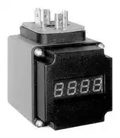
PHX20-A
Plug-On Display, 4 Digit, 7.62 mm, 0 to 60 °C, PHX20 Series
⚠️ Reference pricing provided. In case of supply shortages, we will connect you with our trusted procurement partners to ensure your project's continuity.
- Manufacturer: ENDRESS+HAUSER
- Product type: Digital Panel Meters
- SVHC: To Be Advised
- Meter Range: -1999 to 9999
- Digit Height: 7.62mm
- Product Range: PHX20 Series
- Meter Function: -
- Panel Cutout Width: -
- Supply Voltage Max: -
- Supply Voltage Min: -
- Panel Cutout Height: -
- No. of Digits / Alpha: 4
- Operating Temperature Max: 60°C
- Operating Temperature Min: 0°C
| Delivery and price | |
|---|---|
| Units per pack | 1 |
| Price | 150.8 € |
| Current stock | 10+ |
| Lead time | 30 days |
Datasheet

BA01271P/00/EN/03.16 71336273 Products Solutions Services ## Operating Instructions Cerabar PMP11, PMP21, PMP23 Process pressure measurement Pressure transducer for safe measurement and monitoring of absolute and gauge pressure **==> picture [34 x 140] intentionally omitted <==** **==> picture [267 x 264] intentionally omitted <==** **----- Start of picture text -----**<br> Order code: XXXXX-XXXXXX<br>1. <0» Ser. no.: XXXXXXXXXXXX<br>S Ext. ord. cd.: XXX.XXXX.XX<br>es Ss<br>=<br>Serial number<br>2. www.endress.com/deviceviewer Endress+Hauser<br>Operations App<br>4 Download on the<br>7 ee MNa>4 ik pi“4 > GoogleANDROID APP ON Play<br>3.<br>**----- End of picture text -----**<br> **==> picture [22 x 4] intentionally omitted <==** **----- Start of picture text -----**<br> A0023555<br>**----- End of picture text -----**<br> - Make sure the document is stored in a safe place such that it is always available when working on or with the device. - To avoid danger to individuals or the facility, read the "Basic safety instructions" section carefully, as well as all other safety instructions in the document that are specific to working procedures. - The manufacturer reserves the right to modify technical data without prior notice. Your Endress+Hauser distributor will supply you with current information and updates to these Instructions. Endress+Hauser 2 Table of contents ## Table of contents |1|Document information . . . . . . . . . . . . . .||4| |---|---|---|---| |1.1|Document function. . . . . . . . . . . . . . . . . . . . .||4| |1.2|Symbols used. . . . . . . . . . . . . . . . . . . . . . . . . .||4| |1.3|Documentation. . . . . . . . . . . . . . . . . . . . . . . .||5| |1.4|Terms and abbreviations. . . . . . . . . . . . . . . . .||7| |1.5|Turn down calculation. . . . . . . . . . . . . . . . . . .||8| |2|Basic safety instructions . . . . . . . . . . . .||9| |2.1|Requirements concerning the staff. . . . . . . . . .||9| |2.2|Designated use. . . . . . . . . . . . . . . . . . . . . . . .||9| |2.3|Workplace safety. . . . . . . . . . . . . . . . . . . . . .||10| |2.4<br>2.5|Operational safety. . . . . . . . . . . . . . . . . . . . .<br>Product safety. . . . . . . . . . . . . . . . . . . . . . . .||10<br>10| |3|Product description . . . . . . . . . . . . . . . .|11|| |3.1|Product design. . . . . . . . . . . . . . . . . . . . . . . .||11| |3.2|Function. . . . . . . . . . . . . . . . . . . . . . . . . . . .||11| |4|Incoming acceptance and product||| ||identification . . . . . . . . . . . . . . . . . . . . .|12|| |4.1|Incoming acceptance. . . . . . . . . . . . . . . . . . .||12| |4.2|Product identification. . . . . . . . . . . . . . . . . . .||13| |4.3|Storage and transport. . . . . . . . . . . . . . . . . .||13| |5|Installation . . . . . . . . . . . . . . . . . . . . . . .|15|| |5.1|Mounting dimensions. . . . . . . . . . . . . . . . . .||15| |5.2|Installation conditions. . . . . . . . . . . . . . . . . .||15| |5.3|Influence of the installation position. . . . . . . .||15| |5.4|Mounting location. . . . . . . . . . . . . . . . . . . . .||16| |5.5|Mounting the profiled seal for the universal||| ||process adapter. . . . . . . . . . . . . . . . . . . . . . .||17| |5.6|Post-installation check. . . . . . . . . . . . . . . . . .||17| |6|Electrical connection . . . . . . . . . . . . . .|18|| |6.1|Connecting the measuring unit. . . . . . . . . . . .||18| |6.2|Connection conditions. . . . . . . . . . . . . . . . . .||19| |6.3|Connection data. . . . . . . . . . . . . . . . . . . . . . .||19| |6.4|Post-connection check. . . . . . . . . . . . . . . . . .||20| |7|Operation options . . . . . . . . . . . . . . . . .|21|| |7.1|Plug-on display PHX20 (optional). . . . . . . . . .||21| |8|Diagnostics and troubleshooting . . .|24|| |8.1|Troubleshooting. . . . . . . . . . . . . . . . . . . . . .||24| |8.2|Response of output to errors. . . . . . . . . . . . . .||24| |8.3|Disposal. . . . . . . . . . . . . . . . . . . . . . . . . . . .||24| |9|Maintenance . . . . . . . . . . . . . . . . . . . . . .|24|| |9.1|Exterior cleaning. . . . . . . . . . . . . . . . . . . . . .||25| |10|Repair . . . . . . . . . . . . . . . . . . . . . . . . . . . .|26| |---|---|---| |10.1|General notes. . . . . . . . . . . . . . . . . . . . . . . .|26| |10.2|Return. . . . . . . . . . . . . . . . . . . . . . . . . . . . . .|26| |11|Accessories . . . . . . . . . . . . . . . . . . . . . . .|27| |11.1|Weld-in adapter. . . . . . . . . . . . . . . . . . . . . .|27| |11.2|Process adapter M24. . . . . . . . . . . . . . . . . . .|27| |11.3|Plug-on display PHX20. . . . . . . . . . . . . . . . .|28| |11.4|M12 plug connectors. . . . . . . . . . . . . . . . . . .|28| |12|Technical data . . . . . . . . . . . . . . . . . . . .|29| |12.1|Input. . . . . . . . . . . . . . . . . . . . . . . . . . . . . . .|29| |12.2|Output. . . . . . . . . . . . . . . . . . . . . . . . . . . . .|31| |12.3|Performance characteristics of metallic|| ||process isolating diaphragm. . . . . . . . . . . . . .|33| |12.4|Environment. . . . . . . . . . . . . . . . . . . . . . . . .|35| |12.5|Process. . . . . . . . . . . . . . . . . . . . . . . . . . . . .|37| |Index . . . . . . . . . . . . . . . . . . . . . . . . . . . . . . . . . .||38| Endress+Hauser 3 Cerabar PMP11, PMP21, PMP23 Document information ## 1 Document information ## 1.1 Document function These Operating Instructions contain all the information that is required in various phases of the life cycle of the device: from product identification, incoming acceptance and storage, to mounting, connection, operation and commissioning through to troubleshooting, maintenance and disposal. ## 1.2 Symbols used ## 1.2.1 Safety symbols |Symbol|Meaning| |---|---| |**DANGER**|DANGER!<br>This symbol alerts you to a dangerous situation. Failure to avoid this situation will result in<br>serious or fatal injury.| |**WARNING**|WARNING!<br>This symbol alerts you to a dangerous situation. Failure to avoid this situation can result in<br>serious or fatal injury.| |**CAUTION**|CAUTION!<br>This symbol alerts you to a dangerous situation. Failure to avoid this situation can result in<br>minor or medium injury.| |**NOTICE**|NOTE!<br>This symbol contains information on procedures and other facts which do not result in<br>personal injury.| ## 1.2.2 Electrical symbols |Symbol|Symbol|Meaning|Symbol|Meaning| |---|---|---|---|---| |||Protective ground connection<br>A terminal which must be connected<br>to ground prior to establishing any<br>other connections.||Ground connection<br>A grounded terminal which, as far as<br>the operator is concerned, is<br>grounded via a grounding system.| |1.2.3<br>Tool symbols||||| |Symbol|Meaning|||| |A0011222|Open-ended wrench|||| ## 1.2.4 Symbols for certain types of information |Symbol|Meaning| |---|---| ||Permitted<br>Procedures, processes or actions that are permitted.| ||Forbidden<br>Procedures, processes or actions that are forbidden.| ||Tip<br>Indicates additional information.| Endress+Hauser 4 Cerabar PMP11, PMP21, PMP23 Document information |Symbol|Meaning| |---|---| ||Reference to documentation| |**A**|Reference to page| ||Reference to graphic| |,<br>…<br>,<br>1. 2. 3.|Series of steps| ||Result of a step| ||Visual inspection| ## 1.2.5 Symbols in graphics |Symbol|Meaning| |---|---| |1, 2, 3 ...|Item numbers| |,<br>…<br>,<br>1. 2. 3.|Series of steps| |A, B, C, ...|Views| ## 1.3 Documentation The document types listed are available: In the Download Area of the Endress+Hauser Internet site: www.endress.com → Download ## 1.3.1 Technical Information (TI): planning aid for your device PMP11: TI01133P PMP21: TI01133P PMP23: TI01203P The document contains all the technical data on the device and provides an overview of the accessories and other products that can be ordered for the device. ## 1.3.2 Brief Operating Instructions (KA): getting the 1st measured value quickly ## KA01164P: The Brief Operating Instructions contain all the essential information from incoming acceptance to initial commissioning. ## 1.3.3 Safety Instructions (XA) Safety Instructions (XA) are supplied with the device depending on the approval. These instructions are an integral part of the Operating Instructions. |Device|Directive|Documentation|Option1)| |---|---|---|---| |PMP21<br>PMP23|ATEX II 1/2G Ex ia IIC T4 Ga/Gb|XA01271P|BA| |PMP21|ATEX II 3G Ex ec IIC T4 Gc|XA01533P|BC| |PMP21<br>PMP23|FM IS Cl. I, Div.1 Gr. A-D T4|XA01321P|FA| Endress+Hauser 5 Cerabar PMP11, PMP21, PMP23 Document information |Device|Directive|Documentation|Option1)| |---|---|---|---| |PMP21<br>PMP23|CSA C/US IS Cl. I Div. 1 Gr. A-D|XA01322P|CB| |PMP21<br>PMP23|EAC Ex ia IIC T4 Ga/Gb|XA01540P|GA| |PMP21<br>PMP23|IEC Ex ia IIC T4 Ga/Gb|XA01271P|IA| |PMP21<br>PMP23|NEPSI Ex ia IIC T4|XA01363P|NA| |PMP21<br>PMP23|TIIS Ex ia IIC T4|In preparation|TA| - 1) Product Configurator, order code for "Approval" The nameplate provides information on the Safety Instructions (XA) that are relevant for the device. Endress+Hauser 6 Cerabar PMP11, PMP21, PMP23 Document information ## 1.4 Terms and abbreviations |1.4<br>Terms and abbreviations|1.4<br>Terms and abbreviations|1.4<br>Terms and abbreviations| |---|---|---| |URL<br>OPL<br>MWP<br>LRL<br>0<br>p<br>LRV<br>URV<br>1<br>2<br>3<br>4||| |A0029505||| |Item|Term/<br>abbreviation|Explanation| |1|OPL|The OPL (over pressure limit = sensor overload limit) for the measuring device<br>depends on the lowest-rated element, with regard to pressure, of the selected<br>components, i.e. the process connection has to be taken into consideration in<br>addition to the measuring cell. Also observe pressure-temperature dependency. For<br>the relevant standards and additional notes, see the "Pressure specifications" section<br>→ 37 .<br>The OPL may only be applied for a limited period of time.| |2|MWP|The MWP (maximum working pressure) for the sensors depends on the lowest-<br>rated element, with regard to pressure, of the selected components, i.e. the process<br>connection has to be taken into consideration in addition to the measuring cell.<br>Also observe pressure-temperature dependency. For the relevant standards and<br>additional notes, see the "Pressure specifications" section → 37 .<br>The MWP may be applied at the device for an unlimited period.<br>The MWP can also be found on the nameplate.| |3|Maximum sensor<br>measuring range|Span between LRL and URL<br>This sensor measuring range is equivalent to the maximum calibratable/adjustable<br>span.| |4|Calibrated/<br>adjusted span|Span between LRV and URV<br>Factory setting: 0 to URL<br>Other calibrated spans can be ordered as customized spans.| |p|-|Pressure| |-|LRL|Lower range limit| |-|URL|Upper range limit| |-|LRV|Lower range value| |-|URV|Upper range value| |-|TD (turn down)|Turn down<br>The turn down is preset at the factory and cannot be changed.<br>Example - see the following section.| Endress+Hauser 7 Cerabar PMP11, PMP21, PMP23 Document information ## 1.5 Turn down calculation **==> picture [387 x 94] intentionally omitted <==** **----- Start of picture text -----**<br> 1 = 2 3<br>LRL LRV URV URL<br> A0029545<br>1 Calibrated/adjusted span<br>2 Zero point-based span<br>3 URL sensor<br>**----- End of picture text -----**<br> Example • Sensor:10 bar (150 psi) • Calibrated/adjusted span: 0 to 5 bar (0 to 75 psi) • Upper range value (URL) = 10 bar (150 psi) • Lower range value (LRV) = 0 bar (0 psi) • Upper range value (URV) = 5 bar (75 psi) Turn down (TD): URL TD = |URV - LRV| 10 bar (150 psi) TD = = 2 - |5 bar (75 psi) 0 bar (0 psi)| In this example, the TD is 2:1. This span is based on the zero point. Endress+Hauser 8 Cerabar PMP11, PMP21, PMP23 Basic safety instructions ## 2 Basic safety instructions ## 2.1 Requirements concerning the staff The personnel for installation, commissioning, diagnostics and maintenance must fulfill the following requirements: - ‣ Trained, qualified specialists: must have a relevant qualification for this specific function and task - ‣ Are authorized by the plant owner/operator - ‣ Are familiar with federal/national regulations - ‣ Before beginning work, the specialist staff must have read and understood the instructions in the Operating Instructions and supplementary documentation as well as in the certificates (depending on the application) - ‣ Following instructions and basic conditions The operating personnel must fulfill the following requirements: - ‣ Being instructed and authorized according to the requirements of the task by the facility's owner-operator - ‣ Following the instructions in these Operating Instructions ## 2.2 Designated use ## 2.2.1 Application and media The Cerabar is used to measure absolute and gauge pressure in gases, vapors and liquids. The process-wetted materials of the measuring device must have an adequate level of resistance to the media. The measuring device may be used for the following measurements (process variables) - in compliance with the limit values specified under "Technical data" - in compliance with the conditions that are listed in additional documentation such as the XA and this manual. ## Measured process variable - PMP11: gauge pressure - PMP21: gauge pressure or absolute pressure - PMP23: gauge pressure or absolute pressure ## Calculated process variable Pressure ## 2.2.2 Incorrect use The manufacturer is not liable for damage caused by improper or non-designated use. Verification for borderline cases: - ‣ For special fluids and fluids for cleaning, Endress+Hauser is glad to provide assistance in verifying the corrosion resistance of process-wetted materials, but does not accept any warranty or liability. ## 2.2.3 Residual risks When in operation, the housing may reach a temperature close to the process temperature. Danger of burns from contact with surfaces! - ‣ For elevated process temperatures, ensure protection against contact to prevent burns. Endress+Hauser 9 Cerabar PMP11, PMP21, PMP23 Basic safety instructions ## 2.3 Workplace safety For work on and with the device: - ‣ Wear the required personal protective equipment according to federal/national regulations. - ‣ Switch off the supply voltage before connecting the device. ## 2.4 Operational safety Risk of injury! - ‣ Operate the device in proper technical condition and fail-safe condition only. - ‣ The operator is responsible for interference-free operation of the device. ## Conversions to the device Unauthorized modifications to the device are not permitted and can lead to unforeseeable dangers. - ‣ If, despite this, modifications are required, consult with Endress+Hauser. ## Hazardous area To eliminate the risk of danger to persons or the facility when the device is used in the approval-related area (e.g. explosion protection, pressure equipment safety): - ‣ Check the nameplate to verify if the device ordered can be put to its intended use in the approval-related area. - ‣ Observe the specifications in the separate supplementary documentation, such as the XA or SD, which is an integral part of these Instructions. ## 2.5 Product safety This measuring device is designed in accordance with good engineering practice to meet state-of-the-art safety requirements, has been tested, and left the factory in a condition in which it is safe to operate. It meets general safety standards and legal requirements. It also complies with the EU directives listed in the device-specific EU Declaration of Conformity. Endress+Hauser confirms this by affixing the CE mark to the device. Endress+Hauser 10 Cerabar PMP11, PMP21, PMP23 Product description ## 3 Product description ## 3.1 Product design **==> picture [517 x 373] intentionally omitted <==** **----- Start of picture text -----**<br> Overview Item Description<br>A B C - 1 C - 2 A Valve plug<br>B Cable<br>C- 1 M12 plug<br>Housing cap made of plastic<br>C- 2 M12 plug<br> A0027231 A0027232 A0021987 A0027289 For Ex eC and IP69: metal housing cap<br>Metal housing cap can also be ordered as an option.<br>D D Housing<br>E Process connection (sample illustration)<br>E<br> A0027215<br>D<br>E<br> A0027227<br>**----- End of picture text -----**<br> ## 3.2 Function ## 3.2.1 Calculating the pressure ## Devices with metallic process isolating diaphragm The process pressure deflects the metal process isolating diaphragm of the sensor and a fill fluid transfers the pressure to a Wheatstone bridge (semiconductor technology). The pressure-dependent change in the bridge output voltage is measured and evaluated. Endress+Hauser 11 Incoming acceptance and product identification Cerabar PMP11, PMP21, PMP23 ## 4 Incoming acceptance and product identification ## 4.1 Incoming acceptance **==> picture [145 x 42] intentionally omitted <==** **----- Start of picture text -----**<br> DELIVERY NOTE<br> A0028673<br>——<br>1 = 2<br>**----- End of picture text -----**<br> **==> picture [22 x 4] intentionally omitted <==** **----- Start of picture text -----**<br> A0016870<br>**----- End of picture text -----**<br> Is the order code on the delivery note (1) identical to the order code on the product sticker (2)? **==> picture [22 x 4] intentionally omitted <==** **----- Start of picture text -----**<br> A0022100<br>**----- End of picture text -----**<br> **==> picture [22 x 3] intentionally omitted <==** **----- Start of picture text -----**<br> A0028673<br>**----- End of picture text -----**<br> **==> picture [22 x 3] intentionally omitted <==** **----- Start of picture text -----**<br> A0022103<br>**----- End of picture text -----**<br> Are the goods undamaged? **==> picture [86 x 6] intentionally omitted <==** **----- Start of picture text -----**<br> A0028673 DELIVERY NOTE<br>**----- End of picture text -----**<br> **==> picture [22 x 4] intentionally omitted <==** **----- Start of picture text -----**<br> A0022105<br>**----- End of picture text -----**<br> Do the data on the nameplate correspond to the order specifications and the delivery note? Endress+Hauser 12 Cerabar PMP11, PMP21, PMP23 Incoming acceptance and product identification **==> picture [22 x 4] intentionally omitted <==** **----- Start of picture text -----**<br> A0028673<br>**----- End of picture text -----**<br> **==> picture [22 x 4] intentionally omitted <==** **----- Start of picture text -----**<br> A0022106<br>**----- End of picture text -----**<br> Is the documentation available? If required (see nameplate): Are the safety instructions (XA) present? If one of these conditions does not apply, please contact your Endress+Hauser sales office. ## 4.2 Product identification The following options are available for identification of the measuring device: - Nameplate specifications - Order code with breakdown of the device features on the delivery note - Enter serial numbers from nameplates in _W@M Device Viewer_ (www.endress.com/deviceviewer): All information about the measuring device is displayed. For an overview of the technical documentation provided, enter the serial number from the nameplates in the _W@M Device Viewer_ (www.endress.com/deviceviewer) ## 4.2.1 Nameplate **==> picture [255 x 127] intentionally omitted <==** **----- Start of picture text -----**<br> 12 Fy Endress+Hauser Cerabar Cai)<br>Made in Germany,<br>D-79689 Maulburg<br>3 Ord. cd.:<br>4 Ser. no.:<br>5 —t Ext. ord. cd.:<br>A<br>Date:<br>TAG:<br>bi<br> A0024456<br>**----- End of picture text -----**<br> - _1 Manufacturer's address_ - _2 Device name_ - _3 Order number_ - _4 Serial number_ - _5 Extended order number_ ## 4.3 Storage and transport ## 4.3.1 Storage conditions Use original packaging. Store the measuring device in clean and dry conditions and protect from damage caused by shocks (EN 837-2). Storage temperature range –40 to +85 °C (–40 to +185 °F) Endress+Hauser 13 Incoming acceptance and product identification Cerabar PMP11, PMP21, PMP23 ## 4.3.2 Transporting the product to the measuring point ## L[WARNING] ## Incorrect transport! Housing and diaphragm may become damaged, and there is a risk of injury! - ‣ Transport the measuring device to the measuring point in its original packaging or by the process connection. Endress+Hauser 14 Cerabar PMP11, PMP21, PMP23 Installation ## 5 Installation ## 5.1 Mounting dimensions For dimensions, see the "Mechanical construction" section in the Technical Information. ## 5.2 Installation conditions - No moisture may enter the housing when installing or operating the device, or when establishing the electrical connection. - For metal M12 plugs: Do not remove the protection cap (only for IP69 and Ex ec version) of the M12 plug terminal until shortly before the electrical connection. - Do not clean or touch process isolating diaphragms with hard and/or pointed objects. - Do not remove the protector on the process isolating diaphragm until just before installation. - Always firmly tighten the cable entry. - Point the cable and connector downwards where possible to prevent moisture from entering (e.g. rain or condensation water). - Protect the housing from impact - The following instruction applies for devices with a gauge pressure sensor and M12 plug or valve plug: ## NOTICE If a heated device is cooled during the cleaning process (e.g. by cold water), a vacuum develops for a short time, whereby moisture can penetrate the sensor through the pressure compensation element (1). Device could be destroyed! - ‣ In this case, mount the device with the pressure compensation element (1) pointing diagonally downwards where possible or to the side. **==> picture [234 x 66] intentionally omitted <==** **----- Start of picture text -----**<br> 1<br>1 1 1<br>**----- End of picture text -----**<br> **==> picture [22 x 4] intentionally omitted <==** **----- Start of picture text -----**<br> A0022252<br>**----- End of picture text -----**<br> ## 5.3 Influence of the installation position Any orientation is possible. However, the orientation may cause a zero point shift i.e. the measured value does not show zero when the vessel is empty or partially full. **A B C** **==> picture [22 x 4] intentionally omitted <==** **----- Start of picture text -----**<br> A0024708<br>**----- End of picture text -----**<br> |Process isolating diaphragm axis<br>is horizontal (A)|Process isolating diaphragm<br>pointing upwards (B)|Process isolating diaphragm<br>pointing downwards (C)| |---|---|---| |Calibration position, no effect|Up to +4 mbar (+0.058 psi)|Up to –4 mbar (–0.058 psi)| Endress+Hauser 15 Installation Cerabar PMP11, PMP21, PMP23 ## 5.4 Mounting location ## 5.4.1 Pressure measurement The pressure measurement specifications only apply for PMP11 and PMP21 devices. ## Pressure measurement in gases Mount the device with shutoff device above the tapping point so that any condensate can flow into the process. **==> picture [387 x 107] intentionally omitted <==** **----- Start of picture text -----**<br> 1<br>2<br> A0021904<br>**----- End of picture text -----**<br> **==> picture [66 x 19] intentionally omitted <==** **----- Start of picture text -----**<br> 1 Device<br>2 Shutoff device<br>**----- End of picture text -----**<br> ## Pressure measurement in vapors For pressure measurement in vapors, use a siphon. The siphon reduces the temperature to almost ambient temperature. Mount the device with a shutoff device at the same height as the tapping point. Advantage: only minor/negligible heat effects on the device. Note the max. permitted ambient temperature of the transmitter! **==> picture [387 x 140] intentionally omitted <==** **----- Start of picture text -----**<br> 1<br>2<br>3<br> A0024395<br>**----- End of picture text -----**<br> **==> picture [40 x 7] intentionally omitted <==** **----- Start of picture text -----**<br> 1 Device<br>**----- End of picture text -----**<br> _2 Shutoff device 3 Siphon_ ## Pressure measurement in liquids Mount the device with a shutoff device at the same height as the tapping point. Endress+Hauser 16 Cerabar PMP11, PMP21, PMP23 Installation **==> picture [29 x 7] intentionally omitted <==** **----- Start of picture text -----**<br> 2 1<br>**----- End of picture text -----**<br> **==> picture [22 x 4] intentionally omitted <==** **----- Start of picture text -----**<br> A0024399<br>**----- End of picture text -----**<br> **==> picture [66 x 19] intentionally omitted <==** **----- Start of picture text -----**<br> 1 Device<br>2 Shutoff device<br>**----- End of picture text -----**<br> ## 5.4.2 Level measurement - Always install the device below the lowest measuring point. - Do not install the device at the following positions: - In the filling curtain - In the tank outlet - In the suction area of a pump - Or at a point in the tank which could be affected by pressure pulses from the agitator. **==> picture [57 x 36] intentionally omitted <==** **==> picture [156 x 61] intentionally omitted <==** **==> picture [22 x 4] intentionally omitted <==** **----- Start of picture text -----**<br> A0024405<br>**----- End of picture text -----**<br> ## 5.5 Mounting the profiled seal for the universal process adapter For details on mounting, see KA00096F/00/A3. ## 5.6 Post-installation check - Is the device undamaged (visual inspection)? Does the device conform to the measuring point specifications? For example: - • Process temperature • Process pressure • Ambient temperature range • Measuring range - Are the measuring point identification and labeling correct (visual inspection)? Is the device adequately protected from precipitation and direct sunlight? Are the securing screws tightened securely? Does the pressure compensation element point downwards at an angle or to the side? To prevent the penetration of moisture: are the connecting cables/plugs pointing downwards? Endress+Hauser 17 Electrical connection Cerabar PMP11, PMP21, PMP23 ## 6 Electrical connection ## 6.1 Connecting the measuring unit ## 6.1.1 Terminal assignment ## L[WARNING] Risk of injury from the uncontrolled activation of processes! - ‣ Switch off the supply voltage before connecting the device. - ‣ Make sure that downstream processes are not started unintentionally. ## L[WARNING] Supply voltage might be connected! Risk of explosion! - ‣ Make sure that no supply voltage is applied when connecting. - ‣ Switch off the supply voltage before connecting the device. ## L[WARNING] Limitation of electrical safety due to incorrect connection! - ‣ In accordance with IEC/EN61010 a separate circuit breaker must be provided for the device . - ‣ The device must be operated with a 500 mA fine-wire fuse (slow-blow). - ‣ When using the measuring device in hazardous areas, installation must comply with the corresponding national standards and regulations and the Safety Instructions or Installation or Control Drawings. - ‣ All explosion protection data are given in separate documentation which is available upon request. The Ex documentation is supplied as standard with all devices approved for use in explosion hazardous areas. - ‣ Protective circuits against reverse polarity are integrated. Connect the device in the following order: 1. Check whether the supply voltage matches the supply voltage indicated on the nameplate. 2. Connect device in accordance with the following diagram. Switch on supply voltage. For devices with a cable connection: do not close reference air hose (see (a) in the following drawings)! Protect reference air hose against penetration by water/condensate. ## _4 to 20 mA output_ **==> picture [387 x 142] intentionally omitted <==** **----- Start of picture text -----**<br> Device M12 plug Valve plug Cable<br>PMP11 0.5A 0.5A 1 0.5A<br>PMP21 L+ 1 L+ L+<br>2 1<br>PMP23 3 2<br>3 4 L–<br>L– 3<br>2<br> A0023487 L– (a)<br> A0022823 A0023783<br>1 brown = L+<br>2 blue = L-<br>3 green/yellow = ground connection<br>(a) reference air hose<br>**----- End of picture text -----**<br> Endress+Hauser 18 Cerabar PMP11, PMP21, PMP23 Electrical connection ## _0 to 10 V output_ **==> picture [387 x 101] intentionally omitted <==** **----- Start of picture text -----**<br> Device M12 plug Valve plug Cable<br>PMP11 0.5A 1 -<br>L+<br>3<br>2 1<br>4<br>3<br>2 L–<br>L–<br> A0017576 0.5A L+<br> A0022822<br>**----- End of picture text -----**<br> ## 6.1.2 Supply voltage ## L[WARNING] ## Supply voltage might be connected! Risk of explosion! - ‣ When using the measuring device in hazardous areas, installation must comply with the corresponding national standards and regulations as well as the Safety Instructions. - ‣ All explosion protection data are given in separate documentation which is available upon request. The Ex documentation is supplied as standard with all devices approved for use in explosion hazardous areas. |Electronic version|Device|Supply voltage| |---|---|---| |4 to 20 mA output|PMP11<br>PMP21<br>PMP23|10 to 30 V DC| |0 to 10 V output|PMP11|12 to 30 V DC| ## 6.1.3 Current consumption and alarm signal |Number of wires|Device|Normal operation|Alarm signal1)| |---|---|---|---| |2|PMP11<br>PMP21<br>PMP23|≤ 26 mA|> 21 mA| |3|PMP11|< 12 mA|11 V| 1) For MAX alarm (factory setting) ## 6.2 Connection conditions ## 6.2.1 Cable specification For valve plug: < 1.5 mm[2] (16 AWG) and Ø3.5 to 6.5 mm (0.14 to 0.26 in) ## 6.3 Connection data ## 6.3.1 Load (for 4 to 20 mA devices ) In order to guarantee sufficient terminal voltage in two-wire devices, a maximum load resistance RL (including line resistance) must not be exceeded, depending on the supply voltage UB of the supply unit. Endress+Hauser 19 Electrical connection Cerabar PMP11, PMP21, PMP23 **==> picture [387 x 133] intentionally omitted <==** **----- Start of picture text -----**<br> RLmax<br>[�]<br>1068<br>614 2 RLmax � U B � 6.5V<br>22mA<br>10 20 30 UB<br>[V]<br>1<br> A0029452<br>**----- End of picture text -----**<br> - _1 Power supply 10 to 30 V DC 2 RLmax maximum load resistance UB Supply voltage_ ## 6.3.2 Load resistance (for 0 to 10 V devices) The load resistance must be ≥ 5 [kΩ]. ## 6.4 Post-connection check |6.4|<br>Post-connection check| |---|---| ||Is the device or cable undamaged (visual check)?| ||Do the cables comply with the requirements ?| ||Do the cables have adequate strain relief?| ||Are all the cable glands installed, firmly tightened and leak-tight?| ||Does the supply voltage match the specifications on the nameplate?| ||Is the terminal assignment correct ?| ||If required: Has protective ground connection been established ?| Endress+Hauser 20 Cerabar PMP11, PMP21, PMP23 Operation options ## 7 Operation options ## 7.1 Plug-on display PHX20 (optional) No display or other operation facility is required to operate the device. However, devices with a valve plug can be fitted with the optional local display PHX20. A 1-line liquid crystal display (LCD) is used. The local display shows measured values, fault messages and information messages. The device display can be turned in 90° steps. Depending on the orientation of the device, it is therefore easy to read the measured values. ## 7.1.1 Storage conditions - Use original packaging. - Storage temperature range: –30 to +80 °C (–22 to +176 °F) ## 7.1.2 Installation **==> picture [387 x 88] intentionally omitted <==** **----- Start of picture text -----**<br> 1 2 3 4<br> A0022208<br>**----- End of picture text -----**<br> 1. Place seals between the sensor/plug-on display and the plug-on display/connector. 2. Fit the plug-on display (2) between the connector (3) and connector socket (1) of the sensor. 3. Replace the securing screw (4) with the longer screw included in the delivery. 4. An adhesive label (included in the delivery) with information on the technical unit can be fixed beneath the LED display. ## Mounting dimensions **==> picture [162 x 102] intentionally omitted <==** **----- Start of picture text -----**<br> 42 (1.65) 48 (1.89)<br>42 (1.65)<br>**----- End of picture text -----**<br> **==> picture [22 x 4] intentionally omitted <==** **----- Start of picture text -----**<br> A0022210<br>**----- End of picture text -----**<br> ## 7.1.3 Technical data |7.1.3<br>Technical data|| |---|---| |Display:<br>4-|digit, red LED display| |Digit height:<br>7.6|2 mm; programmable decimal point setting| |Display range:<br>-1|999 to 9999| |Accuracy:<br>0.2|% of the span ±1 digit| Endress+Hauser 21 Cerabar PMP11, PMP21, PMP23 Operation options |Electrical connection:|To transmitter with 4 to 20 mA output and elbow plug DIN 43 650,<br>reverse polarity protection| |---|---| |Display power supply:|Not required, powered automatically from the power loop| |Voltage drop:|≤ 5 V (corresponds to load: max. 250 Ω)| |Rate of conversion:|3 measurements per second| |Damping:|0.3 to 20 s (configurable)| |Data backup:|Non-volatile EEPROM| |Error message:|• HI: overrange<br>• LO: below range| |Programming:|Via 2 keys, menu-guided, display range scaling, decimal point, damping,<br>error message| |Degree of protection:|IP 65| |Influence of temperature on the<br>display:|0.1% / 10 K| |Electromagnetic compatibility<br>(EMC):|Interference emission as per EN 50081, interference immunity as per EN<br>50082| |Permitted current load:|Max. 60 mA| |Ambient temperature:|0 to +60 °C (+32 to +140 °F)| |Housing material:|Pa6 GF30 plastic, blue<br>Front screen made from red PMMA| |Order number:|52022914| ## 7.1.4 Electrical connection ## Pin assignment ## L[WARNING] Is the supply voltage switched off? Risk of electric shock! - ‣ Switch off the supply voltage before connecting the device. - PIN 1: L+ (supply voltage UB) - PIN 2: L- (0 V) - PIN 3: Not assigned ## Supply voltage The supply voltage (mostly 24 V DC) must be greater than the sum of the voltage drop Us at the sensor, the voltage drop of 5 V at the display and other voltage loss Ua (such as additional evaluation and power loss). The following therefore applies: Ub = Us + 5 V + Ua ## Post-connection check Is the device or cable undamaged (visual check)? Are all cable glands installed, securely tightened and leak-tight? If supply voltage is present, is the device ready for operation and do values appear on the display module? Endress+Hauser 22 Cerabar PMP11, PMP21, PMP23 Operation options ## 7.1.5 Commissioning ## NOTICE Risk of injury from the uncontrolled activation of processes! - ‣ Ensure that no uncontrolled processes are activated in the system. ## Configuring the menu items To configure the menu items, loosen the 4 Phillips screws (1) on the display and remove the cover. **==> picture [90 x 65] intentionally omitted <==** **----- Start of picture text -----**<br> 1 1<br>A B<br>1 1<br>**----- End of picture text -----**<br> **==> picture [22 x 4] intentionally omitted <==** **----- Start of picture text -----**<br> A0022209<br>**----- End of picture text -----**<br> - _A Move down and select the items_ - _B Move up and select the items_ _A+B Select the item to configure or acknowledge the setting_ ## Setting the decimal point |Setting the decimal point||| |---|---|---| |||| |Press the B key until "dP" is displayed.||d<br>P| |Press A+B to set the decimal point:||-<br>-<br>-.<br>-| |Press B or A for up or down:||-<br>-.<br>-<br>-| |Press A+B to quit the setting function and to go to the "dP" menu item.||d<br>P| ## Out of range setting Message if signal is below 4 mA or above 20 mA: - "HI" message = over range - "LO" message = below range |Out of range setting<br>Message if signal is below 4 mA or above 20 mA:<br>• "HI" message = over range<br>• "LO" message = below range||| |---|---|---| |||| |Press the B key until "HILO" is displayed.||H<br>I<br>L<br>O| |Press A+B for the setting function (message inactive):||o<br>F<br>F| |Press B or A for up or down (message active):||o<br>n| |Press A+B to quit the setting function and to go to the "HILO" menu item.||H<br>I<br>L<br>O| Please note: If the "HILO" message is not active, the error "Er06" is displayed if the display range (-1999 to +9999) is exceeded. ## Changing to the measuring mode Depending on the menu item selected, press key A or B between 1 and 8 times. Endress+Hauser 23 Diagnostics and troubleshooting Cerabar PMP11, PMP21, PMP23 ## 8 Diagnostics and troubleshooting ## 8.1 Troubleshooting If an illegal configuration exists in the device, the device switches to error mode. ## _General errors_ |Error|Possible cause|Solution| |---|---|---| |Device is not responding.|Supply voltage does not match that specified on<br>the nameplate.|Apply correct voltage.| ||Supply voltage has incorrect polarity.|Reverse polarity of supply voltage.| ||Connecting cables are not in contact with the<br>terminals.|Check the contacting of the cables<br>and correct if necessary.| |Output current<br>≤ 3.6 mA|Signal line is not wired correctly.|Check wiring.| ## 8.2 Response of output to errors The response of the output to error is regulated in accordance with NAMUR NE43. Factory setting MAX alarm: >21 mA ## 8.2.1 alarm current |Device|Description|Option| |---|---|---| |PMP21<br>PMP23|Adjusted min. alarm current|IA1)| 1) Product Configurator order code for "Service" ## 8.3 Disposal When disposing, separate and recycle the device components based on the materials. ## 9 Maintenance No special maintenance work is required. Keep the pressure compensation element (1) free from contamination. **==> picture [37 x 7] intentionally omitted <==** **----- Start of picture text -----**<br> 1<br>**----- End of picture text -----**<br> A0022141 Endress+Hauser 24 Cerabar PMP11, PMP21, PMP23 Maintenance ## 9.1 Exterior cleaning Please note the following points when cleaning the device: - The cleaning agents used should not corrode the surface and the seals. - Mechanical damage to the process isolating diaphragm, e.g. due to sharp objects, must be avoided. - Observe the degree of protection of the device. See the nameplate if necessary → 13. Endress+Hauser 25 Cerabar PMP11, PMP21, PMP23 Repair ## 10 Repair ## 10.1 General notes ## 10.1.1 Repair concept Repairs are not possible. ## 10.2 Return The measuring device must be returned if the wrong device has been ordered or delivered. As an ISO-certified company and also due to legal regulations, Endress+Hauser is obliged to follow certain procedures when handling any returned products that have been in contact with medium. To ensure swift, safe and professional device returns, please read the return procedures and conditions on the Endress+Hauser website at www.services.endress.com/return-material Endress+Hauser 26 Cerabar PMP11, PMP21, PMP23 Accessories ## 11 Accessories ## 11.1 Weld-in adapter Various weld-in adapters are available for installation in vessels or pipes. |Device|Description|Option1)|Order number| |---|---|---|---| |PMP23|Weld-in adapter M24, d=65, 316L|PM|71041381| |PMP23|Weld-in adapter M24, d=65, 316L 3.1 EN10204-3.1<br>material, inspection certificate|PN|71041383| |PMP21|Weld-in adapter G½, 316L|QA|52002643| |PMP21|Weld-in adapter G½, 316L 3.1 EN10204-3.1 material,<br>inspection certificate|QB|52010172| |PMP21|Weld-in tool adapter G½, brass|QC|52005082| |PMP23|Weld-in adapter G1, 316L, conical metal joint|QE|52005087| |PMP23|Weld-in adapter G1, 316L, 3.1, conical metal joint,<br>EN10204-3.1 material, inspection certificate|QF|52010171| |PMP23|Weld-in tool adapter G1, brass|QG|52005272| |PMP23|Weld-in adapter G1, 316L, silicone O-ring seal|QJ|52001051| |PMP23|Weld-in adapter G1, 316L, 3.1, silicone O-ring seal,<br>EN10204-3.1 material, inspection certificate|QK|52011896| |PMP23|Weld-in adapter Uni D65, 316L|QL|214880-0002| |PMP23|Weld-in adapter Uni D65, 316L 3.1 EN10204-3.1<br>material, inspection certificate|QM|52010174| |PMP23|Weld-in tool adapter Uni D65/D85, brass|QN|71114210| |PMP23|Weld-in adapter Uni D85, 316L|QP|52006262| |PMP23|Weld-in adapter Uni D85, 316L 3.1 EN10204-3.1<br>material, inspection certificate|QR|52010173| 1) Product Configurator, order code for "Enclosed accessories" If installed horizontally and weld-in adapters with a leakage hole are used, ensure that the leakage hole is pointing down. This allows leaks to be detected as quickly as possible. ## 11.2 Process adapter M24 The following process adapters can be ordered for the process connections with order option X2J and X3J: |Device|Description|Order number|Order number with inspection certificate 3.1 EN10204| |---|---|---|---| |PMP23|Varivent F DN32 PN40|52023996|52024003| |PMP23|Varivent N DN50 PN40|52023997|52024004| |PMP23|DIN11851 DN40|52023999|52024006| |PMP23|DIN11851 DN50|52023998|52024005| |PMP23|SMS 1½"|52026997|52026999| |PMP23|Clamp 1½"|52023994|52024001| |PMP23|Clamp 2"|52023995|52024002| Endress+Hauser 27 Cerabar PMP11, PMP21, PMP23 Accessories ## 11.3 Plug-on display PHX20 → 21 ## 11.4 M12 plug connectors **==> picture [387 x 525] intentionally omitted <==** **----- Start of picture text -----**<br> Connector Degree of protection Material Option [ 1)] Order<br>number<br>M12 IP67 • Union nut: Cu Sn/Ni R1 52006263<br>(self-terminated connection • Body: PBT<br>at M12 plug) • Seal: NBR<br>53 (2.09)<br> A0024475<br>M12 90 degrees IP67 • Union nut: GD Zn/Ni RZ 52010285<br>with 5m (16 ft) cable • Body: PUR<br>• Cable: PVC<br>�40 (1.57)<br> A0024476<br>M12 90 degrees IP67 • Union nut: GD Zn/Ni RM 71114212<br>(self-terminated connection • Body: PBT<br>at M12 plug) • Seal: NBR<br>28<br>(1.1)<br>20 (0.79)<br> A0024478<br>M12 90 degrees IP69 [ 2)] • Union nut: 316L RW 52024216<br>with 5m (16 ft) cable (1.4435)<br>(terminated at one end) • Body and cable:<br>PVC and PUR<br>�40 (1.57)<br> A0024477<br>20<br>ø (0.8)<br>28<br>(1.1)<br>35<br>(1.38)<br>28<br>(1.1)<br>**----- End of picture text -----**<br> - 1) Product Configurator, order code for "Enclosed accessories" - 2) Designation of the IP protection class according to DIN EN 60529. Previous designation "IP69K" according to DIN 40050 Part 9 is no longer valid (standard withdrawn on November 1, 2012). The tests required by both standards are identical. Endress+Hauser 28 Cerabar PMP11, PMP21, PMP23 Technical data ## 12 Technical data ## 12.1 Input ## 12.1.1 Measured variable ## Measured process variable • PMP11: gauge pressure • PMP21: gauge pressure or absolute pressure • PMP23: gauge pressure or absolute pressure ## Calculated process variable Pressure ## 12.1.2 Measuring range ## Metal process isolating diaphragm |Sensor|Device|Maximum<br>Sensor measuring range|Maximum<br>Sensor measuring range|Lowest<br>calibratable<br>1)|MWP|OPL|Factory settings2)|Option3)| |---|---|---|---|---|---|---|---|---| |||lower (LRL)|upper (URL)|span||||| |||[bar (psi)]|[bar (psi)]|[bar (psi)]|[bar (psi)]|[bar (psi)]||| |Devices for gauge pressure measurement||||||||| |400 mbar (6 psi)4)|PMP11<br>PMP21<br>PMP23|–0.4 (–6)|+0.4 (+6)|0.4 (0.6)|1 (15)|1.6 (24)|0 to 400 mbar (0 to 6 psi)|1F| |1 bar (15 psi)4)|PMP11<br>PMP21<br>PMP23|–1 (–15)|+1 (+15)|1 (15)|2.7 (40.5)|4 (60)|0 to 1 bar (0 to 15 psi)|1H| |2 bar (30 psi)4)|PMP11<br>PMP21<br>PMP23|–1 (–15)|+2 (+30)|0.4 (0.6)|6.7 (100.5)|10 (150)|0 to 2 bar (0 to 30 psi)|1K| |4 bar (60 psi)4)|PMP11<br>PMP21<br>PMP23|–1 (–15)|+4 (+60)|0.8 (1.2)|10.7 (160.5)|16 (240)|0 to 4 bar (0 to 60 psi)|1M| |6 bar (90 psi)4)|PMP11<br>PMP21<br>PMP23|–1 (–15)|+6 (+90)|2 (30)|16 (240)|24 (360)|0 to 6 bar (0 to 90 psi)|1N| |10 bar (150 psi)4)|PMP11<br>PMP21<br>PMP23|–1 (–15)|+10 (+150)|2 (30)|25 (375)|40 (600)|0 to 10 bar (0 to 150 psi)|1P| |16 bar (240 psi)4)|PMP11<br>PMP21<br>PMP23|–1 (–15)|+16 (+240)|5 (75)|25 (375)|64 (960)|0 to 16 bar (0 to 240 psi)|1Q| |25 bar (375 psi)4)|PMP11<br>PMP21<br>PMP23|–1 (–15)|+25 (+375)|5 (75)|25 (375)|100 (1500)|0 to 25 bar (0 to 375 psi)|1R| |40 bar (600 psi)4)|PMP11<br>PMP21<br>PMP23|–1 (–15)|+40 (+600)|8 (120)|100 (1500)|160 (2400)|0 to 40 bar (0 to 600 psi)|1S| |100 bar (1 500 psi)4)|PMP21|–1 (–15)|+100 (+1500)|20 (300)|100 (1500)|160 (2400)|0 to 100 bar (0 to 1 500 psi)|1U| |400 bar (6 000 psi)4)|PMP21|–1 (–15)|+400 (+6000)|80 (1200)|400 (6000)|600 (9000)|0 to 400 bar (0 to 6 000 psi)|1W| Endress+Hauser 29 Technical data Cerabar PMP11, PMP21, PMP23 |Sensor|Device|Maximum<br>Sensor measuring range|Maximum<br>Sensor measuring range|Lowest<br>calibratable<br>1)|MWP|OPL|Factory settings2)|Option3)| |---|---|---|---|---|---|---|---|---| |||lower (LRL)|upper (URL)|span||||| |||[bar (psi)]|[bar (psi)]|[bar (psi)]|[bar (psi)]|[bar (psi)]||| |Devices for absolute pressure measurement||||||||| |400 mbar (6 psi)4)|PMP21<br>PMP23|0 (0)|0.4 (+6)|0.4 (0.6)|1 (15)|1.6 (24)|0 to 400 mbar (0 to 6 psi)|2F| |1 bar (15 psi)4)|PMP21<br>PMP23|0 (0)|1 (+15)|1 (15)|2.7 (40.5)|4 (60)|0 to 1 bar (0 to 15 psi)|2H| |2 bar (30 psi)4)|PMP21<br>PMP23|0 (0)|2 (+30)|0.4 (0.6)|6.7 (100.5)|10 (150)|0 to 2 bar (0 to 30 psi)|2K| |4 bar (60 psi)4)|PMP21<br>PMP23|0 (0)|4 (+60)|0.8 (1.2)|10.7 (160.5)|16 (240)|0 to 4 bar (0 to 60 psi)|2M| |10 bar (150 psi)4)|PMP21<br>PMP23|0 (0)|10 (+150)|2 (30)|25 (375)|40 (600)|0 to 10 bar (0 to 150 psi)|2P| |40 bar (600 psi)4)|PMP21<br>PMP23|0 (0)|+40 (+600)|8 (120)|100 (1500)|160 (2400)|0 to 40 bar (0 to 600 psi)|2S| |100 bar (1 500 psi)4)|PMP21|0 (0)|+100 (+1500)|20 (300)|100 (1500)|160 (2400)|0 to 100 bar (0 to 1 500 psi)|2U| |400 bar (6 000 psi)4)|PMP21|0 (0)|+400 (+6000)|80 (1200)|400 (6000)|600 (9000)|0 to 400 bar (0 to 6 000 psi)|2W| - 1) Highest turn down that can be set at the factory: 5:1. The turn down is preset and cannot be changed. - 2) Other measuring ranges (e.g. –1 to +5 bar (–15 to 75 psi)) can be ordered with customer-specific settings (see the Product Configurator, order code for "Calibration; Unit" option "J"). It is possible to invert the output signal (LRV = 20 mA; URV = 4 mA). Prerequisite: URV < LRV - 3) Product Configurator, order code for "Sensor range" - 4) Vacuum resistance: 0.01 bar (0.145 psi) _Maximum turn down which can be ordered for absolute pressure and gauge pressure sensors_ |Device|Range|400 mbar (6 psi)|1 bar (15 psi)<br>6 bar (90 psi)<br>16 bar (240 psi)|2 bar (30 psi)<br>4 bar (60 psi)<br>10 bar (150 psi)<br>25 to 400 bar (375 to 6 000 psi)| |---|---|---|---|---| |PMP11|0.5%|TD 1:1|TD 1:1 to TD 2.5:1|TD 1:1 to TD 5:1| |PMP21|0.3%|TD 1:1|TD 1:1 to TD 2.5:1|TD 1:1 to TD 5:1| |PMP23|0.3%|TD 1:1|TD 1:1 to TD 2.5:1|TD 1:1 to TD 5:1| Endress+Hauser 30 Cerabar PMP11, PMP21, PMP23 Technical data ## 12.2 Output ## 12.2.1 Output signal |Description|Option1)| |---|---| |4 to 20 mA (2-wire)|1| |PMP11: 0 to 10 V output (3-wire)|2| - 1) Product Configurator, order code for "Output" ## 12.2.2 Signal range 4 to 20 mA 3.8 mA to 20.5 mA ## 12.2.3 Load (for 4 to 20 mA devices ) In order to guarantee sufficient terminal voltage in two-wire devices, a maximum load resistance RL (including line resistance) must not be exceeded, depending on the supply voltage UB of the supply unit. **==> picture [237 x 111] intentionally omitted <==** **----- Start of picture text -----**<br> RLmax<br>[�]<br>1068<br>614 2 RLmax � U B � 6.5V<br>22mA<br>10 20 30 UB<br>[V]<br>1<br>**----- End of picture text -----**<br> **==> picture [22 x 4] intentionally omitted <==** **----- Start of picture text -----**<br> A0029452<br>**----- End of picture text -----**<br> - _1 Power supply 10 to 30 V DC_ - _2 RLmax maximum load resistance_ - _UB Supply voltage_ ## 12.2.4 Load resistance (for 0 to 10 V devices) The load resistance must be ≥ 5 [kΩ]. ## 12.2.5 Signal on alarm 4 to 20 mA The response of the output to error is regulated in accordance with NAMUR NE43. Factory setting MAX alarm: >21 mA ## alarm current |Device|Description|Option| |---|---|---| |PMP21<br>PMP23|Adjusted min. alarm current|IA1)| - 1) Product Configurator order code for "Service" ## 12.2.6 Dead time, time constant Presentation of the dead time and the time constant: Endress+Hauser 31 Technical data Cerabar PMP11, PMP21, PMP23 **==> picture [387 x 126] intentionally omitted <==** **----- Start of picture text -----**<br> I<br>100 %<br>90 %<br>63 %<br>t1 t2 t<br>t3<br> A0019786<br>**----- End of picture text -----**<br> ## 12.2.7 Dynamic behavior ## Analog electronics |Dead time (t1) [ms]|Time constant (T63), t2[ms]|Time constant (T90), t3[ms]| |---|---|---| |6 ms|10 ms|15 ms| Endress+Hauser 32 Cerabar PMP11, PMP21, PMP23 Technical data ## 12.3 Performance characteristics of metallic process isolating diaphragm ## 12.3.1 Reference operating conditions - As per IEC 60770 - Ambient temperature TA = constant, in the range of:+21 to +33 °C (+70 to +91 °F) - Humidity φ = constant, in the range of 5 to 80 % rH - Ambient pressure pA = constant, in the range of:860 to 1 060 mbar (12.47 to 15.37 psi) - Position of measuring cell = constant, in range: horizontal ±1° (see also "Influence of the installation position" section → 15) - Zero based span - Process isolating diaphragm material: AISI 316L (1.4435) - Filling oil: NSF-H1 synthetic oil in accordance with FDA 21 CFR 178.3570 - Supply voltage: 24 V DC ±3 V DC - Load: 320 Ω ## 12.3.2 Measuring uncertainty for small absolute pressure measuring ranges The smallest extended uncertainty of measurement that can delivered by our standards is: - in range 1 to 30 mbar (0.0145 to 0.435 psi): 0.4 % of reading - in range < 1 mbar (0.0145 psi): 1 % of reading. ## 12.3.3 Influence of the installation position → 15 ## 12.3.4 Resolution Current output: min. 1.6 μA ## 12.3.5 Reference accuracy The reference accuracy contains the non-linearity [DIN EN 61298-2 3.11] including the pressure hysteresis [DIN EN 61298-23.13] and non-repeatability [DIN EN 61298-2 3.11] in accordance with the limit point method as per [DIN EN 60770]. |Device|TD1)|% of calibrated span|% of typical non-linearity|% of typical non-repeatability| |---|---|---|---|---| |PMP11|TD 1:1 to TD 5:1|±0.5|±0.1|±0.1| |PMP21|TD 1:1 to TD 5:1|±0.3|±0.1|±0.1| |PMP23|TD 1:1 to TD 5:1|±0.3|±0.1|±0.1| 1) Overview of the turn down ranges → 30 ## 12.3.6 Thermal change of the zero output and the output span PMP11, PMP21 |Measuring cell|–20 to +85 °C (–4 to +185 °F)|–20 to –40 °C (–4 to –40 °F)<br>+85 to +100 °C (+185 to +212 °F)| |---|---|---| ||% of the calibrated span for TD 1:1|| |<1 bar (15 psi)|<1|<1.2| |≥ 1 bar (15 psi)|<0.8|<1| Endress+Hauser 33 Technical data Cerabar PMP11, PMP21, PMP23 ## PMP23 |Measuring cell|–10 to +85 °C (+14 to +185 °F)|+85 to +100 °C (+185 to +212 °F)| |---|---|---| ||% of the calibrated span for TD 1:1|| |<1 bar (15 psi)|<1|<1.2| |≥ 1 bar (15 psi)|<0.8|<1| ## 12.3.7 Long-term stability |Measuring ranges|1 year|5 years|10 year| |---|---|---|---| ||% of URL||| |400 mbar (6 psi)to<br>400 bar (6 000 psi)|±0.2|±0.4|In preparation| ## 12.3.8 Switch-on time ≤2 s Endress+Hauser 34 Cerabar PMP11, PMP21, PMP23 Technical data ## 12.4 Environment ## 12.4.1 Ambient temperature range |Device|Ambient temperature range1)| |---|---| |PMP11|–40 to +70 °C (–40 to +158 °F)| |PMP21<br>PMP23|–40 to +85 °C (–40 to +185 °F)| |PMP21<br>PMP23|Devices for hazardous areas: –40 to +70 °C (–40 to +158 °F)| - 1) Exception: the following cable is designed for an operating temperature range of –25 to +70 °C (–13 to +158 °F): Product Configurator order code for "Accessory enclosed", option "RZ". ## 12.4.2 Storage temperature range –40 to +85 °C (–40 to +185 °F) ## 12.4.3 Climate class |Device|Climate class|Note| |---|---|---| |PMP23|Class 4K4H|Air temperature: –20 to +55 °C (–4 to +131 °F),<br>relative humidity: 4 to 100 %<br>satisfied according to DIN EN 60721-3-4 (condensation is possible)| |PMP11<br>PMP21|Class 3K5|Air temperature: –5 to +45 °C (+23 to +113 °F),<br>relative humidity: 4 to 95 %<br>satisfied according to IEC 721-3-3 (condensation not possible)| ## 12.4.4 Degree of protection |Device|Connection|Climate class|Option1)| |---|---|---|---| |PMP21<br>PMP23|Cable 5 m (16 ft)|IP66/682)NEMA Type 4X/6P Enclosure|A| |PMP21<br>PMP23|Cable 10 m (33 ft)|IP66/682)NEMA Type 4X/6P Enclosure|B| |PMP21<br>PMP23|Cable 25 m (82 ft)|IP66/682)NEMA Type 4X/6P Enclosure|C| |PMP11|M12 plug made of plastic|IP65 NEMA type 4X enclosure|L| |PMP21<br>PMP23|M12 plug made of plastic|IP65/67 NEMA type 4X enclosure|M| |PMP23|M12 plug made of metal|IP66/693)NEMA type 4X enclosure|N| |PMP11<br>PMP21<br>PMP23|Valve plug ISO4400 M16|IP65 NEMA type 4X enclosure|U| |PMP11<br>PMP21<br>PMP23|Valve plug ISO4400 NPT ½|IP65 NEMA type 4X enclosure|V| - 1) Product Configurator, order code for "Electrical connection" - 2) IP 68 (1.83 mH2O for 24 h) - 3) Designation of the IP protection class according to DIN EN 60529. Previous designation "IP69K" according to DIN 40050 Part 9 is no longer valid (standard withdrawn on November 1, 2012). The tests required by both standards are identical. Endress+Hauser 35 Technical data Cerabar PMP11, PMP21, PMP23 ## 12.4.5 Vibration resistance |Test standard|Vibration resistance| |---|---| |IEC 60068-2-64:2008|Guaranteed for 5 to 2000Hz: 0.05g2/Hz| ## 12.4.6 Electromagnetic compatibility - Interference emission as per EN 61326-1 equipment B - Interference immunity as per EN 61326-1 (industrial sector) - NAMUR recommendation EMC (NE21) - Maximum deviation: 1.5% for TD 1:1 For further details refer to the Declaration of Conformity. Endress+Hauser 36 Cerabar PMP11, PMP21, PMP23 Technical data ## 12.5 Process ## 12.5.1 Process temperature range for devices with metallic process isolating diaphragm |Device|Process temperature range| |---|---| |PMP11|–25 to +85 °C (–13 to +185 °F)| |PMP21|–40 to +100 °C (–40 to +212 °F)| |PMP23|–10 to +100 °C (+14 to +212 °F)| |PMP23<br>Sterilization in place (SIP)|At +135°C (+275 °F) for a maximum of one hour (device in operation but not within<br>measuring specification)| ## Applications with changes in temperature Frequent extreme changes in temperatures can temporarily cause measuring errors. Internal temperature compensation is faster the smaller the change in temperature and the longer the time interval. For further information please contact your local Endress+Hauser Sales Center. ## 12.5.2 Pressure specifications ## L[WARNING] The maximum pressure for the measuring device depends on the lowest-rated element with regard to pressure. - ‣ For pressure specifications, see the "Measuring range" section and "Mechanical construction" section in the Technical Information. - ‣ The Pressure Equipment Directive (2014/68/EU) uses the abbreviation "PS". The abbreviation "PS" corresponds to the MWP (maximum working pressure) of the measuring device. - ‣ MWP (maximum working pressure): The MWP (maximum working pressure) is specified on the nameplate. This value is based on a reference temperature of +20 °C (+68 °F) and may be applied to the device for an unlimited period of time. Observe the temperature dependency of the MWP. - ‣ OPL (over pressure limit): The test pressure corresponds to the over pressure limit of the sensor and may only be applied temporarily to ensure that the measurement is within the specifications and no permanent damage develops. In the case of sensor range and process connections where the over pressure limit (OPL) of the process connection is smaller than the nominal value of the sensor, the device is set at the factory, at the very maximum, to the OPL value of the process connection. If you want to use the entire sensor range, select a process connection with a higher OPL value. Endress+Hauser 37 Index ## Index |Index|| |---|---| |A|| |Application . . . . . . . . . . . . . . . . . . . . . . . . . . . . . . .|. . 9| |C|| |CE mark (declaration of conformity) . . . . . . . . . . . . .|10| |Cleaning . . . . . . . . . . . . . . . . . . . . . . . . . . . . . . . . . . 25|| |D|| |Declaration of Conformity . . . . . . . . . . . . . . . . . . . . . 10|| |Designated use . . . . . . . . . . . . . . . . . . . . . . . . . . . . . . 9|| |Disposal . . . . . . . . . . . . . . . . . . . . . . . . . . . . . . . . . . 24|| |E|| |Exterior cleaning . . . . . . . . . . . . . . . . . . . . . . . . . . .|. 25| |F|| |Field of application|| |Residual risks . . . . . . . . . . . . . . . . . . . . . . . . . . .|. . 9| |M|| |Maintenance . . . . . . . . . . . . . . . . . . . . . . . . . . . . . .|. 24| |Media . . . . . . . . . . . . . . . . . . . . . . . . . . . . . . . . . . .|. . 9| |N|| |Nameplate . . . . . . . . . . . . . . . . . . . . . . . . . . . . . . . . 13|| |O|| |Operational safety . . . . . . . . . . . . . . . . . . . . . . . . . .|. 10| |P|| |Product safety . . . . . . . . . . . . . . . . . . . . . . . . . . . . .|. 10| |R|| |Repair concept . . . . . . . . . . . . . . . . . . . . . . . . . . . . .|26| |S|| |Safety instructions|| |Basic . . . . . . . . . . . . . . . . . . . . . . . . . . . . . . . . . . . 9|| |Safety Instructions (XA) . . . . . . . . . . . . . . . . . . . . . .|. . 5| |Staff|| |Requirements . . . . . . . . . . . . . . . . . . . . . . . . . . .|. . 9| |T|| |Troubleshooting . . . . . . . . . . . . . . . . . . . . . . . . . . . . 24|| |U|| |Use of the measuring device|| |see Designated use|| |Use of the measuring devices|| |Borderline cases . . . . . . . . . . . . . . . . . . . . . . . . .|. . 9| |Incorrect use . . . . . . . . . . . . . . . . . . . . . . . . . . . .|. 9| |W|| |Workplace safety . . . . . . . . . . . . . . . . . . . . . . . . . . .|10| Endress+Hauser 38 *71336273* 71336273 www.addresses.endress.com
Updated at June 9, 2026
About Novapart
Novapart is a B2B electronic component broker specialising in stock shortages and cost reduction. We source hard-to-find parts and identify compliant alternatives across a catalogue of 410,000+ components from 500+ manufacturers.
Learn more →Stock Shortage Specialist
When a component is unavailable, discontinued or has an unacceptable lead time, we tap into our network of vetted European and Asian distributors to source what you need — without compromising on quality or traceability.
Request a quote →Compliant Alternatives
We identify pin-to-pin, electrically equivalent substitutes that meet the same certifications (RoHS, AEC-Q100, REACH) as your original specification — validated against datasheets, not just part numbers. Often at a lower cost.
BOM Analysis service →