


PGR-8800-00
Safety Relay, Arc-Flash Monitoring, 3PDT, SPST-NO, PGR-8800 Series, DIN Rail, Screw
- Manufacturer: LITTELFUSE
- Product type: Safety Relays
- Coil Voltage:-; Contact Configuration:3PDT, SPST-NO; Product Range:PGR-8800 Series; Relay Mounting:DIN Rail; Contact Current:-; Relay Terminals:Screw; Contact Voltage AC Nom:300V; Co
- SVHC: To Be Advised
- IP Rating: -
- Coil Voltage: -
- Product Range: PGR-8800 Series
- Relay Mounting: DIN Rail
- Contact Current: -
- Relay Terminals: Screw
- Contact Material: -
- Approvals & Standards: CE, UL
- Contact Configuration: 3PDT, SPST-NO
- Contact Voltage AC Nom: 300V
- Contact Voltage DC Nom: 300V
| Delivery and price | |
|---|---|
| Units per pack | 1 |
| Price | 3391.38 € |
| Current stock | 10+ |
| Lead time | 30 days |
**Arc-Flash Relay PGR-8800**
## **PGR-8800**
## **ARC-FLASH RELAY**
## **REVISION 3-B-092215**
**==> picture [283 x 7] intentionally omitted <==**
**----- Start of picture text -----**<br>
ARC-FLASH RELAY PGR-8800 SERIES<br>**----- End of picture text -----**<br>
**Document Number: PM-1400-EN**
www.littelfuse.com
• © _2015_ Littelfuse •
• 1/86
_PGR-8800 Arc-Flash Relay_
_Rev. 3-B-092215_
## P/4 Littelfuse
This page intentionally left blank.
www.littelfuse.com
• © _2015_ Littelfuse •
• 2/86
_PGR-8800 Arc-Flash Relay_ P/4 Littelfuse
_Rev. 3-B-092215_
## _**TABLE OF CONTENTS**_
|1|_INTRODUCTION ............................................................................................................. 7_|
|---|---|
|_1.1_|_1.1_<br>_Current-Supervised Arc-Flash Protection .................................................................. 7_|
|_1.2_|_1.2_<br>_Definite-Time Overcurrent Protection ........................................................................ 7_|
|_1.3_|_1.3_<br>_Fail-Safe Operation .................................................................................................... 7_|
|_1.4_|_1.4_<br>_Fast-Fault Location .................................................................................................... 7_|
|_1.5_|_1.5_<br>_USB Interface ............................................................................................................. 8_|
|_1.6_|_1.6_<br>_Scalable System ........................................................................................................ 8_|
|_1.7_|_1.7_<br>_Upstream Circuit Breaker Tripping ............................................................................ 8_|
|_2 INSTALLATION ............................................................................................................... 9_|_2 INSTALLATION ............................................................................................................... 9_|
|_3 POWER SUPPLY .......................................................................................................... 12_|_3 POWER SUPPLY .......................................................................................................... 12_|
|_3.1_|_3.1_<br>_AC Supply ................................................................................................................ 12_|
|_3.2_|_3.2_<br>_DC Supply ................................................................................................................ 12_|
|_3.3_|_3.3_<br>_Low-Voltage DC Supply ........................................................................................... 13_|
|_3.4_|_3.4_<br>_External 24-V Battery Backup .................................................................................. 13_|
|_4. OPTICAL SENSORS .................................................................................................... 14_|_4. OPTICAL SENSORS .................................................................................................... 14_|
|_4.1_|_4.1_<br>_PGA-LS10 Photoelectric Point Sensor with Sensor Check ..................................... 15_|
|_4.1.1 PGA-LS10 Connection .......................................................................................... 16_||
|_4.1.2 PGA-LS10 Installation ........................................................................................... 17_||
|_4.2_|_4.2_<br>_PGA-LS20 and PGA-LS30 Fiber-Optic Sensor with Sensor Check ........................ 18_|
|_4.2.1 Fiber Connection ................................................................................................... 18_||
|_4.2.2 Receiver Wiring Connections ................................................................................ 18_||
|_4.2.3 Transmitter Wiring Connections ............................................................................ 18_||
|_4.2.4 PGA-LS20 and PGA-LS30 Connection ................................................................ 19_||
|_5_|_SENSOR PLACEMENT ............................................................................................. 20_|
|_5.1_|_5.1_<br>_General Guidelines .................................................................................................. 20_|
|_5.2_|_5.2_<br>_Switchgear Protection .............................................................................................. 20_|
|_5.3_|_5.3_<br>_Transformer Protection ............................................................................................ 20_|
|_6 CURRENT SENSORS .................................................................................................. 21_|_6 CURRENT SENSORS .................................................................................................. 21_|
|_6.1_|_6.1_<br>_Current Inhibit Mode ................................................................................................ 21_|
|_6.2_|_6.2_<br>_Overcurrent Protection ............................................................................................. 21_|
|_6.3_|_6.3_<br>_Current Sensor Characteristics ................................................................................ 22_|
|_7 DIGITAL INPUTS .......................................................................................................... 23_|_7 DIGITAL INPUTS .......................................................................................................... 23_|
|_7.1_|_7.1_<br>_Inhibit ........................................................................................................................ 23_|
|_7.2_|_7.2_<br>_Trip ........................................................................................................................... 23_|
|_7.3_|_7.3_<br>_Reset ........................................................................................................................ 23_|
|_7.4_|_7.4_<br>_Circuit Check ............................................................................................................ 23_|
|_8 OUTPUTS ..................................................................................................................... 24_|_8 OUTPUTS ..................................................................................................................... 24_|
|_8.1_|_8.1_<br>_Online ....................................................................................................................... 24_|
|_8.2_|_8.2_<br>_Service ..................................................................................................................... 24_|
|_8.3_|_8.3_<br>_Tripped ..................................................................................................................... 24_|
www.littelfuse.com
• © _2015_ Littelfuse •
• 3/86
P/4 Littelfuse
_PGR-8800 Arc-Flash Relay_
_Rev. 3-B-092215_
|_8.4_<br>_Trip Coil .................................................................................................................... 25_|
|---|
|_9 LED INDICATION .......................................................................................................... 26_|
|_10 PGR-8800 BUTTONS .................................................................................................. 29_|
|_10.1 Mode ........................................................................................................................ 29_|
|_10.2 Trip ........................................................................................................................... 29_|
|_10.3 Reset ........................................................................................................................ 29_|
|_10.4 Mode + Reset ........................................................................................................... 29_|
|_10.5 Mode + Trip .............................................................................................................. 29_|
|_11 LINK ............................................................................................................................. 30_|
|_11.1 Configuration ............................................................................................................ 30_|
|_11.2 Button Function ........................................................................................................ 30_|
|_11.3 Modbus Communication .......................................................................................... 31_|
|_12 USB INTERFACE ........................................................................................................ 32_|
|_12.1 Connecting to a PC .................................................................................................. 32_|
|_12.2 Configuration Software ............................................................................................ 33_|
|_12.2.1_<br>_Configuration Software Tabs ....................................................................... 33_|
|_12.2.2_<br>_Configuration Software Buttons .................................................................. 34_|
|_12.2.3_<br>_Default Configuration .................................................................................. 34_|
|_12.2.4_<br>_General Settings .......................................................................................... 35_|
|_12.2.5_<br>_Optical-Sensor Settings .............................................................................. 35_|
|_12.2.6_<br>_Current-Sensor Settings .............................................................................. 37_|
|_12.2.7_<br>_Digital-Input Settings ................................................................................... 39_|
|_12.2.8_<br>_Output Settings ............................................................................................ 40_|
|_12.2.8.1 Trip Coil Output ....................................................................................... 40_|
|_12.2.8.2 Coordinated Tripping .............................................................................. 41_|
|_12.2.9_<br>_Communications Settings ........................................................................... 42_|
|_12.2.10_<br>_Advanced Settings ...................................................................................... 45_|
|_12.2.11_<br>_About Tab .................................................................................................... 46_|
|_12.3 Data Log Drive ......................................................................................................... 46_|
|_13 COMMISSIONING ....................................................................................................... 47_|
|_13.1 Configuration of Installed Sensors ........................................................................... 47_|
|_13.2 Testing the Sensors ................................................................................................. 47_|
|_13.3 Testing the Trip Coil ................................................................................................. 48_|
|_13.4 Full Operation Test (Online)..................................................................................... 48_|
|_13.5 Light Sensitivity Adjustment ..................................................................................... 49_|
|_13.6 Fiber-Optic Sensor Adjustment ................................................................................ 49_|
|_13.6.1 Sensor Adjustment for a Fiber Length other than 60 cm (24”) ............................ 49_|
|_13.6.2 Sensor Adjustment in Small Compartments ........................................................ 50_|
|_14 SPECIFICATIONS ....................................................................................................... 51_|
|_14.1 PGR-8800 ................................................................................................................ 51_|
|_14.2 Sensors .................................................................................................................... 55_|
|_15 ORDERING INFORMATION ....................................................................................... 56_|
|_16 WARRANTY ................................................................................................................. 56_|
www.littelfuse.com
• © _2015_ Littelfuse •
• 4/86
P/4 Littelfuse
_PGR-8800 Arc-Flash Relay_
_Rev. 3-B-092215_
_APPENDIX A PGR-8800 MODBUS RTU PROTOCOL ..................................................... 57 A.1 Protocol ........................................................................................................................ 57 A.1.1 Configuration Setup ........................................................................................ 57 A.2 Message Synchronization ............................................................................................ 57 A.3 Error Checking .............................................................................................................. 57 A.4 Function Codes Supported ........................................................................................... 58 A.4.1 Read Input/Holding Registers (Code 04/03) .................................................. 58 A.4.2 Write to Register ............................................................................................. 58 A.4.2.1 Write Single Register (Code 6) ............................................................... 58 A.4.2.2 Write Multiple Registers (Code 16) ......................................................... 59 A.4.3 Exception Responses ..................................................................................... 59 A.5 PGR-8800 Database .................................................................................................... 59 A.6 Specifications ............................................................................................................... 59 APPENDIX B MODBUS COMMUNICATIONS DATABASE TABLE .................................. 60 APPENDIX C COORDINATED TRIPPING OF UPSTREAM BREAKERS ........................ 66 C.1 System Overview ......................................................................................................... 66 C.1.1 Circuit Breaker Feedback Detection .............................................................. 66 C.1.2 Current Sensor Detection ............................................................................... 66 C.1.3 Total Clearing Time ........................................................................................ 66 C.1.3.1 Arc Detection Delay ................................................................................ 66 C.1.3.2 Circuit Breaker Operating Time .............................................................. 67 C.1.3.3 Output Delay ........................................................................................... 67 C.1.3.4 Total Clearing Time Examples ................................................................ 67 C.1.4 Relay Output .................................................................................................. 67 C.1.5 Link Output ..................................................................................................... 67 C.1.6 PGA-1100 Diode Logic Unit ........................................................................... 68 C.2 Application and Configuration ...................................................................................... 68 C.2.1 Single PGR-8800 Configuration ..................................................................... 68 C.2.2 Dual PGR-8800 Configuration using Link Interface ....................................... 72 C.2.3 Single PGR-8800 Configuration with Current Sensor Input........................... 73 C.2.4 Dual PGR-8800 Configuration using Link Interface and Current Sensor Input ...................................................................................... 76 C.2.5 Configuration of Multiple Inputs and Outputs ................................................. 78 C.2.6 Tripping Common Upstream Circuit Breaker from Several Zones using PGA-1100 .............................................................................................. 79 APPENDIX D SYSTEM PARAMETERS AND SETUP RECORD ...................................... 80 APPENDIX E PGR-8800 REVISION HISTORY ................................................................. 84_
www.littelfuse.com
• © _2015_ Littelfuse •
• 5/86
_PGR-8800 Arc-Flash Relay_
_Rev. 3-B-092215_
## P/4 Littelfuse
## _**LIST OF FIGURES**_
|_1_|_PGR-8800 Outline and Mounting Details ....................................................................... 9_|
|---|---|
|_2_|_PGR-8800 Typical Wiring Diagram .............................................................................. 10_|
|_3_|_PGR-8800 24-Vdc Source Typical Wiring Diagram ..................................................... 11_|
|_4_|_Local Sensor Detection Zone for a 3 kA Fault ............................................................. 14_|
|_5_|_PGA-LS10 Detection Range for a 3 kA Fault .............................................................. 15_|
|_6_|_PGA-LS10 Connection Diagram .................................................................................. 16_|
|_7_|_PGA-LS10 Mounting Detail .......................................................................................... 17_|
|_8_|_PGA-LS20 and PGA-LS30 Connection Diagram ........................................................ 19_|
|_9_|_LED Flash Patterns ...................................................................................................... 26_|
|_C.1 Single PGR-8800 Application ........................................................................................ 69_|_C.1 Single PGR-8800 Application ........................................................................................ 69_|
|_C.2 Dual PGR-8800 Configuration using Link Interface ..................................................... 72_|_C.2 Dual PGR-8800 Configuration using Link Interface ..................................................... 72_|
|_C.3 Single PGR-8800 Configuration with Current Sensor Input ........................................ 74_|_C.3 Single PGR-8800 Configuration with Current Sensor Input ........................................ 74_|
|_C.4 Dual PGR-8800 Configuration using Link Interface and_|_C.4 Dual PGR-8800 Configuration using Link Interface and_|
|_Current Sensor Input ................................................................................................... 76_|_Current Sensor Input ................................................................................................... 76_|
|_C.5 Tripping Common Upstream Circuit Breaker from Several Zones_|_C.5 Tripping Common Upstream Circuit Breaker from Several Zones_|
|_using PGA-1100 ............................................................................................................ 79_|_using PGA-1100 ............................................................................................................ 79_|
## _**LIST OF TABLES**_
|_A.1 Read Registers (Code 04/03) ...................................................................................... 58_|_A.1 Read Registers (Code 04/03) ...................................................................................... 58_|
|---|---|
|_A.2 Write Single Register (Code 6) .................................................................................... 58_|_A.2 Write Single Register (Code 6) .................................................................................... 58_|
|_A.3 Write Multiple Registers (Code 16) .............................................................................. 59_|_A.3 Write Multiple Registers (Code 16) .............................................................................. 59_|
|_C.1 Circuit Breaker Operating Times .................................................................................. 67_|_C.1 Circuit Breaker Operating Times .................................................................................. 67_|
www.littelfuse.com
• © _2015_ Littelfuse •
• 6/86
P/4 Littelfuse
_PGR-8800 Arc-Flash Relay_
_Rev. 3-B-092215_
## _**1 INTRODUCTION**_
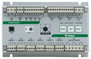
The PGR-8800 Arc-Flash Relay is a high-speed, arc-detection device for electrical powerdistribution systems. The PGR-8800 has one local sensor and supports both point and fiber-optic sensor technologies for optical arc detection. There are inputs for six optical sensors and three current sensors.
On the occurrence of an arc fault, the PGR-8800 detects the fault and pulses the trip contact in less than one millisecond. The tripping pulse is typically used to trip the circuit breaker(s) supplying the circuit. The total arcing time is effectively reduced to the mechanical opening time of the circuit breaker; typically between 30 and 75 milliseconds. The trip contact is a solid-state switch (IGBT), which provides fast reaction and sufficient drive capability for circuit-breaker trip circuits.
Using optical sensors rather than relying strictly on current measurement allows a much faster detection time than overcurrent relays or a circuit breaker alone can typically provide. This will lower the incident energy of an arc flash and increase worker safety, reduce fault damage, and improve uptime. Since the incident energy is decreased, the hazard risk category (HRC) and associated level of personal protective equipment (PPE) may also be lowered, subject to an arcflash study modeling the system parameters.
The MODBUS RTU protocol is implemented in the PGR-8800. This will provide status information for sensors, analog inputs, digital inputs, digital outputs, and numerous event and error flags. It also provides the ability to remotely reset the PGR-8800. See Section 11.3 and Appendices A and B.
The PGR-8800 can be used on any electrical system with any voltage (ac or dc) and can be powered from either an ac or dc supply, or both. If it is powered from line supply, it can charge a backup battery to power the PGR-8800 when the line supply is lost.
## _**1.1 Current-Supervised Arc-Flash Protection**_
The PGR-8800 has three phase-current inputs which can be used to prevent optical trips when the measured current is below a user-specified level. This makes it possible to avoid nuisance tripping from external light sources such as lightning or welding arcs.
## _**1.2 Definite-Time Overcurrent Protection**_
Using the phase-current inputs, the PGR-8800 can be configured to trip on overcurrent, with a minimum reaction time of one millisecond. There are two user-adjustable levels of overcurrent protection with independent trip times to coordinate with other protective devices. This provides protection from long-lasting overload conditions and fast reaction to overcurrent even when no arc is detected.
## _**1.3 Fail-Safe Operation**_
The PGR-8800 continuously monitors its internal circuitry as well as the connected optical sensors. Any system faults, including a sensor-cable fault, are indicated by a flashing LED and can be logged. A redundant trip circuit ensures that the PGR-8800 will trip on an arc flash even if a primary trip-circuit component fails. The solid-state design of the redundant trip circuit also provides a significantly faster response to an arc on power-up (for example, after maintenance during a shutdown) than is possible with microprocessor-only relays.
## _**1.4 Fast-Fault Location**_
The optical sensors used with the PGR-8800 include LED indication of health and, if it has detected an arc flash, of fault location. The PGR-8800 also has one LED per optical sensor to indicate which sensor(s) have caused a trip.
www.littelfuse.com
• © _2015_ Littelfuse •
• 7/86
_PGR-8800 Arc-Flash Relay_
_Rev. 3-B-092215_
## P/4 Littelfuse
## _**1.5 USB Interface**_
A USB interface on the front of the PGR-8800 provides easy PC access to configuration settings and access to an event log which provides detailed diagnostic information about measurements before and after a trip. No PC driver or software installation is required.
## _**1.6 Scalable System**_
Up to four PGR-8800 modules can be connected into a single system, allowing a total of 24 optical sensors per system.
## _**1.7 Upstream Circuit Breaker Tripping**_
The PGR-8800 can be configured to trip an upstream circuit breaker as a backup to local circuitbreaker failure. Circuit-breaker failure can be detected with a discrete input (such as a local circuit breaker feedback signal), current measurement, or the Link function. See Appendix C for more information.
www.littelfuse.com
• © _2015_ Littelfuse •
• 8/86
He Littelfuse
_PGR-8800 Arc-Flash Relay_
_Rev. 3-B-092215_
## _**2 INSTALLATION**_
The PGR-8800 can be surface mounted using four 5-mm (10-32) screws, or it can be DIN-rail mounted using the optional mounting brackets (PGA-0031).
Ensure there is enough clearance around the module to allow the plug-in terminals to be removed and inserted.
Do not install modules which have been damaged in transport.
See the PGR-8800 Arc-Flash Relay Application Guide for additional installation information.
**==> picture [398 x 359] intentionally omitted <==**
**----- Start of picture text -----**<br>
NOTES:<br>1. DIMENSIONS IN MILLIMETRES (INCHES).<br>2. MINIMUM CLEARANCE REQUIRED FOR CONNECTOR I. AABER RRRRRR ~=ERRRR RRR A<br> INSERTION AND REMOVAL. | i<br>3. CERTIFICATIONS NOT SHOWN. TOP<br>200.0<br>54.3 (7.88)<br>(2.14) 20.0 160.0 20.0<br>38.8 (0.79) (6.30) (0.79)<br>(1.53) Ny, kiz<br>@ lees2 el ecc l eceeeeeee| leea000000 000/ao ol 0@<br>wo" O tay * yar at is LA} iti let: t LI<br>° © 0000 ° @ ) °<br>ARC-FLASH RELAY PGR-8800 SERIES<br>5<br>[ ee t KR,<br>use LOCAL ‘TRIP LEVEL<br>° ° ° ° ©) ° °<br>@lcocclocco|ococlococloocc|oooessee a a jocoooe| |@<br>SIDE 4 OPEN SLOTS FRONT<br>5.6 X 6.8 (0.22 x 0.27)<br>200.0 NOTE 2<br>(7.88)<br>Pop 20.0 160.0 ” 20.0<br>(0.79) (6.30) (0.79)<br>6.0<br>(0.24)<br>—_I —<br>HERBIERa |BIRRee B ee EB B E<br>,— Ee<br>NOTE 2<br>MOUNTING DETAIL BOTTOM<br>4.0 (0.16)<br>122.2 (4.81) 130.2 (5.13)<br>0<br>4. (0.16)<br>10.0 (0.39)<br>5.0 (0.20)<br>130.0 (5.13)<br>10.0 (0.39)<br>**----- End of picture text -----**<br>
FIGURE 1. PGR-8800 Outline and Mounting Details.
www.littelfuse.com
• © _2015_ Littelfuse •
• 9/86
_PGR-8800 Arc-Flash Relay_
_Rev. 3-B-092215_
**==> picture [426 x 533] intentionally omitted <==**
**----- Start of picture text -----**<br>
LINK OR MODBUS CONNECTION (OPTIONAL) UP TO 4<br>+ PGR-8800 MODULES<br>CAN BE CONNECTED. SEE<br>- SECTION 11.<br>A B C<br>ALARM ONLINE TRIP<br>OPTIONAL R G R<br>24 VDC BATTERY<br>SEE SECTION 3 RESET Oo COILTRIP oe 4--h--<br>@ [5|4 dJ odd| [ ddo00000d) [Sddo0000 0d0q|Ld6 d 0l<br>WP ov er<br>LINE POWER eLINK INHIBITsrietTRIP RESET re Dewitt?ON LINE SERVICE TRIPPED TRIPLICOIL<br>{o) [o) 0 @e@ @ co) e e 2)<br>ARC-FLASH RELAY PGR-8800 SERIES<br>5<br>NOTE 4 aay 3 7<br>a | ro) ® oe woe Trip | | RESET<br>us LOCAL TRIP LEVEL 04 Littelfuse<br>SENSOR{o) 1 SENSOR(9) 2 SENSOR12) 3 SENSOR(2) 4 SENSOR(e) 5 SENSOR(2) 6 CURRENTio)SENSORS<br>PERE1°23 4 5ELE6 7 S8 9EERE10 11 12 ELE13 14 15 16S 17°EL18 «19ES200 21FERS22 23 24 25em26 27pm28 29em30<br>bad esck ed RSee COee 1 ee x SZ x Aeee eee) eee e OPTIONAL<br>5-A-SECONDARY<br>PHASE CT’S<br>NOTE 3<br>q co FES TB<br>A D cp| | a: |_|<br>TRANSMITTER RECEIVER<br>PGA-LS20 / PGA-LS30<br>f o FIBER OPTIC SENSOR M E sarren UME<br>PGA-LS10<br>POINT SENSOR<br>NOTES:<br>1. RELAY OUTPUTS SHOWN DE-ENERGIZED.<br>2. CURRENT SENSOR INPUTS MUST BE CONFIGURED. SEE SECTION 12.<br>3. A TOTAL OF SIX POINT OR FIBER-OPTIC SENSORS CAN BE CONNECTED.<br>4. USB ‘B’ CONNECTOR. FOR CONFIGURATION, SEE SECTION 12.<br>RED WHITE YELLOW SHIELD / BLACK RED WHITE SHIELD / BLACK RED YELLOW WHITE SHIELD / BLACK<br>**----- End of picture text -----**<br>
FIGURE 2. PGR-8800 Typical Wiring Diagram.
www.littelfuse.com
• © _2015_ Littelfuse •
• 10/86
_PGR-8800 Arc-Flash Relay_
_Rev. 3-B-092215_
**==> picture [426 x 534] intentionally omitted <==**
**----- Start of picture text -----**<br>
LINK OR MODBUS CONNECTION (OPTIONAL)<br>+ UP TO 4<br>PGR-8800 MODULES<br>- CAN BE CONNECTED. SEE SECTION 11. A B C<br>+24 VDC<br>0 V<br>ALARM ONLINE TRIP<br>R G R<br>TRIP<br>RESET 10) COIL<br>@ lo|2 d[ ded| [ dd0000008) [Sdd00000 00q|Ld6 d 0l<br>WP ov er<br>LINE POWER eLINK INHIBITsrietTRIP RESET re Dewitt?ON LINE SERVICE TRIPPED TRIPLICOIL<br>{o) [o) 0 @e@ @ co) e e 2)<br>ARC-FLASH RELAY PGR-8800 SERIES<br>5<br>NOTE 4 aay 3 7<br>a | ro) ® Trip | | RESET<br>us LOCAL TRIP LEVEL 04 Littelfuse<br>SENSOR{o) 1 SENSOR(9) 2 SENSOR12) 3 SENSOR(2) 4 SENSOR(e) 5 SENSOR(2) 6 CURRENTio)SENSORS<br>PERE1°23 4 5ELE6 7 S8 9EERE10 11 12 ELE13 14 15 16S 17°EL18 «19ES200 21FERS22 23 24 25em26 27pm28 29em30<br>x x<br>bad esck ed RSee COee 1 ee SZ Aeee eee) eee e OPTIONAL<br>5-A-SECONDARY<br>PHASE CT’S<br>NOTE 3<br><amp qt *<—_____} D y<br>cp =<br>TRANSMITTER RECEIVER<br>PGA-LS20 / PGA-LS30<br>f o M E sarren UME<br>FIBER OPTIC SENSOR<br>PGA-LS10<br>POINT SENSOR<br>NOTES:<br>1. RELAY OUTPUTS SHOWN DE-ENERGIZED.<br>2. CURRENT SENSOR INPUTS MUST BE CONFIGURED. SEE SECTION 12.<br>3. A TOTAL OF SIX POINT OR FIBER-OPTIC SENSORS CAN BE CONNECTED.<br>4. USB ‘B’ CONNECTOR. FOR CONFIGURATION, SEE SECTION 12.<br>RED WHITE YELLOW SHIELD / BLACK RED WHITE SHIELD / BLACK RED YELLOW WHITE SHIELD / BLACK<br>**----- End of picture text -----**<br>
FIGURE 3. PGR-8800 24-Vdc Source Typical Wiring Diagram.
www.littelfuse.com
• © _2015_ Littelfuse •
• 11/86
_PGR-8800 Arc-Flash Relay_
_Rev. 3-B-092215_
## ~~Puitteuse =~~ _**3 POWER SUPPLY**_
The PGR-8800 Arc-Flash Relay can be powered from an ac or dc supply, or both. However, only one source can be connected to terminals 31 and 32.
## _**3.1 AC Supply**_
Connect an ac supply to terminals 31 and 32. The supply voltage must be 100 to 240 Vac.
**==> picture [74 x 157] intentionally omitted <==**
**----- Start of picture text -----**<br>
100-240 VAC<br>N L GND<br>31 32 33<br>L2/ L1<br>N<br>LINE<br>**----- End of picture text -----**<br>
## _**3.2 DC Supply**_
Connect a dc supply to terminals 31 and 32, ensuring correct polarity. The supply voltage must be 110 to 250 Vdc.
**==> picture [75 x 139] intentionally omitted <==**
**----- Start of picture text -----**<br>
110-250 VDC<br>- + GND<br>31 32 33<br>L2/ L1<br>N<br>LINE<br>**----- End of picture text -----**<br>
www.littelfuse.com
• © _2015_ Littelfuse •
• 12/86
P/4 Littelfuse
_PGR-8800 Arc-Flash Relay_
_Rev. 3-B-092215_
## _**3.3 Low-Voltage DC Supply**_
Connect a dc supply to terminals 34 and 36, ensuring correct polarity. The supply voltage must be 14 to 48 Vdc. This input will not charge the backup battery.
**==> picture [38 x 120] intentionally omitted <==**
**----- Start of picture text -----**<br>
14-48 VDC<br>+ -<br>—_— 34 35 36<br>+ B 0<br>V A V<br>T<br>POWER<br>**----- End of picture text -----**<br>
## _**3.4 External 24-V Battery Backup**_
Connect a 24-Vdc battery to terminals 35 and 36, ensuring correct polarity. The PGR-8800 will only charge the battery when there is rated voltage on power-supply terminals 31 and 32 (ac or dc). The PGR-8800 supplies a constant-current, constant-voltage (CCCV) of 27 V with no load and maximum available current of 200 mA. A sealed lead-acid battery with a capacity between 2 and 15 Ah, such as a pair of Panasonic VRLA LC-R122R2P, should be used and exchanged regularly according to the manufacturer’s recommendations.
If the PGR-8800 is supplied by the backup battery and the battery voltage drops below 20 V, the PGR-8800 will shut down to protect the battery.
Do not combine external battery backup and the low-voltage DC supply. The DC supply will not charge the battery.
~~Ce~~ **NOTE:** Arc monitoring is disabled when the PGR-8800 is powered down.
**==> picture [34 x 24] intentionally omitted <==**
**----- Start of picture text -----**<br>
24 VDC<br>BATTERY<br>+ -<br>**----- End of picture text -----**<br>
**==> picture [34 x 30] intentionally omitted <==**
**----- Start of picture text -----**<br>
34 35 36<br>+ B 0<br>V A V<br>T<br>POWER<br>**----- End of picture text -----**<br>
www.littelfuse.com
• © _2015_ Littelfuse •
• 13/86
_PGR-8800 Arc-Flash Relay_
_Rev. 3-B-092215_
## P/4 Littelfuse
## _**4 OPTICAL SENSORS**_
The PGR-8800 has one local sensor and six inputs for external optical sensors. The local sensor is primarily used for commissioning and can also be enabled for arc-flash protection. Its lightdetection zone is illustrated in the diagram below.
**==> picture [159 x 156] intentionally omitted <==**
**----- Start of picture text -----**<br>
1 m<br>(3.3 ft) ARC-FLASH RELAY PGR-8800 SERIES<br>2 m<br>(6.6 ft)<br>150°<br>70°<br>' \<br>**----- End of picture text -----**<br>
FIGURE 4. Local Sensor Detection Zone for a 3 kA Fault.
Two external sensor types are supported:
- PGA-LS10 Photoelectric Point Sensors with sensor check
- PGA-LS20 and PGA-LS30 Fiber-Optic Sensors with sensor check
The sensors can be used together, in any combination.
Both sensor types have LED indication of sensor health and fault location. A sensor-check circuit tests the sensor to verify that the sensor assembly is functioning correctly. A healthy sensor will indicate two fast flashes of its internal red LED every few seconds. A sensor that has detected an arc will slowly flash red.
The sensors connect to the PGR-8800 with shielded three-wire 20 AWG (0.5 mm[2] ) electrical cable. Each sensor includes 10 m (33 ft) of cable which can be shortened or extended up to 50 m (164 ft). These cables should be considered to be at ground potential when determining electrical clearances in the cabinet.
Any connected optical sensor with circuit check will be automatically detected and cause the PGR-8800 to report an error if it is subsequently disconnected.
**PGA-LS10**
**PGA-LS20 / PGA-LS30**
**NOTE:** Inserting and removing sensor cables can cause a trip depending on which terminals make contact first. Always place the unit in service mode before connecting and disconnecting sensors.
www.littelfuse.com
• © _2015_ Littelfuse •
• 14/86
P/4 Littelfuse
_PGR-8800 Arc-Flash Relay_
_Rev. 3-B-092215_
## _**4.1 PGA-LS10 Photoelectric Point Sensor with Sensor Check**_
This sensor has a detection area of a 2-m (7 ft) half-sphere for arcs of 3 kA or more.
A built-in LED enables the PGR-8800 to verify the function of the light sensor, wiring, and electronics. If the sensor does not detect the sensor-check LED, a sensor-fail alarm will occur -- the ONLINE output will change state and the ONLINE LED will begin to short flash. See Section 9.
The sensor includes 10 m (33 ft) of shielded three-wire electrical cable which can easily be shortened or extended to a maximum of 50 m (164 ft). Use Belden 85240 or equivalent cable (wire colors may vary).
**==> picture [403 x 261] intentionally omitted <==**
**----- Start of picture text -----**<br>
3 kA<br>2 m (6.6 ft)<br>2 m (6.6 ft)<br>PGA-LS10<br>2 m (6.6 ft)<br>2 m (6.6 ft)<br>2.5 m (8.2 ft)<br>**----- End of picture text -----**<br>
FIGURE 5. PGA-LS10 Detection Range for a 3 kA Fault.
www.littelfuse.com
• © _2015_ Littelfuse •
• 15/86
_PGR-8800 Arc-Flash Relay_
_Rev. 3-B-092215_
## P/4 Littelfuse
## _**4.1.1 PGA-LS10 Connection**_
**==> picture [391 x 505] intentionally omitted <==**
**----- Start of picture text -----**<br>
9.6<br>(0.38)<br>|<br>14.2<br>J @\o 2 elo c cloeeeeceea | looeccece<br>al (0.56) = a | | e<br>ARC-FLASH RELAY<br>L<br>2.4<br>(0.09) 23.8<br>— _ () 7<br>(0.94)<br>_<br>POINT SENSOR SIDE VIEW<br>a | | ee| | |<br>@ \cogclecceleccoloceojococeooe<br>Ø4.25(0.167)<br>MOUNTING HOLES<br>, NOTE 2<br>Ø8.3(0.33)<br>SENSOR LENS<br>RED LED FOR<br>QOI CIRCUIT CHECK AND y3<br>VISUAL DIAGNOSTICS<br>(0.16)4.0 -#——____+ (0.94)24.0 2| L f o) e<br>32.0 NOTES<br>(1.26)<br>1. DIMENSIONS IN MILLIMETERS (INCHES) UNLESS OTHERWISE STATED.<br>POINT SENSOR TOP VIEW<br>2. UP TO 6 PGA-LS10 PHOTOELECTRIC POINT SENSORS WITH BUILT-IN<br>CIRCUIT CHECK CAN BE CONNECTED.<br>3. THE PGA-LS10 SENSOR SHIPS ASSEMBLED WITH A PLUG-IN CONNECTOR.<br>IT MAY BE NECESSARY TO DISCONNECT THE PLUG-IN CONNECTOR<br>DURING INSTALLATION.<br>TERMINAL FUNCTION COLOR<br>5V SUPPLY RED<br>TX CIRCUIT CHECK TRANSMIT WHITE<br>RX RECEIVE YELLOW<br>0V SHIELD BLACK/COPPER<br>8.3<br>(0.33)<br>RED WHITE YELLOW SHIELD / BLACK<br>10 m<br>(32.8 ft)<br>RED WHITE YELLOW SHIELD / BLACK<br>52.0 (2.05) 44.0 (1.73)<br>**----- End of picture text -----**<br>
FIGURE 6. PGA-LS10 Connection Diagram.
www.littelfuse.com
• © _2015_ Littelfuse •
• 16/86
_PGR-8800 Arc-Flash Relay_
_Rev. 3-B-092215_
## P/4 Littelfuse
## _**4.1.2 PGA-LS10 Installation**_
Point sensors include an adhesive-backed drill template for easy surface or panel-mount installation.
**==> picture [370 x 319] intentionally omitted <==**
**----- Start of picture text -----**<br>
PANEL SURFACE<br>NOTE 3<br>PANEL<br>= Ø9(0.354) o ve<br>PGA-LS10<br>DRILL TEMPLATE<br>SURFACE PANEL<br>SURFACE<br>Ø9(0.354)<br>DRILL TEMPLATE SURFACE-MOUNTED PANEL-MOUNTED<br>PGA-LS10 PGA-LS10<br>NOTES AND INSTALLATION:<br>1. ALL DIMENSIONS IN MILLIMETERS (INCHES).<br>2. AFFIX THE DRILL TEMPLATE WHERE THE SENSOR IS TO BE<br> MOUNTED.<br>3. MOUNTING SCREWS ARE M4 OR 8-32.<br>4. THE PGA-LS10 CAN BE SURFACE OR PANEL MOUNTED. SELECT<br> THE APPROPRIATE HOLES AND DRILL THROUGH THE TEMPLATE.<br>**----- End of picture text -----**<br>
FIGURE 7. PGA-LS10 Mounting Detail.
www.littelfuse.com
• © _2015_ Littelfuse •
• 17/86
P/4 Littelfuse
_PGR-8800 Arc-Flash Relay_
_Rev. 3-B-092215_
## _**4.2 PGA-LS20 and PGA-LS30 Fiber-Optic Sensors with Sensor Check**_
The PGA-LS20 and PGA-LS30 have a 360° detection zone along the fiber’s length. A built-in LED enables the PGR-8800 to verify the function of the light sensor, wiring, and electronics. If the sensor does not detect the sensor-check LED, a sensor-fail alarm will occur -- the ONLINE output will change state and the ONLINE LED will begin to short flash. See Section 9.
The PGA-LS20 and PGA-LS30 sensors have three components:
1. A fiber-optic cable, with one end covered with a black sleeve. The PGA-LS20 has 8 m (26 ft) of active fiber and 2 m (7 ft) of covered fiber. The PGA-LS30 has 18 m (59 ft) of active fiber and 2 m (7 ft) of covered fiber.
2. A transmitter with a white enclosure and a white thumb nut.
3. A receiver with a white enclosure, a black thumb nut, and an adjustment screw behind an access hole.
Both the receiver and the transmitter connect to one PGR-8800 input using shielded three-wire electrical cable. All three components are monitored to ensure correct operation.
## _**4.2.1 Fiber Connection**_
The fiber is the light-collecting element of the PGA-LS20 and PGA-LS30. It must be installed so it has line-of-sight to all current-carrying parts. In some cases this may be accomplished by following the bus bars along the back wall of the cabinets.
Drill holes using the included drill template and fasten the transmitter and receiver to the cabinet walls using rivets or screws. Connect the attached cables to the PGR-8800. The wires of the transmitter and receiver must be connected as shown in Fig. 8.
Connect the black-sleeve-covered end to the receiver using the black thumb nut, and the white uncovered end to the transmitter using the white thumb nut. Ensure the fiber is inserted completely into the transmitter and receiver and the nuts are tightened. Pull gently on the cable to verify a secure connection. The maximum pull strength of the fiber is 30 N (6.7 lbf).
The fiber should not be sharply bent or pinched. The minimum bending radius is 5 cm (2”). Ensure that any drilled holes are free of any sharp edges or burrs. Use grommets for further protection.
**NOTE:** Removing the fiber from the transmitter end only can cause a trip if the end of the fiber is pointed towards a light source, since the fiber conducts light. When servicing the arc flash relay, always place the unit in service mode before connecting and disconnecting sensors and fibers.
## _**4.2.2 Receiver Wiring Connections**_
Connect the red wire to 5V. Connect the yellow wire to RX. Connect the white wire **and** the shield to 0V.
## _**4.2.3 Transmitter Wiring Connections**_
Connect the red wire to 5V. Connect the white wire to TX. Connect the shield to 0V.
The yellow wire is not used.
www.littelfuse.com
• © _2015_ Littelfuse •
• 18/86
P/4 Littelfuse
_PGR-8800 Arc-Flash Relay_
_Rev. 3-B-092215_
## _**4.2.4 PGA-LS20 and PGA-LS30 Connection**_
The sensor is shipped with the wires mounted in a terminal block. See Fig 8.
The transmitter and receiver include 10 m (33 ft) of shielded three-wire electrical cable which can be shortened or extended up to 50 m (164 ft). Transmitter and receiver cables can be different lengths and must be independently shielded. Use Belden 85240 or equivalent cable (wire colors may vary). Failure to independently shield transmitter and receiver cables can lead to an incorrect circuit check – a faulty sensor could be falsely detected as continuous. However, if there is no sensor fault, arc-flash detection will function normally in this condition.
**==> picture [413 x 474] intentionally omitted <==**
**----- Start of picture text -----**<br>
2.0<br>(0.08) _<br>(oe) (oe)<br>SENSOR 1 SENSOR 2 i<br>Py a ;<br>18.8<br>(0.74)<br>i SS)<br>' : FIBER-OPTIC SENSOR SIDE VIEW<br>(oJ lo) [oJ lo 24.0<br>4.0<br>(0.94)<br>(0.16)<br>Ø4.25(0.167)<br>MOUNTING HOLES<br>4.0<br>(0.16)<br>UTE aren ULI BLACK<br>RECEIVER<br>(PGA-LS20: 8 m, 26.2 ft)FIBER ; BLACK SLEEVE(PGA-LS20: 2 m, 6.5 ft) SENSITIVITYADJUSTMENT<br>(PGA-LS30: 18 m, 59 ft) (PGA-LS30: 2 m, 6.5 ft) SCREW<br>DECREASE<br>NOTES SENSITIVITY<br>1. DIMENSIONS IN MILLIMETERS (INCHES) UNLESS OTHERWISE<br>STATED. THUMB NUT<br>2. UP TO 6 PGA-LS20 / PGA-LS30 FIBER-OPTIC SENSORS 32.0<br>WITH BUILT-IN CIRCUIT CHECK CAN BE CONNECTED. (1.26)<br>3. THE PGA-LS20 AND PGA-LS30 SENSORS SHIP FIBER - OPTIC SENSOR TOP VIEW<br>ASSEMBLED WITH A PLUG-IN CONNECTOR. IT MAY BE NECESSARY<br>TO DISCONNECT THE PLUG-IN CONNECTOR DURING INSTALLATION.<br>TERMINAL FUNCTION COLOR<br>5V SUPPLY (TRANSMITTER AND RED<br>RECEIVER)<br>TX SENSOR CHECK (TRANSMITTER) WHITE<br>RX SIGNAL (RECEIVER) YELLOW<br>0V SENSOR CHECK (RECEIVER) AND BLACK/COPPER<br>BOTH SHIELDS<br>46.0 (1.81)<br>RED WHITE SHIELD / BLACK RED WHITE YELLOW SHIELD / BLACK<br>46.0 (1.81) 42.0 (1.65)<br>**----- End of picture text -----**<br>
FIGURE 8. PGA-LS20 and PGA-LS30 Connection Diagram.
www.littelfuse.com
• © _2015_ Littelfuse •
• 19/86
_PGR-8800 Arc-Flash Relay Rev. 3-B-092215_ ~~Sie~~ _**5 SENSOR PLACEMENT**_
## _**5.1 General Guidelines**_
Optical sensors require line-of-sight to points being monitored. Ensure that the point sensors and fiber are not blocked by fixed or moveable objects. Areas that will be accessed for maintenance or with moveable parts (such as draw-out circuit breakers) should be considered a high priority for installation. Do not place sensors or cables on bare components that will be energized and avoid sharp bends in the cable, particularly when using the PGA-LS20 and PGA-LS30 fiber-optic sensors. The electrical cables and sensors should be considered to be at ground potential when determining electrical clearances.
Sensors should be mounted in a location that will minimize the chance of debris or dust build-up and with easy access for maintenance if needed. A point sensor mounted at the top of an enclosure and facing down is optimal for reducing dust build-up. It should be noted that most enclosures are metallic and the reflectivity combined with the high intensity of an arc mean that even a dirty sensor will collect adequate light.
Sensors can be tested individually by putting the PGR-8800 into service mode by pressing the MODE button and shining a bright light on the sensor. A trip will be indicated if the sensor detects the light, but a trip signal will not be sent to the circuit breaker. If the LED on the sensor or relay isn’t indicating a trip, cleaning is necessary. Note that in service mode, the PGR-8800 will not trip if an arc flash occurs. Remember to return the PGR-8800 to online mode after testing is completed. In dusty environments, sensor cleaning should be part of a regular maintenance schedule and can be performed using compressed air or a dry cloth.
## _**5.2 Switchgear Protection**_
The sensors used for arc-flash detection are optical sensors. Line-of-sight between the points where an arc could occur and the sensor is crucial.
Often one point sensor is sufficient to monitor a complete switchgear compartment. However, if there are large components such as circuit breakers that cast shadows over wider areas, more than one point sensor is required.
**==> picture [331 x 131] intentionally omitted <==**
**----- Start of picture text -----**<br>
ARC-FLASH RELAY PGR-8800 SERIES<br>SENSOR 5<br>SENSOR 4<br>bsse[savefsasefravefeavefsose] [overs ely SENSOR 3 WY SENSOR 2<br>SENSOR 1<br>BREAKERMAIN SHOWNDEVICES NOT<br>SHOWNDEVICES NOT<br>INCOMING SHOWNDEVICES NOT FIBER SENSORPGA-LS20<br> CURRENT (CT1,CT2,CT3) SENSORS<br>TRIP<br>PGA-LS10<br>POINT SENSOR<br>PGA-LS10<br>POINT SENSOR<br>PGA-LS10<br>POINT SENSOR<br>PGA-LS10<br>POINT SENSOR<br>**----- End of picture text -----**<br>
## _**5.3 Transformer Protection**_
The PGR-8800 can also be used for the protection of transformers. Two or more point sensors should be used per transformer to monitor the primary and secondary connection terminals. For the placement of the sensors, the same considerations apply as for switchgear protection.
www.littelfuse.com
• © _2015_ Littelfuse •
• 20/86
_PGR-8800 Arc-Flash Relay_
_Rev. 3-B-092215_
## P/4 Littelfuse
## _**6 CURRENT SENSORS**_
The PGR-8800 has three phase-current inputs which can be configured in a current-supervised trip inhibit mode and for overcurrent protection.
The current inhibit mode prevents the module from tripping on a light signal, unless the current is above a threshold. This can prevent nuisance tripping e.g. photo flashes or welding in the area.
The overcurrent protection provides a fast, but less accurate ANSI 50 overcurrent protection function.
The current-sensor inputs can also be used to verify that the local circuit breaker has tripped successfully, providing an ANSI 50BF circuit breaker failure function. See Appendix C for more information.
## _**6.1 Current Inhibit Mode**_
If the current-supervised trip inhibit mode is enabled, the PGR-8800 will only trip when the following conditions apply:
- An arc is detected by an optical sensor, and
- Current detected by a current sensor exceeds the inhibit threshold.
The PGR-8800 will trip after the programmed delay time for the light as soon as the absolute value of the current on any phase exceeds the inhibit setting. Thus, the current inhibit does not add any delay to the trip if the arc is drawing current.
## _**6.2 Overcurrent Protection**_
In addition, two definite-time overcurrent protection levels are provided that will trip on current detection alone. Overcurrent levels can be set from 150 to 1,000% of rated nominal load current. Overcurrent protection is not active by default, and must be set using the configuration software.
Overcurrent trip times can be set between 1 and 20,000 milliseconds. The trip decision is based on an internal counter. The PGR-8800 will increment the counter if a sample exceeds the trip-level setting and decrement it when a sample is below the setting. When the counter exceeds the number of samples necessary to exceed the time delay, the PGR-8800 will trip. The time for the trip coil IGBT (insulated-gate bipolar transistor) to operate is approximately 0.2 milliseconds, which happens after the time delay.
**NOTE:** Using overcurrent trip on a system with fewer than three phase current sensors can significantly increase trip times and levels. This does not apply to the inhibit system, which will function at no added delay, also in single phase systems.
www.littelfuse.com
• © _2015_ Littelfuse •
• 21/86
_PGR-8800 Arc-Flash Relay_
_Rev. 3-B-092215_
## P/4[Littelfuse] a
## _**6.3 Current Sensor Characteristics**_
The current-sensor inputs require 5-A-secondary current sensors. Three phase-current sensors are required for optimal performance. For best performance, select current sensors with a primary rating approximately equal to the system’s rated current and protection class 10P5 or better. The current sensors can be placed in series with other equipment as long as the total burden of the wiring and inputs are within the current sensor rating.
The PGR-8800 measures instantaneous currents and is insensitive to phasing and polarity. The current-sensor inputs have a burden of less than 0.25 VA at 5 A, will withstand up to 75 A for one second, and are isolated from all other terminals up to 500 Vac.
**==> picture [299 x 185] intentionally omitted <==**
**----- Start of picture text -----**<br>
CURRENT SENSORS Ø A Ø B Ø C<br>ey ea ey<br>25 26 27 28 29 30<br>e e<br>= 5A SECONDARY CT’S REQUIRED<br>OPTIONAL 3-PHASE<br>OVERCURRENT PROTECTION<br>**----- End of picture text -----**<br>
www.littelfuse.com
• © _2015_ Littelfuse •
• 22/86
P/4 Littelfuse
_PGR-8800 Arc-Flash Relay_
_Rev. 3-B-092215_
## _**7 DIGITAL INPUTS**_
The PGR-8800 has three digital-input functions; trip inhibit, trip and reset. Each function has two inputs to simplify wiring.
By default, the inputs are considered active when connected to COM (terminal 45). The inputs can also be configured to be active when not connected to terminal 45 and to use circuit check in the configuration software. See Section 12.2.7.
## _**7.1 Inhibit**_
The INHIBIT function suppresses a trip signal.
There are two INHIBIT inputs: terminals 39 and 40.
When inhibit is activated, the PGR-8800 will indicate that an arc fault is being detected, but will not pulse the trip-coil output. If the PGR-8800 detects an arc fault while inhibited, the sensor LED and INHIBIT LED will flash.
Inhibit can also block a digital-input if so configured. See Section 12.2.7. The INHIBIT input is enabled by default.
**==> picture [74 x 25] intentionally omitted <==**
**----- Start of picture text -----**<br>
INHIBIT INHIBIT TRIP TRIP RESET RESET<br>**----- End of picture text -----**<br>
## _**7.2 Trip**_
The TRIP input is used to remotely trip the PGR-8800. Once activated, the PGR-8800 will pulse the TRIP COIL output instantaneously.
There are two TRIP inputs: terminals 41 and 42.
In SERVICE mode, this input does not affect the TRIP COIL output.
The TRIP input can also be configured to connect to the auxiliary contact of a circuit breaker to verify that the circuit breaker has tripped successfully. See Appendix C.
The TRIP input is enabled by default.
## _**7.3 Reset**_
The RESET input is used as a remote reset after a fault has been detected.
There are two RESET inputs: terminals 43 and 44.
Activating this input will reset an alarm or error, clear the TRIPPED and TRIP COIL outputs, clear the indicators, and place the unit back in service or online mode, depending on the mode it was operating in prior to the trip.
If the reset input is permanently connected to COM, the PGR-8800 will auto reset after a trip has occurred. The reset input is enabled by default.
TO TERMINAL 45, COM CABLE-MONITORING 82 kΩ RESISTOR
## _**7.4 Circuit Check**_
A circuit-check feature can be enabled for each digital input in the configuration software. This feature will cause the module to report an error if the connection to the digital input is open or broken. Circuit check requires an 82 kΩ resistor connected in parallel with the external contact. This resistor must be connected as close as possible to the contact to ensure the full-length of the cable is protected.
www.littelfuse.com
• © _2015_ Littelfuse •
• 23/86
_PGR-8800 Arc-Flash Relay_
_Rev. 3-B-092215_
## P/4 Littelfuse
## _**8 OUTPUTS**_
An LED provides visual indication of each output status. The output contacts are shown on the faceplate in the powered-off state.
## _**8.1 Online**_
The ONLINE output consists of two contact sets:
- A change-over (Form C) contact (terminals 46-48)
- A normally-open status contact, STO (terminal 49) with reference to COM (terminal 45)
The ONLINE output is energized unless the PGR-8800:
-
- detects an optical sensor fault,
- detects a cable fault on a digital input if cable monitoring is activated in the configuration software,
- detects loss of trip coil supply voltage,
- loses supply voltage, or
- is in service mode
## _**8.2 Service**_
The SERVICE output consists of two contact sets:
- A change-over (Form C) contact (terminals 50-52)
- A normally-open status contact STS (terminal 53) with reference to COM (terminal 45)
The SERVICE output signals that the PGR-8800 is being commissioned or set up. The output is energized when the PGR-8800:
- is in service mode, or
- is connected via USB to a PC
The SERVICE output can also be configured to trip an upstream device after a local circuit-breaker failure or to follow the Trip Coil output. See Appendix C.
## _**8.3 Tripped**_
The TRIPPED output consists of two contact sets:
- A change-over (Form C) contact (terminals 54-56)
- A normally-open status contact STT (terminal 57) with reference to COM (terminal 45)
**NOTE:** The TRIPPED output is used for signalling a trip condition to a remote monitoring system or to trip an upstream circuit breaker. It is not intended to trip the local circuit breaker due to the ~~ee~~ slower response time of a mechanical relay. In default configuration, the TRIPPED output will energize if the PGR-8800 detects a fault during regular operation or in service mode.
The TRIPPED output can also be configured to trip an upstream device (with a delay of approximately five milliseconds) after a local circuit-breaker failure, or to follow the TRIP COIL output. See Appendix C.
www.littelfuse.com
• © _2015_ Littelfuse •
• 24/86
P/4 Littelfuse
_PGR-8800 Arc-Flash Relay_
_Rev. 3-B-092215_
## _**8.4 Trip Coil**_
Use the TRIP COIL output to trip a shunt or undervoltage circuit breaker. The operating mode is programmable using the PGR-8800 configuration software. See Section 12.2.8.
The TRIP COIL output can be used for trip coils with a 24 to 300 Vac/Vdc supply voltage. The output is monitored to verify that there is voltage available to the tripping circuit. If voltage is not detected, the ONLINE output will change state and its LED will flash green.
The TRIP COIL output is a pulsed output when in shunt trip mode. When an arc flash is detected, the TRIP COIL output is activated in less than one millisecond. When overcurrent protection is enabled and an overcurrent is detected, the TRIP COIL output is activated after an adjustable delay. The TRIP COIL output is deactivated after the adjustable pulse period delay. The output is an IGBT that can carry 10 A ac or dc for five seconds.
The TRIP COIL output is isolated up to 1,000 Vac.
**NOTE:** The TRIP COIL output is an IGBT switch. There is a voltage drop of 2-4 V across the ~~Ps~~ TRIP COIL output when energized. See Section 14. The TRIP COIL output consists of a rectifier bridge and an IGBT. The IGBT is able to switch large currents and high voltages. In combination, this creates a very fast relay-like switch which is able to trip even large circuit breakers without the added delay of a mechanical relay.
**NOTE:** The TRIP COIL output functions as a momentary switch and is protected against thermal overload. It will gradually lower the time the trip coil is active if the PGR-8800 is tripped repeatedly.
By default, when the PGR-8800 is in service mode, the TRIP COIL output will not operate when an arc-flash or overcurrent trip occurs, but it will operate when the TRIP button is pressed for at least one second. The TRIP COIL output can also be programmed to trip while in service mode using the configuration software.
**==> picture [82 x 79] intentionally omitted <==**
**----- Start of picture text -----**<br>
0 A<br>a<br>0 B<br>0 C<br>TRIP VOLTAGE<br>24-300 VAC / VDC<br>**----- End of picture text -----**<br>
www.littelfuse.com
• © _2015_ Littelfuse •
• 25/86
_PGR-8800 Arc-Flash Relay_
_Rev. 3-B-092215_
## P/4 Littelfuse
## _**9 LED INDICATION**_
**==> picture [471 x 193] intentionally omitted <==**
**----- Start of picture text -----**<br>
FAST FLASHING<br>LINE<br>On, green Supply voltage is connected ON<br>Off Supply voltage is not connected OFF noon. 100 ms 200 ms 1 s<br>POWER<br>SLOW FLASHING<br>On, green PGR-8800 is running from a<br>supply other than battery ON<br>Slow green flashing PGR-8800 is running from the OFF Coo<br>Battery input. The PGR-8800 400 ms 800 ms 1200 ms<br>will shut down at 20 V to protect<br>the battery from damage SHORT FLASHING<br>Short green flashing PGR-8800 is charging a battery ON<br>1500 ms<br>Off PGR-8800 is not powered OFF ————ie 100 ms 1600 ms 2 s<br>**----- End of picture text -----**<br>
## **LINE**
On, green Supply voltage is connected
Off Supply voltage is not connected
## **POWER**
On, green PGR-8800 is running from a supply other than battery
**LINK** FIGURE 9. LED Flash Patterns.
- On, green Link mode is enabled and active
Green flashing (intermittent)
Network traffic indication
Slow red flashing A relay in the system is tripping. If the trip is locally inhibited, the Link LED will revert to green when the trip source is removed
Short red flashing Link mode is enabled but not all relays are being detected Off Link mode is disabled
## **INHIBIT**
On, red INHIBIT input is active or current sensing is inhibiting trips (current not above setting)
Fast red flashing The PGR-8800 detects an arc (light), but the INHIBIT input or current sensing is preventing a trip
Short red flashing Digital-input circuit check failed; check the wiring of the inputs, or use the configuration software to disable circuit check
Off INHIBIT input is inactive
## **TRIP**
On, red TRIP input or another trip source is active
Fast red flashing TRIP input is causing a trip Slow red flashing Last trip was caused by this input or by the TRIP button on the front panel. Press RESET in Online mode to clear the trip
Short red flashing Digital-input circuit check failed; check the wiring of the inputs, or use the configuration software to disable circuit check
Off
TRIP input is inactive
www.littelfuse.com
• © _2015_ Littelfuse •
• 26/86
_PGR-8800 Arc-Flash Relay_
_Rev. 3-B-092215_
## P/4 Littelfuse
## **RESET**
On, red RESET input or another reset source is active Short red flashing Digital-input circuit check failed; check the wiring of the inputs, or use the configuration software to disable circuit check Off RESET input is inactive
## **ONLINE**
On, green PGR-8800 is online, active and operational; the TRIP COIL output will pulse if trip conditions are met Short green flashing PGR-8800 has detected an error. The front-panel LED’s will provide error information. The TRIP COIL output will still operate if trip conditions are met Off PGR-8800 is off or in service mode
## **SERVICE**
On, red PGR-8800 is in service mode. Please note it will switch to and stay in service mode if a USB cable and PC are connected. In service mode, the TRIP COIL output can be activated from the front-panel TRIP button but not by an arc fault, overcurrent, or TRIP input, unless configured to trip in service mode. See Section 12.2.8.
Press and hold RESET to configure the sensors. See Section 13.1.
Short red flashing PGR-8800 is in service mode, and has detected an error. The front-panel LED’s will provide error information Slow red flashing PGR-8800 is in the process of auto set up or firmware update Off PGR-8800 is off or in online mode **TRIPPED** On, red The TRIP COIL output is or has been active or was prevented from activating while in service mode. Press RESET to clear the trip Off No unacknowledged trips
## **TRIP COIL**
On, green TRIP COIL output is ready and detects trip voltage of 5 V or more in shunt mode
Fast red flashing TRIP COIL output is activated due to an existing trip event and is currently pulsing the output Slow red flashing TRIP COIL output has been activated and has completed the pulsed output. Press RESET to clear the trip Short red flashing TRIP COIL output is blocking less than 5 V. The trip voltage is missing; check the wiring and the power supply to the trip coil
www.littelfuse.com
• © _2015_ Littelfuse •
• 27/86
_PGR-8800 Arc-Flash Relay_
_Rev. 3-B-092215_
## P/4 Littelfuse
## **LOCAL**
On, green
Online mode. The front-panel sensor is configured for use as a trip sensor
The LED may also indicate that the PGR-8800 is powering up if it is the only lit LED. If this condition remains for an extended period, it indicates unit error
- Slow green flashing If the SERVICE LED is also flashing, the PGR-8800 is awaiting manual confirmation of the connected sensors. See Section 13.1
- Fast green flashing The internal supervisor or a USB host is reading or writing to internal memory, or the light detected on the front sensor is close to trip level
## **SENSORS**
- On, green SENSOR input is active and has a connected sensor
- Fast green flashing Sensor is currently detecting more than 50% of the light level needed to trip. The level at which this occurs is programmable. This is a warning only. If this warning is active during normal condition, it may indicate that the system Trip Level is set too low, which could lead to unintentional tripping
- Slow red flashing Sensor caused a trip event. Press RESET to clear the trip
- Short red flashing Sensor check of the sensor failed; check the wiring and, if using a PGA-LS20 or PGA-LS30 ensure the small metal adjustment screw is not set to minimum sensitivity. See Section 13.
Off SENSOR input is inactive
## **CURRENT SENSORS**
- On, green Current sensors are activated and configured
- On, red Current is above the inhibit level
- Fast green flashing Current sensors are detecting more than 50% of the current level needed to trip. The level at which this occurs is programmable. This is a warning only. If this warning is active during normal condition, it may indicate that the system Trip Level is set too low, which could lead to unintentional tripping
- Fast red flashing Current sensor is causing a trip event
- Slow red flashing The PGR-8800 has tripped on overcurrent. Press RESET in online mode to clear the trip
Off Current sensors are inactive
## **PGA LS10, PGA-LS20, PGA-LS30**
- Short red flashing Sensor is operating normally. Double flashes occur every few seconds
- Slow red flashing Sensor has detected an arc
- Off Sensor inactive
www.littelfuse.com
• © _2015_ Littelfuse •
• 28/86
_PGR-8800 Arc-Flash Relay_
_Rev. 3-B-092215_
## P/4 Littelfuse
## _**10 PGR-8800 BUTTONS**_
## _**10.1 Mode**_
The MODE button switches the PGR-8800 between online and service mode.
## _**10.2 Trip**_
In service mode, when the TRIP button is pressed for more than one second, the TRIP COIL output is activated. In online mode, the TRIP button is disabled.
## _**10.3 Reset**_
In online mode, press the RESET button to clear a trip (if trip conditions are no longer present). In service mode, when the RESET button is pressed for more than one second, the optical sensor detection process will begin. See Section 13.1.
## _**10.4 Mode + Reset**_
When MODE and RESET are pressed for more than 20 seconds, a file system reset will occur. This will erase the logged information.
## _**10.5 Mode + Trip**_
When MODE and TRIP are pressed for more than 20 seconds, a reset of all configuration settings to factory defaults will occur. This will not clear the logged information on the file system.
www.littelfuse.com
• © _2015_ Littelfuse •
• 29/86
_PGR-8800 Arc-Flash Relay_
_Rev. 3-B-092215_
## P/4 Littelfuse
## _**11 LINK**_
The PGR-8800 Link function allows up to four PGR-8800 modules to be connected to form a single system. This enables the PGR-8800 to share sensor inputs and relay outputs as if they were one unit. The maximum link cable length is 10 m (33 ft).
It is necessary to configure the Link function before use. See Section 12.2.9.
## _**11.1 Configuration**_
Set the Link interface, address, and number of connected modules with the configuration software.
Each PGR-8800 must have a unique link address, starting from one for the module connected to the local circuit breaker.
The PGR-8800 Link function continuously monitors link-cable-break faults.
## _**11.2 Button Function**_
When a PGR-8800 is configured for the Link function, the front buttons can be shared with all modules in the system or set to apply only to the local module. For example, if one PGR-8800 is set to service mode and Link user interface is enabled, all the linked modules will be placed in service mode. This also applies to the RESET button.
The TRIP button is only applied locally. If the TRIP button is pressed in service mode, only the local module will trip.
**==> picture [381 x 175] intentionally omitted <==**
**----- Start of picture text -----**<br>
ARC-FLASH RELAY PGR-8800 SERIES<br><> F4 Littelfuse<br>ARC-FLASH RELAY PGR-8800 SERIES<br>alo|@ el eea d |lésee0000e0|| _ lopoeegeQe |e00e/© ol 0@ _ MEArIM reser eJSooe|a<br>s [;]<br>$<br>i ARC-FLASH RELAY PGR-8800 SERIES cece)<br>a lo0 e 1000000008 [20000000000 00 2 o l 4 Littelfuse<br>ARC-FLASH RELAY PGR-8800 SERIES leooose| @<br>**----- End of picture text -----**<br>
When connecting modules using the Link interface, connect terminals 37 and 38 as shown using Belden 3105A cable, or equivalent.
www.littelfuse.com
• © _2015_ Littelfuse •
• 30/86
_PGR-8800 Arc-Flash Relay_
_Rev. 3-B-092215_
## _**11.3 Modbus Communication**_
The MODBUS[®] RTU protocol is implemented in the PGR-8800, and allows up to four modules to be connected using a 2-wire TIA-485 bus. The PGR-8800 can also be connected to a local HMI or SCADA system. This will provide status information for sensors, analog inputs, digital inputs, digital outputs, and numerous event and error flags. It also provides the ability to remotely reset the PGR-8800. A converter for TIA-485 to Ethernet, IEC-61850, or other network type can be used for remote network connections and many other communications options.
**==> picture [391 x 87] intentionally omitted <==**
**----- Start of picture text -----**<br>
TIA-485 TIA-485<br>a o fissRotSC ARC-FLASH RELAY pa c anesaaei?S d fansanssGOTT?COSTS PGR-8800 SERIES sande EL ns e e o fiasf P STr ARC-FLASH RELAY etes iw e es assnaadrm?S AanssssawarwaTT PGR-8800 SERIES TSwi? saad OS i asl iao aOincPRO S ARC-FLASH RELAY Ceg STTSTUT n Peon DTCSS PGR-8800 SERIES T PLT a + (escp P SR ARC-FLASH RELAY SOes pT esssaceSTSECTS d fancsnassanDTSSS PGR-8800 SERIES<br>**----- End of picture text -----**<br>
Set the Modbus interface and address with the configuration software. Each PGR-8800 must have a unique Modbus address. See Section 12.2.9 and Appendices A and B.
|Terminal|Description<br>Si|Signal|Connection|
|---|---|---|---|
|37|B +<br>TIA-485 B|TIA-485 B|B signal of the TIA-485 bus|
|38|A -<br>TIA-485 A|TIA-485 A|A signal of the TIA-485 bus|
The 2-wire multi-drop TIA-485 bus requires common terminals to be connected (terminals 37 to 37, 38 to 38). The maximum cable length is 10 m (33 ft) and must be shielded twisted pair. Use Belden 3105A cable, or equivalent.
**NOTE:** If Modbus registers are polled continuously, the configuration program may occasionally stutter for a few seconds. This has no influence on realtime behavior and trip times, since both the Modbus protocol and the USB device execute as separate low-priority tasks.
www.littelfuse.com
• © _2015_ Littelfuse •
• 31/86
_PGR-8800 Arc-Flash Relay_
_Rev. 3-B-092215_
## P/4 Littelfuse
## _**12 USB INTERFACE**_
The PGR-8800 contains configuration software, data logs, and event records that can be accessed through the USB Interface. No drivers or software installation is required to access configuration or data. Use a USB A-B cable as shown below to connect the PGR-8800 to a computer.
The PC application for configuring the PGR-8800 is pre-installed on the internal Configuration drive. When the PGR-8800 is connected to a PC, the Configuration drive (wrench icon) and the Log drive (notepad icon) will appear in the file manager as shown in Section 12.1.
This makes it possible to automate configuration if several relays with the same configuration are needed. Contact Littelfuse for more information.
**NOTE:** The configuration and log-viewer applications are HTML Applications (HTA). HTA is a proprietary Microsoft™ technology and is only supported by Internet Explorer 5.0 or later on Microsoft Windows systems. Once configured, the data log file can be accessed on any platform.
## _**12.1 Connecting to a PC**_
The PGR-8800 requires supply voltage before connecting the USB cable. Although some LED’s may light when connecting a USB cable to an unpowered PGR-8800, the USB interface does not supply adequate power to allow proper operation.
A powered PGR-8800 will enter service mode when a PC is connected with a USB cable. In service mode, arc-flash protection is inactive by default, but can be configured to trip in service mode. See Section 12.2.8. The PGR-8800 will remain in service mode until the USB cable is 4 Hard Disk Drives (1) disconnected and the MODE button is pressed to OS (C:) return to online mode. When connected to a PC, the PGR-8800 appears as two mass-storage afI27.3 GB free of 104 GB devices and two drives will be displayed in the file 4 Devices with Removable Storage (3) manager. These drives are internal to the * PGR-8800 and behave like any standard drive. Files can be copied to or from the drives or even dragged a DVD RW Drive (D:) and dropped.
**NOTE:** The changes made in the configuration software will not be stored unless saved. The configuration changes will be activated when the USB cable is disconnected.
**NOTE:** The Log drive operates as a First-In, First-Out (FIFO) log. When the Log drive is full, the oldest entry will be removed to make room for a new event.
www.littelfuse.com
• © _2015_ Littelfuse •
• 32/86
He Littelfuse
_PGR-8800 Arc-Flash Relay_
_Rev. 3-B-092215_
## _**12.2 Configuration Software**_
The configuration software for the PGR-8800 is located on the Configuration drive (the wrench icon). To run the software, open the Configuration drive in the PC file manager and double-click on the config.hta file. The program will open in Internet Explorer regardless of the default browser. The features of the software are outlined in subsequent sections of this manual.
For any setting or button, hovering the mouse cursor over it will display the possible values of the setting or the function of the button.
## _**12.2.1 Configuration Software Tabs**_
The configuration software is displayed in a window with eight tabs along the top of the screen. Click on a tab to display the relevant configuration options.
**General** Set the date, time, and a general description of the relay. **Optical Sensors** Configure optical sensors and arc-detection time before tripping. **Current Sensors** Set overcurrent and current-supervised arc-flash protection parameters. **Digital Inputs** Configure or disable the operation of the digital inputs. **Trip Output** Define the behaviour and pulse time of the Trip Coil output. **Communications** Link multiple PGR-8800 relays together into a single system or configure Modbus.
**Advanced** Enable data logging or restore configuration and factory defaults.
**About** View information on firmware and hardware versions.
www.littelfuse.com
• © _2015_ Littelfuse •
• 33/86
P/4 Littelfuse
_PGR-8800 Arc-Flash Relay_
_Rev. 3-B-092215_
## _**12.2.2 Configuration Software Buttons**_
There are five buttons along the bottom of the configuration software window that are common to every tab.
**Save All** Save all configuration settings made in every tab.
**Reset (This Tab)** Reset all configuration settings in this tab to the factory default. Changes will not be stored until they are saved.
**Undo (This Tab)** Undo any changes that have been made to the current tab since opening the configuration software.
**Save and Exit** Save all configuration settings made in every tab and exit the configuration software.
**Exit** Exit the configuration software. No changes will be saved unless the Save All button has been pressed. If the Save All button is clicked accidentally, use the Undo (This Tab) button on any tab where changes were made and then Save and Exit.
There are two buttons for each configuration setting, Undo and Reset. The Undo button will cancel any changes made to the value before the configuration software was opened. The Reset button will load the factory default for that setting.
## _**12.2.3 Default Configuration**_
It is possible to use the basic protection features of the PGR-8800 without using the configuration software. Any connected optical sensors with circuit-check will be automatically detected and cause the relay to report an error if subsequently disconnected.
The initial configuration can be stored permanently without use of the configuration software by using the commissioning procedure outlined in Section 13.1. By default, the local sensor will not cause a trip on excess light.
The PGR-8800 current sensors are disabled by default; sufficient light alone will cause an arc-flash trip and overcurrent conditions will not cause a trip.
The amount of time that light must be detected to cause a trip is set at the factory to one milliseconds. The cable-check feature for the digital inputs is disabled by default, but the inputs will function if they are connected to terminal 45.
The default trip pulse time is one second.
The configuration software is required to enable data logging, Link, MODBUS, and current sensor functions.
www.littelfuse.com
• © _2015_ Littelfuse •
• 34/86
_PGR-8800 Arc-Flash Relay_
_Rev. 3-B-092215_
## He Littelfuse
## _**12.2.4 General Settings**_
## **System Name**
The system name can help identify the PGR-8800 (up to 25 characters) e.g. name and number of the switchboard section in which the unit is mounted.
## **Date and Time**
This section will show the current date and time on the PGR-8800 and provides the option to synchronize with the connected PC.
## _**12.2.5 Optical-Sensor Settings**_
## **Common Settings**
These settings apply to all optical sensors. The arc detection time specifies the amount of time light from an arc must be detected to cause a trip.
Valid settings are 0 to 20,000 milliseconds and the default setting is 1 millisecond. If set to zero milliseconds, the effective trip time is less than 0.8 milliseconds. If a sensor detects light approaching the trip level, the LED for that sensor will begin to flash. The threshold for the warning flashes can be set to 50%, 75% (default), or 90% of the trip-level setting.
www.littelfuse.com
• © _2015_ Littelfuse •
• 35/86
_PGR-8800 Arc-Flash Relay_
_Rev. 3-B-092215_
## P/4[Littelfuse] i]
## **Individual Sensor Settings**
Optical sensors are individually configurable with a 25-character description. The PGR-8800 scans all optical sensor terminals periodically for sensors.
Sensor description A name for the sensor (such as the switchboard section it is monitoring) to aid in troubleshooting.
Ignore sensor check errors The PGR-8800 will not report if a sensor is removed. Check this box to disable sensor check. The corresponding sensor-check LED will still flash if connected. Change configuration Once a sensor is connected to a terminal, the PGR-8800 will report an error if it is removed. If a sensor is removed, this allows the sensor expected status to be reset.
**NOTE:** Sensor status can also be reset by placing the PGR-8800 in service mode and then pressing the RESET button.
## **Local Sensor**
The local sensor is located on the front of the PGR-8800 and is primarily intended for commissioning of sensors. The configuration software allows a 25-character description.
The local sensor can also be used to trip the circuit breaker if the checkbox is marked.
www.littelfuse.com
• © _2015_ Littelfuse •
• 36/86
_PGR-8800 Arc-Flash Relay_
_Rev. 3-B-092215_
## P/4[Littelfuse] i]
## _**12.2.6 Current-Sensor Settings**_
## **Setup**
The current sensors can be configured for use as current-supervised trip inhibit and/or overcurrent protection.
By default, overcurrent protection and current-supervised trip inhibit are disabled. The value of the rated-current set point will not affect the operation of the PGR-8800 until one of these functions is enabled using the checkboxes.
When using current sensors, the signal being applied to the sensors (ac or dc) must be defined. The module will automatically track the zero point if AC is selected.
The rated nominal load current is the typical current level that will be observed on the current sensor primary and is the reference for the Inhibit and Overcurrent functions.
The current sensor ratio must also be defined. The PGR-8800 only accepts current sensors with a 5-A-secondary current. The accuracy of the reading is 1 A (current-sensors-secondary current). Due to the fast reaction time of the PGR-8800 to an arc flash, it is important to set all levels and time delays with this in mind.
www.littelfuse.com
• © _2015_ Littelfuse •
• 37/86
_PGR-8800 Arc-Flash Relay_
_Rev. 3-B-092215_
## P/4 Littelfuse
## **Current-Supervised Trip Inhibit**
The primary function of the current-sensor inputs is to provide current-supervised arc-flash protection. If light is detected by the optical sensors but the current is below the Trip Inhibit setting, the PGR-8800 will not trip. This value is adjustable from 10 to 1,000% of the rated nominal load current. This feature is disabled by default. See Section 6.
When Current Inhibit is enabled, the INHIBIT LED on the front of the PGR-8800 will be on when current is below the set point. When the current is above the set point, the INHIBIT LED will be off.
## **Overcurrent Protection**
The PGR-8800 has two definite-time overcurrent set points which can be used for instantaneous, short-, and long-time overcurrent protection. This feature is disabled by default.
The current level required to trip is set as a percentage of the rated nominal load current. The overcurrent trip levels can be set from 150 to 1,000% and the time delay is adjustable from 1 to 20,000 milliseconds. See Section 6.
Overcurrent protection operates independently from arc-flash protection and the optical sensors.
www.littelfuse.com
• © _2015_ Littelfuse •
• 38/86
_PGR-8800 Arc-Flash Relay_
_Rev. 3-B-092215_
## P/4 Littelfuse
## _**12.2.7 Digital-Input Settings**_
By default, the digital inputs are considered active when connected to COM (terminal 45). Using the drop-down lists, the inputs can be disabled, circuit-check can be enabled (see Section 7) and the inputs can be configured to be inactive when connected to COM (inverted).
The Trip inputs can also be inhibited if enabled. Otherwise, a Trip input is allowed to occur regardless of the Inhibit Inputs function selection.
When the PGR-8800 sends a trip signal to the local circuit breaker, the status of the circuit breaker can be monitored using the Trip input. In the case of a local circuit breaker failure, the PGR-8800 can be configured to trip an upstream circuit breaker. See Appendix C.
www.littelfuse.com
• © _2015_ Littelfuse •
• 39/86
_PGR-8800 Arc-Flash Relay_
_Rev. 3-B-092215_
## P/4 Littelfuse
## _**12.2.8 Output Settings**_
## _**12.2.8.1 Trip Coil Output**_
The Trip Coil Output can be configured to operate a shunt or an undervoltage circuit breaker. In shunt mode, power is required to cause the circuit breaker to trip. Most installations will use this type of circuit breaker because the trip times are typically faster than undervoltage circuit breakers. However, the undervoltage circuit breaker has the advantage of tripping when supply voltage is lost, making it a fail-safe device.
The amount of time that supply voltage will be applied to a shunt circuit breaker or removed from an undervoltage circuit breaker is defined by the circuit-breaker pulse time and can be set from 1 to 5 s.
An external trip voltage is applied to one side of the Trip Coil output. If voltage is not present while in shunt mode, the PGR-8800 will deactivate the ONLINE output, and flash the Trip Coil red LED. This feature can be disabled by deselecting the Report an error if trip coil is not detected checkbox.
For more information on trip-coil operation, see Section 8.4.
By default, the PGR-8800 does not send a trip signal when in service mode because this mode can be used for verifying sensor operation. Service-mode tripping can be selected by the Trip in service mode checkbox. There is no indication of this setting on the front panel, so work procedures should make a note of this.
www.littelfuse.com
• © _2015_ Littelfuse •
• 40/86
_PGR-8800 Arc-Flash Relay_
_Rev. 3-B-092215_
## P/4[Littelfuse] i]
## _**12.2.8.2 Coordinated Tripping**_
The PGR-8800 relies on the circuit breaker to extinguish an arc flash. The PGR-8800 can be programmed to trip a secondary device further upstream if the local circuit breaker fails. Circuitbreaker failure is detected by connecting the auxiliary contact to the PGR-8800 Trip input or by measuring the current using the current sensors, or both.
The Service and Tripped outputs can be configured to match the Trip Coil output or to trip an upstream circuit breaker on a clearing failure.
The Link interface can also be used for coordinated tripping by sending a trip signal via the interface when the primary circuit breaker fails.
For more on this topic, see Appendix C.
www.littelfuse.com
• © _2015_ Littelfuse •
• 41/86
_PGR-8800 Arc-Flash Relay_
_Rev. 3-B-092215_
## P/4[Littelfuse] i]
## _**12.2.9 Communications Settings**_
## **Link Interface**
The Link input on the PGR-8800 (terminals 37, 38) is a multi-function communications port. The port is disabled by default and can be configured as follows through the Link Interface drop-down list:
Nothing Disable communications port. Link multiple units Connect up to four PGR-8800 relays. Modbus Enable remote communication using the Modbus protocol. Factory test Not intended for customer use.
Selecting each option in the drop-down list will reveal further options.
www.littelfuse.com
• © _2015_ Littelfuse •
• 42/86
_PGR-8800 Arc-Flash Relay_
_Rev. 3-B-092215_
## P/4 Littelfuse
## **Link Configuration**
Up to four PGR-8800’s can be linked in this mode, but each must be given a unique Unit address and the total Number of linked units in the system must be configured in all linked units.
The PGR-8800 can be programmed to send an alarm signal over the link interface:
Never The PGR-8800 will receive alarm signals but not send them.
Light above threshold An alarm signal will be sent when light is above the trip level regardless
of the local inhibit status.
Trip An alarm signal will only be sent when all local conditions such as light level and inhibit are satisfied.
Clearing failure The PGR-8800 will send an alarm signal when the local circuit breaker does not trip.
## **Received Link alarm signal trips this unit**
If selected, this option will allow the module to receive a Link alarm sent from another unit, and will trip the module.
## **Link sends and receives the user interface**
This option will allow the module to send and receive button presses. Pressing RESET on one module will reset all link-enabled modules with this option selected. Modules will also change mode together. This does not influence the Trip and Inhibit terminal inputs.
## **Link sends and receives errors**
This option shares errors such as sensor-check failure or no voltage on the TRIP COIL to all the linked units. As a result, an error on one module will change the online mode on all link-enabled modules.
The PGR-8800 can be configured to share light-sensor information. Although a current-inhibited PGR-8800 detecting excess light will not trip, it will trip a remote PGR-8800 that is not inhibited by sharing light intensity. See Section 11 for more information on linking multiple units.
www.littelfuse.com
• © _2015_ Littelfuse •
• 43/86
_PGR-8800 Arc-Flash Relay_
_Rev. 3-B-092215_
## P/4 Littelfuse
## **Modbus Configuration**
The Modbus device address, baud rate, and parity must be configured on the device with the Configuration Software.
|**Default Configuration**||
|---|---|
|Device address|1|
|Baudrate|19200|
|Parity|Even|
|Number of start bits|8|
|Number of stop bits||
|(controlled by parity selection)||
|Even Parity|1|
|Odd Parity|1|
|None|2|
|Allow writes via MODBUS is disabled by default.||
## **Network Termination**
Since the PGR-8800 Modbus interface shares the Link interface, the network is already terminated internally. This limits the number of units which can be connected, and the maximum length of the connection. See Section 11.3.
See Appendices A and B for the Modbus Protocol description and database table.
www.littelfuse.com
• © _2015_ Littelfuse •
• 44/86
_PGR-8800 Arc-Flash Relay_
_Rev. 3-B-092215_
## P/4[Littelfuse] i]
## _**12.2.10 Advanced Settings**_
## **Logging**
The data logging feature is disabled by default. A preliminary version of a waveform capture feature can also be enabled but this feature is still in a testing stage and is not considered complete. If the PGR-8800 will be connected in an application where tripping results in a loss of supply power, use of a backup battery supply is required when using data logging. Power supply failure while writing to the log drive can lead to loss of data. See Section 12.3.
## **Internal Drives & Configuration**
In addition to the hardware reset procedures outlined in Section 10, the configuration software allows for partial reset of certain modules and configuration. Every parameter can be individually reset by using the Reset button associated with it (see Section 12.2.2).
Resetting the configuration drive will retain all settings but any files stored on the drive will be lost.
Resetting the log drive will result in a loss of any logged events and stored data on the log drive.
By using the Reset configuration to factory defaults checkbox, all configuration settings can be restored to their default values.
www.littelfuse.com
• © _2015_ Littelfuse •
• 45/86
_PGR-8800 Arc-Flash Relay_
_Rev. 3-B-092215_
## ie Littelfuse
## _**12.2.11 About Tab**_
The About tab displays general information about the PGR-8800 such as the last time the configuration was saved, the firmware revision number, hardware revision number, and serial number.
## _**12.3 Data Log Drive**_
The PGR-8800 can log all significant events including trips, errors and button presses. By default, data logging is disabled. See Section 12.2.10.
Once enabled, the raw data is logged in a plain text file on the log drive. This file can be viewed in any text editor or in the included log.hta log reader. Log.hta requires Internet Explorer 5.0 or greater and displays the data log in a simplified format.
www.littelfuse.com
• © _2015_ Littelfuse •
• 46/86
_PGR-8800 Arc-Flash Relay_
_Rev. 3-B-092215_
## P/4 Littelfuse
## _**13 COMMISSIONING**_
Even without configuration, the PGR-8800 will work using the factory default settings. See Section 12.2.3. It will always trip if a sensor input exceeds the Trip Level setting, even if the circuit check is falsely reporting a cable to be broken. However, we recommend doing a few simple tests on the sensors to ensure that problems on the sensors or cabling will be detected and reported.
The PGR-8800 will detect sensors on power up and report if they disappear, but in most installations it is advantageous to store the sensor configuration permanently. This is easily done by configuring the installed sensors either via USB as shown above or with the method described below.
## _**13.1 Configuration of Installed Sensors**_
1. Press MODE to switch to service mode (SERVICE LED will be solid red).
2. Press and hold RESET for a few seconds to start the test sequence.
3. The LED’s for sensors 1-6 will flash for 10 seconds while the system tests the optical sensors. This clears the sensor configuration[1] .
4. Move a light source of at least 100 lumen (e.g. 300 W halogen lamp) towards the local sensor until the LOCAL LED turns off. When using fiber sensors, a photo flash with a guide number of 15 m (49 ft) or larger can be used. See Section 15 for ordering information.
5. Observe that all connected sensor LED’s are flashing. Move the light source towards each sensor until its internal LED turns off. This should happen at approximately the same distance at which was used before the local sensor reacted. The PGR-8800 LED associated with the sensor will change to solid green at the same time.
6. Return to the central unit and confirm that all LED’s for connected sensors are showing a solid green LED. Illuminate the local sensor again to store the results.
7. The system will now flash green on all sensors briefly, store the results in non-volatile memory, and return to service mode. Sensor errors that may occur when the supply voltage is cycled can now be detected.
8. Press MODE to switch back to online mode. The sensors are now configured and the system will alarm if a sensor malfunctions.
## _**13.2 Testing the Sensors**_
1. Press MODE to switch to service mode (SERVICE LED will be solid red).
2. Confirm that there is a solid PGR-8800 green LED for each connected optical sensor. This confirms that sensors are connected and healthy.
3. Confirm that a short red flashing light occurs periodically in each sensor. This indicates that the sensor circuit is being checked.
1 If something is not functioning properly during the test, it can be cancelled by pressing RESET at any time. Reverting back to the previous configuration requires a power cycle of the unit.
www.littelfuse.com
• © _2015_ Littelfuse •
• 47/86
_PGR-8800 Arc-Flash Relay_
_Rev. 3-B-092215_
## P/4 Littelfuse
4. Point a light source at a sensor and check that the LED on the sensor and the unit begin to flash red continuously. On the first sensor tested, the TRIPPED LED will also turn on until the RESET button is pushed.
5. Repeat step 4 for the remaining sensors.
6. Confirm that all LED’s at connected sensors are flashing red.
7. Press MODE to switch back to online mode (ONLINE LED will be solid green and SERVICE LED will be off).
The test can be cancelled at any time by pressing MODE, to return to online mode.
## _**13.3 Testing the Trip Coil**_
1. Ensure that the system is ready for testing. The TRIP COIL output will be tripped during this procedure.
2. Press MODE to switch to service mode (SERVICE LED will be solid red).
3. Press and hold TRIP for a few seconds to activate the TRIP COIL output.
4. Observe that the connected trip coil operates. The output will reset itself after the configured pulse time, one second by default.
5. Press RESET. Reset the tripping device if necessary.
6. Press MODE to switch back to online mode (ONLINE LED will be solid green and SERVICE LED will be off).
## _**13.4 Full Operation Test (Online)**_
1. Make sure that the system is ready for test. The TRIP COIL output will be tripped during this procedure.
2. If necessary, press MODE to switch to online mode (ONLINE LED will be solid green).
3. Confirm that there is a solid PGR-8800 green LED for each connected optical sensor. This confirms that sensors are connected and healthy.
4. Confirm that a short red flashing light occurs periodically in each sensor. This indicates that the sensor circuit is being checked.
5. Move a light source towards the local sensor and confirm that it starts flashing.
6. Move a light source towards an external sensor. The SENSOR LED will start flashing green when the light intensity is approaching the Trip Level.
7. Continue to move a light source closer to the sensor. Confirm that the TRIP COIL output trips and that the LED’s of the TRIP COIL and sensor change to flashing red.
8. Press RESET. Reset the tripping device if necessary.
9. Repeat steps 6 to 8 for the remaining sensors.
www.littelfuse.com
• © _2015_ Littelfuse •
• 48/86
P/4 Littelfuse
_PGR-8800 Arc-Flash Relay_
_Rev. 3-B-092215_
## _**13.5 Light Sensitivity Adjustment**_
1. Adjust the TRIP LEVEL dial; lower numbers result in higher sensitivity and greater detection range.
## _**13.6 Fiber-Optic Sensor Adjustment**_
The sensor is calibrated at the factory for 60 cm (24”) of fiber in each monitored compartment. When using a fiber-optic sensor in compartments with less than 60 cm (24”) of fiber, the sensitivity may have to be adjusted. The sensor is unable to differentiate between 10,000 lux on 60 cm (24”) of fiber and 30,000 lux on 20 cm (8”) of fiber – the same amount of light is transmitted through the fiber to the receiver. To achieve the desired sensitivity, the receiver (with the black thumb nut) must be adjusted.
## _**13.6.1 Sensor Adjustment for a Fiber Length other than 60 cm (24”)**_
To adjust for fiber length, a powerful light source of at least 100 lumen (e.g. 300 W halogen lamp) is required. In some cases, a photo flash with a guide number of 15 m (49 ft) or larger can be used. Use the following procedure to calibrate the sensor:
1. Switch the PGR-8800 to service mode by pressing the MODE button. The red SERVICE LED will light.
2. Adjust the TRIP LEVEL setting to 1 on the PGR-8800.
3. Slowly move the lamp towards the local sensor on the front of the PGR-8800.
4. Note the distance from the lamp to the sensor when the LOCAL LED starts blinking.
5. Adjust the receiver (black thumb nut) sensitivity level to the minimum by turning the small metal screw clockwise until it begins to click. This may be too low to detect the sensorcheck signal and may cause the related LED on the relay to flash red.
6. Place the lamp facing the fiber in the compartment closest to the transmitter end (white thumb nut) of the fiber at the distance observed in step 4. This allows for loss along the full length of the fiber.
7. Slowly turn the metal screw on the receiver counter-clockwise until the PGR-8800 sensorindicator LED for that sensor changes to red. If the LED was already flashing red in step 5, it should change to green first.
8. Adjust the TRIP LEVEL setting back to the desired position.
www.littelfuse.com
• © _2015_ Littelfuse •
• 49/86
_PGR-8800 Arc-Flash Relay_
_Rev. 3-B-092215_
## P/4 Littelfuse
## _**13.6.2 Sensor Adjustment in Small Compartments**_
If the fiber-optic sensor is used in multiple compartments of varying size, the sensor must be calibrated to the compartment with the least fiber. If the lamp cannot be placed far enough away in the compartment to follow the procedure in Section 13.6.1, the sensitivity-adjustment procedure can be modified as follows:
1. Switch the PGR-8800 to service mode by pressing the MODE button. The red SERVICE LED will light.
2. In the compartment with the shortest fiber, measure the distance from the fiber to the lamp when the lamp is placed at the point in the compartment where it is furthest away.
3. Set the TRIP LEVEL to 9 on the PGR-8800.
4. Place the lamp facing the local sensor on the PGR-8800 at the same distance as measured
- in step 2.
5. Turn the TRIP LEVEL dial on the PGR-8800 counter clockwise until the LOCAL LED starts
- blinking.
6. Adjust the receiver (black thumb nut) sensitivity level to minimum by turning the small metal screw clockwise until it begins to click. This may be too low to detect the sensor-check signal and may cause the related LED on the relay to flash red.
7. Place the lamp in the compartment closest to the transmitter end (white thumb nut) of the fiber at the distance observed in step 2. This allows for loss along the full length of the fiber.
8. Slowly turn the metal screw on the receiver counter-clockwise until the PGR-8800 sensorindicator LED for that sensor changes to red. If the LED was already flashing red in step 6, it should change to green first.
9. Adjust the TRIP LEVEL setting back to the desired position.
www.littelfuse.com
• © _2015_ Littelfuse •
• 50/86
_PGR-8800 Arc-Flash Relay_
_Rev. 3-B-092215_
## P/4 Littelfuse
## _**14 SPECIFICATIONS 14.1 PGR-8800**_
Supply:
Universal: 20 VA, 100 to 240 Vac (+10%, -15%) 50/60 Hz, 8 W, 110 to 250 Vdc (+10%, -20%) Low Voltage: 4 W, 14 to 48 Vdc (+10%, -20%) Backup Battery (user supplied): 24 Vdc lead-acid, 2 to 15 Ah capacity Charged at 27.5 Vdc, 200 mA max when universal supply is used
Optical Settings:
External Sensors: Sensor Types:
Up to 24 (6 per unit)
PGA-LS10, PGA-LS20, PGA-LS30 all with
sensor check
Trip Sensitivity Adjustment: Trip Time Settings: Trip Coil Output:
1 to 9 (corresponding to 9 to 25 klux)
0 to 20,000 ms (0.8 ms effective minimum)
IGBT Switch
Type: IGBT Switch Configuration: Normally Open (Form A) UL Rating: 120/240 Vac, 1800 VA, 0.75 A maximum continuous, 125/250 Vdc, 138 VA, 0.75 A maximum continuous
Supplemental Rating:
Make/Carry 0.2 s: Voltage Rating[1] : Current Rating: Control Voltage Alarm: Operating Modes: Protection: Isolation: Pulse Duration: On-State Voltage Drop:
30 A
24 to 300 Vac, 24 to 300 Vdc 20 A for 2 s, 10 A for 5 s
5 V
Shunt or Undervoltage
320 Vac MOV, thermally protected
1,000 Vac 1 to 5 s, configurable 2.5 V at 5 A, 25˚C (77˚F) 4.0 V at 10 A, 25˚C (77˚F)
Output Relays:
Main Relays: Contact Configuration: UL Contact Rating:
Online, Service, Tripped Change-over (Form C) 5 A Resistive, 250 Vac 5 A Resistive, 30 Vdc
www.littelfuse.com
• © _2015_ Littelfuse •
• 51/86
_PGR-8800 Arc-Flash Relay_
_Rev. 3-B-092215_
## P/4 Littelfuse
Supplemental Contact Rating:
Make/Carry 0.2 s: 30 A Rating Code: B300, R300 Break:
dc: 28 W Resistive ac: 1500 VA (PF=1.0) 360 VA (PF=0.4) Subject to maximums of 5 A and 250 V (ac or dc) Status Relays: Online, terminal 49 (STO) Service, terminal 53 (STS) Tripped, terminal 57 (STT) Contact Configuration: Normally Open (Form A), reference to terminal 45 (COM) UL Rating: 100 mA, 50 Vac/Vdc Supplemental Rating: Contact Rating: 3 A Resistive, 240 Vac 3 A Resistive, 30 Vdc Terminals: Wire Clamping, 22-12 AWG (0.14 to 2.5 mm[2] ) copper conductors Torque: 4 to 5.5 in-lb Current Inputs: Full Scale: 5 A Secondary Continuous: 10 A Secondary Thermal Withstand: 75 A for 1 s Burden: < 0.25 VA at 5 A Current Sensor Class: Protection Class 10P5 or better Trip Time: 1 to 20,000 ms Trip Level: Overcurrent 1: 150 to 1,000% of rated nominal load current Overcurrent 2: 150 to 1,000% of rated nominal load current Accuracy: 1 A secondary Resolution: 100 mA secondary Isolation: 500 Vac Local Interface: USB 1.1 Communications Interface: Protocol: Modbus[®] RTU Configuration: TIA-485 Isolated, 2-wire multi-drop
www.littelfuse.com
• © _2015_ Littelfuse •
• 52/86
_PGR-8800 Arc-Flash Relay_
_Rev. 3-B-092215_
## P/4 Littelfuse
Bus Length: 10 m (32.8 ft) Cable: Shielded twisted pair, Belden 3105A or equivalent System Expansion: Link up to four units Internal Real-Time Clock: Battery[2] : CR1632 Life: Minimum 10 years Dimensions: Height: 130 mm (5.1 in) Width: 200 mm (7.9 in) Depth: 54 mm (2.1 in) Shipping Weight: 0.9 kg (2 lb) Mounting: 35 mm DIN rail or surface mount Environment: Operating Temperature[3] : -40 to 85°C (-40°F to 185°F) Storage Temperature[3] : -40 to 85˚C (-40˚F to 185°F) Humidity: 93% Non-condensing Altitude:
Below 2,000 m (6,500 ft): Normal Operation Above 2,000 m (6,500 ft): 24 Vdc supply only, shunt trip only Above 4,000 m (13,000 ft): Contact Littelfuse for further information. EMC Tests:
Verification tested in accordance with EN60255-26:2009. 1 MHz Burst: IEC 60255-22-1 ± 1 kV differential mode (line-to-line) ± 2.5 kV common mode Electrostatic Discharge: IEC 60255-22-2 ± 6 kV Contact Discharge (direct and indirect) ± 8 kV Air Discharge Radiated RF Immunity: IEC 60255-22-3 10 V/m, 80-1,000 MHz, 80% AM (1 kHz) 10 V/m, 1.4 to 2.7 GHz, 80% AM (1 kHz)
www.littelfuse.com
• © _2015_ Littelfuse •
• 53/86
P/4 Littelfuse
_PGR-8800 Arc-Flash Relay_
_Rev. 3-B-092215_
Fast Transient: IEC 60255-22-4 Class A: ± 4 kV (on AC mains) Surge Immunity: IEC 60255-22-5 ± 4 kV differential mode (on AC lines) ± 2 kV common mode (on AC lines) ± 2 kV common mode (on I/O ports) ± 1 kV differential mode (on I/O ports) Conducted RF Immunity: IEC 60255-22-6 10 Vrms, 0.15-80 MHz 80% AM (1 kHz) Power Frequency: IEC 60255-22-7 Not applicable Cables are < 10 m Magnetic Field Immunity: IEC 61000-4-8 50 Hz and 60 Hz 30 A/m and 300 A/m Current Harmonics and Voltage Fluctuations: IEC 61000-3-2 and IEC 61000-3-3 Class A Radiated and Conducted Emissions: CISPR 22:2008-09 / EN55022:2010 Class A Voltage Interruptions: IEC 60255-11 and IEC 60255-29 100% Interrupts 3 x for 5 ms, 10 ms, 20 ms, 50 ms, 100 ms, 200 ms Vibration: IEC 60255-21-1 (Vibration, shock, and seismic) Safety: IEC 61010-1: 2010 3[rd] Edition Safety Requirements for Electrical Equipment for Measurement, Control, and Laboratory Use – Part I
www.littelfuse.com
• © _2015_ Littelfuse •
• 54/86
_PGR-8800 Arc-Flash Relay_
_Rev. 3-B-092215_
## P/4 Littelfuse
Certification:
**==> picture [22 x 8] intentionally omitted <==**
**----- Start of picture text -----**<br>
CSA<br>**----- End of picture text -----**<br>
**==> picture [34 x 7] intentionally omitted <==**
**----- Start of picture text -----**<br>
LR 62897<br>**----- End of picture text -----**<br>
**==> picture [168 x 97] intentionally omitted <==**
**----- Start of picture text -----**<br>
UL Listed<br>LISTED<br>IND.CONT.EQ<br>4YY5<br>NRGU.E348169<br>¢(UL)us<br>UL508 Industrial Control Equipment [4]<br>Australia<br>©<br>N11659<br>**----- End of picture text -----**<br>
CE, European Union C€ EMC standards: EN60255-26 FCC
Surge Withstand:
ANSI/IEEE C37.90.1-2002 (Oscillatory and Fast Transient
DNV Type Approval ABS Type Approval
## _**14.2 Sensors**_
## **PGA-LS10**
Type: Point sensor Detection Zone: 180 x 360° (half sphere) Output: 0-35 mA Electrical Cable: Shielded 3-wire 20 AWG (0.5 mm[2] ) electrical cable Factory Cable Length: 10 m (33 ft) electrical cable
## **PGA-LS20 and PGA-LS30**
Fiber-optic sensor 360° along fiber 0-35 mA Shielded 3-wire 20 AWG (0.5 mm[2] ) electrical cable
## **PGA-LS20:**
8 m (26 ft) active;10 m (33 ft) total (2 m (7 ft) shielded), 2 x 10 m electrical cable
**PGA-LS30:**
18 m (59 ft) active; 20 m (66 ft) total (2 m (7 ft) shielded),
2 x 10 m (33 ft) electrical cable
Max. Elec. Cable 50 m (164 ft) 50 m (164 ft) Length: Sensor Check: Built-in LED for visual feedback Built-in LED for visual feedback
www.littelfuse.com
• © _2015_ Littelfuse •
• 55/86
P/4 Littelfuse
_PGR-8800 Arc-Flash Relay_
_Rev. 3-B-092215_
Dimensions: 32 x 52 x 24 mm Transmitter and Receiver: (1.3 x 2.0 x 0.9 in) 32 x 56 x 19 mm (1.3 x 2.2 x 0.7 in) Enclosure: IP 30 IP 30
Dimensions:
PGR-8800 uses the open source components FreeRTOS and FreeMODBUS internally. For license, version, and source-code information please contact opensource@littelfuse.com.
## _**15 ORDERING INFORMATION**_
**PGR-8800-00-** LT) **(5)**
Options: Blank - No Conformal Coating CC - Conformal Coating
Accessories:
PGA-LS10 Point Sensor PGA-LS20 Fiber-Optic Sensor, 8 m (26 ft) active length PGA-LS30 Fiber-Optic Sensor, 18 m (59 ft) active length PGA-0031 DIN-rail mounting brackets PGA-1100 Diode Logic Unit PGA-FLSH-00 Photo Flash PGA-FLSH-01 Photo Flash, CE and RoHS
## _**16 WARRANTY**_
The PGR-8800 Arc-Flash Relay is warranted to be free from defects in material and workmanship for a period of five years from the date of purchase.
Littelfuse will (at Littelfuse’s option) repair, replace, or refund the original purchase price of a PGR8800 that is determined by Littelfuse to be defective if it is returned to the factory, freight prepaid, within the warranty period. This warranty does not apply to repairs required as a result of misuse, negligence, an accident, improper installation, tampering, or insufficient care. Littelfuse does not warrant products repaired or modified by non-Littelfuse personnel.
## **NOTES:**
- 1 Contact Littelfuse for trip coil voltages higher than 300 Vac/Vdc.
- 2 Battery is mounted in an internal socket and should be changed by qualified service personnel only. Contact your distributor for more information.
- 3 Temperature range applicable to hardware revision 2.3 and higher. Refer to Appendix E for details.
- 4 The PGR-8800 Arc Flash Relay is currently listed as a protective relay (UL category NRGU) and complies with the UL508 Industrial Control Equipment standard. UL did not evaluate the functionality of the arc fault protection afforded by this product. A file review will occur when the requirements for investigation of arc detection and mitigation systems are developed and additional tests will be performed if required.
- 5 Hardware revision 2.1 and higher includes UL, CE, and C-Tick certification. Hardware revision 2.0 includes UL and C-Tick certification. Refer to Appendix E for details.
www.littelfuse.com
• © _2015_ Littelfuse •
• 56/86
P/4 Littelfuse
_PGR-8800 Arc-Flash Relay_
_Rev. 3-B-092215_
## _**APPENDIX A PGR-8800 MODBUS RTU PROTOCOL**_
## _**A.1 PROTOCOL**_
The MODBUS RTU protocol is implemented in the PGR-8800, and allows up to four modules to be connected using a 2-wire TIA-485 bus. The MODBUS interface will provide status information for sensors, analog inputs, digital inputs, digital outputs, and numerous event and error flags. It also provides the ability to remotely reset the PGR-8800. Writes are not allowed by default.
## _**A.1.1 Configuration Setup**_
## _**A.2 MESSAGE SYNCHRONIZATION**_
Message synchronization is accomplished by detection of an idle communication line. The communication line is considered idle when no communication exists for an equivalent delay of 3.5 characters.
The first byte received after idle-line detection is interpreted as the address byte of the next message. Message bytes must be transmitted in a continuous stream until the complete message has been sent. If a delay of more than 3.5 characters exists within the message, the message is discarded. Response messages from the PGR-8800 are delayed by at least 3.5 character delays.
## _**A.3 ERROR CHECKING**_
Modbus RTU uses a 16-bit cyclic redundancy check (CRC). The error check includes all of the message bytes, starting with the first address byte. When a CRC error is detected, the message is discarded and there will be no response.
www.littelfuse.com
• © _2015_ Littelfuse •
• 57/86
P/4 Littelfuse
_PGR-8800 Arc-Flash Relay_
_Rev. 3-B-092215_
## _**A.4 FUNCTION CODES SUPPORTED**_
The PGR-8800 Modbus Protocol supports the following function codes:
Read Holding registers (Function code 3)
Read Input registers (Function code 4)
Write Single register* (Function code 6)
Read Slave ID (Function code 11)
Write Multiple registers* (Function code 16)
*If writing is enabled in the configuration
## _**A.4.1 Read Input/Holding Registers (Code 04/03)**_
The first byte of the read message is the slave address. The second byte is the function code. Bytes three and four indicate the starting register. The next two bytes specify the number of 16-bit registers to read. The last two bytes contain the CRC code for the message.
TABLE A.1 READ REGISTERS (CODE 04/03)
|**HEX BYTE**|**DESCRIPTION**|
|---|---|
|Byte 1<br>Byte 2<br>Byte 3<br>Byte 4<br>Byte 5<br>Byte 6<br>Byte 7<br>Byte 8|Slave Address<br>Function Code<br>MSB Register Address<br>LSB Register Address<br>MSB Number of Registers<br>LSB Number of Registers<br>LSB CRC<br>MSB CRC|
The two-byte values of starting register and number of registers to read are transmitted with the highorder byte followed by the low-order byte. The CRC value is sent with the LSB followed by the MSB.
## _**A.4.2 Write to Register**_
Function Code 6 or 16 is used to make set-point changes.
## _**A.4.2.1 Write Single Register (Code 6)**_
The function code format for writing a single register is shown in Table A.2.
The message consists of the slave address followed by the Function Code 6 and two 16-bit values. The first 16-bit value specifies the register to be modified and the second value is the 16-bit data.
TABLE A.2 WRITE SINGLE REGISTER (CODE 6)
|**HEX BYTE**|**DESCRIPTION**|
|---|---|
|Byte 1<br>Byte 2<br>Byte 3<br>Byte 4<br>Byte 5<br>Byte 6<br>Byte 7<br>Byte 8|Slave Address<br>Function Code<br>MSB Register Address<br>LSB Register Address<br>MSB of Data<br>LSB of Data<br>LSB of CRC<br>MSB of CRC|
www.littelfuse.com
• © _2015_ Littelfuse •
• 58/86
_PGR-8800 Arc-Flash Relay_
_Rev. 3-B-092215_
## P/4 Littelfuse
## _**A.4.2.2 Write Multiple Registers (Code 16)**_
The function-code format in Table A.3 can be used for writing single or multiple registers.
TABLE A.3 WRITE MULTIPLE REGISTERS (CODE 16)
|**HEX BYTE#**|**DESCRIPTION **|
|---|---|
|Byte 1<br>Byte 2<br>Byte 3<br>Byte 4<br>Byte 5<br>Byte 6<br>Byte 7<br>.<br>.<br>.<br>Byte n|Slave Address<br>Function Code<br>MSB Register Address<br>LSB Register Address<br>MSB of Quantity<br>LSB of Quantity<br>Byte Count<br>MSB of Data<br>LSB of Data<br>LSB of CRC<br>MSB of CRC|
The slave will reply with the slave address, function code, register address, and the quantity followed by the CRC code for a total of eight bytes.
## _**A.4.3 Exception Responses**_
The PGR-8800 will return appropriate error codes as per the standard for malformed or out-ofrange requests.
## _**A.5 PGR-8800 DATABASE**_
Appendix B contains the Modbus Registers in the Communications Database Table. The table starts at register 200 and each register is 16-bits wide.
## _**A.6 SPECIFICATIONS**_
|Interface|Isolated TIA-485, 2-wire multi-drop|
|---|---|
|Protocol|Modbus®RTU|
|Baud Rate|1,200 to 19,200 bit/s|
|Bit Format|8 bits, even or odd parity, one or two stop bits|
|Maximum Cable Length|10 m (33 ft)|
|Cable Type|Shielded Twisted Pair, Belden 3105A or equivalent|
|Terminals|22 to 12 AWG, (0.1 to 2.5 mm2) conductors|
**NOTE:** The TIA-485 hardware is shared with the Link function and can either be configured for Link or Modbus but not both at the same time.
## **References**
[1] “MODBUS over serial line specification and implementation guide V1.02” - http://www.modbus.org/docs/Modbus_over_serial_line_V1_02.pdf
[2] “MODBUS Application protocol Specification V1.1b” - http://www.modbus.org/docs/Modbus_Application_Protocol_V1_1b.pdf
www.littelfuse.com
• © _2015_ Littelfuse •
• 59/86
_PGR-8800 Arc-Flash Relay_
_Rev. 3-B-092215_
## P/4 Littelfuse
## _**APPENDIX B MODBUS COMMUNICATIONS DATABASE TABLE**_
|**PGR-8800**<br>**REGISTER**<br>**(DECIMAL)**|**MODBUS**<br>**REGISTER**<br>**(DECIMAL)**|**DESCRIPTION**|**ACCESS**|**TERMINAL**|**TYPE**|
|---|---|---|---|---|---|
|**Analog Inputs (Values)**<br>~~Cee~~<br>~~ReeeGD(OO~~||||||
|200<br>~~Re~~<br>~~es~~|40201<br>~~ee~~<br>~~sD~~|Number of analoginputs on system<br>~~GD~~<br>~~sD~~|Read Only<br>~~GD~~<br>~~sD~~|N/A<br>~~(OO~~<br>~~sD~~|16-bit word, always 22<br>~~(OO~~<br>~~sD~~|
|201<br>~~Re ~~<br>~~es~~<br>~~ee~~|40202<br> ~~ee~~<br>~~sD~~<br>~~DD~~|Light on Sensor 1<br>~~GD~~<br>~~sD~~<br>~~DD~~|Read Only<br>~~GD~~<br>~~sD~~<br>~~DD~~|3<br>~~(OO~~<br>~~sD~~<br>~~DD~~|T1<br>~~(OO~~<br>~~sD~~<br>~~DD~~|
|202<br>~~es~~<br>~~ee~~<br>~~ee~~<br>~~es~~|40203<br>~~sD~~<br>~~DD~~<br>~~GD~~<br>|Light on Sensor 2<br>~~sD~~<br>~~DD~~<br>~~GD~~<br>|Read Only<br>~~sD~~<br>~~DD~~<br>~~GD~~<br>|7<br>~~sD~~<br>~~DD~~<br>~~GD~~<br>~~(OO~~<br>|T1<br>~~sD~~<br>~~DD~~<br>~~GD~~<br>~~(OO~~<br>|
|203<br>~~ee~~<br>~~ee~~<br>~~es~~|40204<br>~~DD~~<br>~~GD~~<br>|Light on Sensor 3<br>~~DD~~<br>~~GD~~<br>|Read Only<br>~~DD~~<br>~~GD~~<br>|11<br>~~DD~~<br>~~GD~~<br>~~(OO~~<br>|T1<br>~~DD~~<br>~~GD~~<br>~~(OO~~<br>|
|204<br>~~ee~~<br>~~es~~<br>~~ee~~|40205<br>~~GD~~<br>~~sD~~<br>|Light on Sensor 4<br>~~GD~~<br>~~sD~~<br>|Read Only<br>~~GD~~<br>~~sD~~<br>|15<br>~~GD~~<br>~~(OO~~<br>~~sD~~<br>|T1<br>~~GD~~<br>~~(OO~~<br>~~sD~~<br>|
|205<br>~~es~~<br>~~ee~~<br>~~es~~<br>~~ee~~|40206<br>~~sD~~<br>~~DD~~<br>~~es~~|Light on Sensor 5<br>~~sD~~<br>~~DD~~<br>~~nD~~|Read Only<br>~~sD~~<br>~~DD~~<br>~~nD~~|19<br>~~(OO ~~<br>~~sD~~<br>~~DD~~<br>~~nD~~|T1<br> ~~(OO~~<br>~~sD~~<br>~~DD~~<br>~~nD~~|
|206<br><br>~~ee~~<br>~~es~~<br>~~ee~~|40207<br>~~sD~~<br>~~DD~~<br>~~es~~<br>~~ee~~|Light on Sensor 6<br>~~sD~~<br>~~DD~~<br>~~nD~~<br>~~es~~|Read Only<br>~~sD~~<br>~~DD~~<br>~~nD~~<br>~~es~~<br>~~nD~~|23<br>~~sD~~<br>~~DD~~<br>~~nD~~<br>~~es~~<br>~~I~~|T1<br>~~sD~~<br>~~DD~~<br>~~nD~~<br>~~es~~|
|207<br><br>~~es ~~<br>~~ee~~|40208<br>~~DD~~<br> ~~es~~<br>~~ee~~|Current on CT1<br>~~DD~~<br>~~nD~~<br>~~es~~|Read Only<br>~~DD~~<br>~~nD~~<br>~~es~~<br>~~nD~~|25 – 26<br>~~DD~~<br>~~nD~~<br>~~es~~<br>~~I~~|T2<br>~~DD~~<br>~~nD~~<br>~~es~~|
|208<br> <br>~~ee~~<br>~~es~~|40209<br> ~~es~~<br>~~ee~~<br>~~es~~|Current on CT2<br>~~nD~~<br>~~es~~|Read Only<br>~~nD~~<br>~~es~~<br>~~nD ~~|27 – 28<br>~~nD~~<br>~~es~~<br> ~~I~~|T2<br>~~nD~~<br>~~es~~|
|209<br>~~es~~<br>~~es~~|40210<br>~~es~~<br>~~es~~|Current on CT3<br>~~GO~~|Read Only<br>~~GO~~|29 – 30<br>~~GO~~|T2<br>~~GO~~|
|214<br>~~es ~~<br>~~es~~<br>~~Cn~~|40215<br> ~~es~~<br>~~es~~|Light on Front Sensor<br>~~GO~~|Read Only<br>~~GO~~|N/A<br>~~GO~~|T1<br>~~GO~~|
|**Analog Inputs (Max value since last read)**<br>~~es esGO~~<br>~~Cn~~<br>~~ee CsDD~~||||||
|300<br>~~Cn~~<br>~~ee Cs~~<br>~~ee~~|40301<br>~~Cs~~|Number of analoginputs on system<br>~~DD~~<br>~~nn~~|Read Only<br>~~DD~~<br>~~PD~~|N/A<br>~~DD~~<br>~~I~~|16-bit word, always 22<br>~~DD~~|
|301<br>~~ee Cs~~<br>~~ee~~<br>~~es~~|40302<br>~~Cs~~<br>~~es~~|Light on Sensor 1<br>~~DD~~<br>~~nn~~<br>~~DD~~|Read Only<br>~~DD~~<br>~~PD~~<br>~~DD~~|3<br>~~DD~~<br>~~I~~<br>~~DD~~|T1<br>~~DD~~<br>~~DD~~|
|302<br>~~ee~~<br>~~es~~<br>~~es~~|40303<br>~~es~~|Light on Sensor 2<br>~~nn~~<br>~~DD~~|Read Only<br>~~PD ~~<br>~~DD~~|7<br> ~~I~~<br>~~DD~~<br>~~I~~|T1<br>~~DD~~|
|303<br>~~es ~~<br>~~ss~~<br>~~es~~<br>~~ee~~|40304<br> ~~es~~<br>~~ss~~<br>~~es~~<br>|Light on Sensor 3<br>~~DD~~<br>~~DD~~<br>~~SD~~<br>|Read Only<br>~~DD~~<br>~~DD~~<br>~~SD~~<br>~~I~~<br>|11<br>~~DD~~<br>~~DD~~<br>~~I~~<br>~~SD~~<br>~~I~~<br>|T1<br>~~DD~~<br>~~DD~~<br>~~SD~~<br>|
|304<br>~~ss~~<br>~~es~~<br>~~ee Cs~~<br>~~ee~~|40305<br>~~ss~~<br>~~es~~<br>~~Cs~~|Light on Sensor 4<br>~~DD~~<br>~~SD~~<br>~~en~~|Read Only<br>~~DD~~<br>~~SD~~<br>~~I~~<br>~~en~~<br>~~(rs~~|15<br>~~DD~~<br>~~I~~<br>~~SD~~<br>~~I~~<br>~~en~~<br>~~ns~~|T1<br>~~DD~~<br>~~SD~~<br>~~en~~|
|305<br>~~es~~<br>~~ee Cs~~<br>~~ee~~<br>~~ss~~|40306<br>~~es~~<br>~~Cs~~<br>~~ee~~<br>~~ss~~|Light on Sensor 5<br>~~SD~~<br>~~en~~<br>~~en~~<br>|Read Only<br>~~SD~~<br>~~I~~<br>~~en~~<br>~~(rs~~<br>~~en~~<br>~~(R~~~~**D**~~<br>|19<br>~~I~~<br>~~SD~~<br>~~I~~<br>~~en~~<br>~~ns~~<br>~~en~~<br>~~SD~~|T1<br>~~SD~~<br>~~en~~<br>~~en~~|
|306<br>~~ee Cs~~<br>~~ee~~<br>~~ss~~<br>~~es~~|40307<br>~~Cs~~<br>~~ee~~<br>~~ss~~|Light on Sensor 6<br>~~en~~<br>~~en~~<br>|Read Only<br>~~I ~~<br>~~en~~<br>~~(rs~~<br>~~en~~<br>~~(R~~~~**D**~~<br>|23<br> ~~I~~<br>~~en~~<br>~~ns~~<br>~~en~~<br>~~SD~~<br>~~I~~|T1<br>~~en~~<br>~~en~~|
|307<br>~~ee~~<br>~~ss~~<br>~~es~~<br>~~ee~~|40308<br>~~ee~~<br>~~ss~~<br>~~es~~<br>|Current on CT1<br>~~en~~<br>~~D~~<br>~~SD~~<br>|Read Only<br>~~(rs~~<br>~~en~~<br>~~(R~~~~**D**~~<br>~~D~~<br>~~SD~~<br>~~I~~<br>|25 – 26<br>~~ns~~<br>~~en~~<br>~~SD~~<br>~~I~~<br>~~SD~~<br>~~I~~<br>|T2<br>~~en~~<br>~~SD~~<br>|
|308<br>~~ss~~<br>~~es~~<br>~~ee Cs~~<br>~~ee~~|40309<br>~~ss~~<br>~~es~~<br>~~Cs~~|Current on CT2<br>~~D~~<br>~~SD~~<br>~~en~~|Read Only<br>~~(R~~~~**D**~~<br>~~D~~<br>~~SD~~<br>~~I~~<br>~~en~~<br>~~(rs~~|27 – 28<br>~~SD~~<br>~~I~~<br>~~SD~~<br>~~I~~<br>~~en~~<br>~~ns~~|T2<br>~~SD~~<br>~~en~~|
|309<br>~~es~~<br>~~ee Cs~~<br>~~ee~~<br>~~Cn~~|40310<br>~~es~~<br>~~Cs~~<br>~~ee~~|Current on CT3<br>~~SD~~<br>~~en~~<br>~~en~~|Read Only<br>~~SD~~<br>~~I~~<br>~~en~~<br>~~(rs~~<br>~~en~~<br>~~(RD~~|29 – 30<br>~~I~~<br>~~SD~~<br>~~I~~<br>~~en~~<br>~~ns~~<br>~~en~~|T2<br>~~SD~~<br>~~en~~<br>~~en~~|
|314<br>~~ee Cs~~<br>~~ee~~<br>~~Cn~~|40315<br>~~Cs~~<br>~~ee~~|Light on Front Sensor<br>~~en~~<br>~~en~~|Read Only<br>~~I ~~<br>~~en~~<br>~~(rs~~<br>~~en~~<br>~~(RD~~|N/A<br> ~~I~~<br>~~en~~<br>~~ns~~<br>~~en~~|T1<br>~~en~~<br>~~en~~|
|**Analog Inputs (Min value since last read)**<br>~~(rs~~<br>~~ns~~<br>~~ee~~<br>~~eeen~~<br>~~(RD~~<br>~~Cn~~<br>~~esesnD~~||||||
|400<br>~~Cn~~<br>~~es~~<br>~~ee~~<br>~~Rs~~|40401<br>~~es~~<br>~~ee~~<br>|Number of analoginputs on system<br>~~nD~~<br>~~en~~<br>|Read Only<br>~~(RD~~<br>~~en~~<br>~~OD~~<br>|N/A<br>~~en~~<br>~~I~~<br>|16-bit word, always 22<br>~~en~~<br>|
|401<br>~~es ~~<br>~~ee~~<br>~~Rs~~<br>~~es~~|40402<br> ~~es ~~<br>~~ee~~<br>~~es~~<br>|Light on Sensor 1<br> ~~nD~~<br>~~en~~<br>~~DD~~<br>|Read Only<br>~~en~~<br>~~OD~~<br>~~DD~~<br>|3<br>~~en~~<br>~~I~~<br>~~DD~~<br>|T1<br>~~en~~<br>~~DD~~<br>|
|402<br>~~ee~~<br>~~Rs~~<br>~~es~~<br>~~es~~|40403<br>~~ee~~<br>~~es~~<br>~~es~~<br>|Light on Sensor 2<br>~~en~~<br>~~DD~~<br>~~DD~~|Read Only<br>~~en~~<br>~~OD~~<br>~~DD~~<br>~~DD~~|7<br>~~en~~<br>~~I~~<br>~~DD~~<br>~~DD~~|T1<br>~~en~~<br>~~DD~~<br>~~DD~~|
|403<br>~~Rs~~<br>~~es~~<br>~~es~~<br>~~ee~~|40404<br>~~es~~<br>~~es~~<br>~~es~~|Light on Sensor 3<br>~~DD~~<br>~~DD~~<br>~~nD~~|Read Only<br>~~OD ~~<br>~~DD~~<br>~~DD~~<br>~~SD~~|11<br> ~~I~~<br>~~DD~~<br>~~DD~~<br>~~I~~|T1<br>~~DD~~<br>~~DD~~|
|404<br><br>~~es ~~<br>~~es~~<br>~~ee~~<br>~~ee~~|40405<br>~~es~~<br> ~~es~~<br>~~es~~<br>~~es~~<br>|Light on Sensor 4<br>~~DD~~<br>~~DD~~<br>~~nD~~<br>~~ns~~<br>|Read Only<br>~~DD~~<br>~~DD~~<br>~~SD~~<br>~~ID I~~|15<br>~~DD~~<br>~~DD~~<br>~~I~~<br>~~I~~|T1<br>~~DD~~<br>~~DD~~|
|405<br> <br>~~es ~~<br>~~ee~~<br>~~ee~~<br>~~es~~|40406<br> ~~es~~<br> ~~es~~<br>~~es~~<br>~~**e**e~~|Light on Sensor 5<br>~~DD~~<br>~~nD~~<br>~~ns~~<br>~~Pe~~|Read Only<br>~~DD~~<br>~~SD~~<br>~~ID I~~<br>~~ns~~|19<br>~~DD~~<br>~~I~~<br>~~I~~<br>~~ts~~|T1<br>~~DD~~|
|406<br> <br>~~ee~~<br>~~ee~~<br>~~es~~|40407<br> ~~es~~<br>~~es~~<br>~~**e**e~~<br>~~s~~|Light on Sensor 6<br>~~nD~~<br>~~ns~~<br>~~Pe~~<br>~~DD~~|Read Only<br>~~SD ~~<br>~~ID I~~<br>~~ns~~<br>~~DD~~|23<br> ~~I~~<br>~~I~~<br>~~ts~~<br>~~DD~~|T1<br>~~DD~~|
|407<br>~~ee ~~<br>~~es~~<br>~~es~~|40408<br>~~es ~~<br> ~~**e**e~~<br>~~s~~|Current on CT1<br> ~~ns ~~<br>~~Pe~~<br>~~DD~~|Read Only<br> ~~ID I~~<br>~~ns~~<br>~~DD~~|25 – 26<br>~~I~~<br>~~ts~~<br>~~DD~~<br>~~I~~|T2<br>~~DD~~|
|408<br> <br>~~es~~<br>~~ss~~<br>~~es~~<br>~~ee~~|40409<br> ~~**e**e~~<br>~~s~~<br>~~ss~~<br>~~es~~|Current on CT2<br>~~Pe~~<br>~~DD~~<br>~~DD~~<br>~~SD~~|Read Only<br>~~ns~~<br>~~DD~~<br>~~DD~~<br>~~SD~~<br>~~I~~|27 – 28<br>~~ts~~<br>~~DD~~<br>~~DD~~<br>~~I~~<br>~~SD~~<br>~~I~~|T2<br>~~DD~~<br>~~DD~~<br>~~SD~~|
|409<br>~~ss~~<br>~~es~~<br>~~ee~~|40410<br>~~ss~~<br>~~es~~<br>~~es~~|Current on CT3<br>~~DD~~<br>~~SD~~<br>~~en~~|Read Only<br>~~DD~~<br>~~SD~~<br>~~I~~<br>~~en~~<br>~~(ts~~|29 – 30<br>~~DD~~<br>~~I~~<br>~~SD~~<br>~~I~~<br>~~en~~<br>~~UD~~|T2<br>~~DD~~<br>~~SD~~<br>~~en~~|
|414<br>~~es~~<br>~~ee~~|40415<br>~~es~~<br>~~es~~|Light on Front Sensor<br>~~SD~~<br>~~en~~|Read Only<br>~~SD~~<br>~~I~~<br>~~en~~<br>~~(ts~~|N/A<br>~~I~~<br>~~SD~~<br>~~I~~<br>~~en~~<br>~~UD~~|T1<br>~~SD~~<br>~~en~~|
|**Sensor Input Status**<br>~~I I~~<br>~~ee~~<br>~~esen~~<br>~~(ts UD~~<br>~~Cee~~<br>~~es~~<br>~~esDD~~<br>~~I~~<br>~~es~~||||||
|500<br>~~es~~<br>~~es~~<br>~~ee~~|40501<br>~~es~~<br>~~es~~|Number of light sensors on system<br>~~DD~~<br>~~rs~~|Read Only<br>~~DD~~<br>~~rs~~<br>~~I~~|N/A<br>~~DD~~<br>~~I~~<br>~~rs~~<br>~~I~~|16-bit word, always 6<br>~~DD~~<br>~~rs~~|
|501<br>~~es~~<br>~~es~~<br>~~ee~~<br>~~Rs~~|40502<br>~~es~~<br>~~es~~<br>~~ee~~<br>|Status of Sensor 1<br>~~DD~~<br>~~rs~~<br>~~en~~<br>|Read Only<br>~~DD~~<br>~~rs~~<br>~~I~~<br>~~en~~<br>~~OD~~<br>|3<br>~~DD~~<br>~~I~~<br>~~rs~~<br>~~I~~<br>~~en~~<br>~~I~~<br>|T3<br>~~DD~~<br>~~rs~~<br>~~en~~<br>|
|502<br>~~es~~<br>~~ee~~<br>~~Rs~~<br>~~es~~|40503<br>~~es~~<br>~~ee~~<br>~~es~~<br>|Status of Sensor 2<br>~~rs~~<br>~~en~~<br>~~DD~~<br>|Read Only<br>~~rs~~<br>~~I~~<br>~~en~~<br>~~OD~~<br>~~DD~~<br>|7<br>~~I~~<br>~~rs~~<br>~~I~~<br>~~en~~<br>~~I~~<br>~~DD~~<br>|T3<br>~~rs~~<br>~~en~~<br>~~DD~~<br>|
|503<br>~~ee~~<br>~~Rs~~<br>~~es~~<br>~~es~~|40504<br>~~ee~~<br>~~es~~<br>~~es~~<br>|Status of Sensor 3<br>~~en~~<br>~~DD~~<br>~~DD~~|Read Only<br>~~I ~~<br>~~en~~<br>~~OD~~<br>~~DD~~<br>~~DD~~|11<br> ~~I~~<br>~~en~~<br>~~I~~<br>~~DD~~<br>~~DD~~|T3<br>~~en~~<br>~~DD~~<br>~~DD~~|
|504<br>~~Rs~~<br>~~es~~<br>~~es~~<br>~~es~~|40505<br>~~es~~<br>~~es~~<br>~~es~~<br>|Status of Sensor 4<br>~~DD~~<br>~~DD~~<br>~~nD~~|Read Only<br>~~OD ~~<br>~~DD~~<br>~~DD~~<br>~~I~~|15<br> ~~I~~<br>~~DD~~<br>~~DD~~<br>~~I~~|T3<br>~~DD~~<br>~~DD~~|
|505<br><br>~~es ~~<br>~~es~~<br>~~es~~|40506<br>~~es~~<br> ~~es~~<br>~~es~~<br>~~es~~|Status of Sensor 5<br>~~DD~~<br>~~DD~~<br>~~nD~~|Read Only<br>~~DD~~<br>~~DD~~<br>~~I~~|19<br>~~DD~~<br>~~DD~~<br>~~I~~|T3<br>~~DD~~<br>~~DD~~|
|506<br> <br>~~es ~~<br>~~es~~|40507<br> ~~es~~<br> ~~es~~<br>~~es~~|Status of Sensor 6<br>~~DD~~<br>~~nD~~|Read Only<br>~~DD~~<br>~~I~~|23<br>~~DD~~<br>~~I~~|T3<br>~~DD~~|
www.littelfuse.com
• © _2015_ Littelfuse •
• 60/86
_PGR-8800 Arc-Flash Relay_
_Rev. 3-B-092215_
## P/4 Littelfuse
|P/4 Littelfuse|Littelfuse|_PGR-8800 Arc-Flash Relay_<br>Littelfuse|_PGR-8800 Arc-Flash Relay_|_PGR-8800 Arc-Flash Relay_|_Rev. 3-B-092215_|
|---|---|---|---|---|---|
|**PGR-8800**<br>**REGISTER**<br>**(DECIMAL)**<br>~~Cn~~|**MODBUS**<br>**REGISTER**<br>**(DECIMAL)**|**DESCRIPTION**|**ACCESS**|**TERMINAL**|**TYPE**|
|**Power Voltages**<br>~~Cn~~<br>~~ee Cs~~<br>~~rnPs~~<br>~~ns~~||||||
|600<br>~~Cn~~<br>~~ee Cs~~<br>~~ee~~|40601<br>~~Cs~~|Number of power inputs on system<br>~~rn~~<br>~~nn~~|Read Only<br>~~Ps~~<br>~~PD~~|N/A<br>~~ns~~<br>~~I~~|16-bit word, always 5|
|601<br>~~ee Cs~~<br>~~ee~~<br>~~es~~|40602<br>~~Cs~~<br>~~rs~~|Output from AC supply<br>~~rn~~<br>~~nn~~<br>~~DD~~|Read Only<br>~~Ps~~<br>~~PD~~<br>~~DD~~|35<br>~~ns~~<br>~~I~~<br>~~DD~~|T4<br>~~DD~~|
|602<br>~~ee~~<br>~~es~~<br>~~es~~|40603<br>~~rs~~<br>~~es~~|Input from DC terminal<br>~~nn~~<br>~~DD~~<br>~~nD SD~~|Read Only<br>~~PD ~~<br>~~DD~~<br>~~SD~~|34<br> ~~I~~<br>~~DD~~|T5<br>~~DD~~|
|603<br>~~es~~<br>~~es~~<br>~~ee~~|40604<br>~~rs~~<br>~~es~~<br>~~es~~|Input from battery<br>~~DD~~<br>~~nD SD~~<br>~~(DD~~|Read Only<br>~~DD~~<br>~~SD~~<br>~~(DD~~|35<br>~~DD~~<br>~~(DD~~|T6<br>~~DD~~<br>~~(DD~~|
|604<br>~~es~~<br>~~ee~~<br>~~ee~~<br>~~Cn~~|40605<br>~~es~~<br>~~es~~<br>~~ee~~|Output from 5 V supply<br>~~nD SD~~<br>~~(DD~~<br>~~en~~|Read Only<br>~~SD~~<br>~~(DD~~<br>~~en~~<br>~~(RD~~|N/A<br>~~(DD~~<br>~~en~~|T7<br>~~(DD~~<br>~~en~~|
|605<br>~~ee~~<br>~~ee~~<br>~~Cn~~|40606<br>~~es~~<br>~~ee~~|Output from sensor supply<br>~~(DD~~<br>~~en~~|Read Only<br>~~(DD~~<br>~~en~~<br>~~(RD~~|N/A<br>~~(DD~~<br>~~en~~|T8<br>~~(DD~~<br>~~en~~|
|**Mode Control**<br>~~ee~~<br>~~eeen~~<br>~~(RD~~<br>~~Cn~~<br>~~Ss~~||||||
|1100<br>~~Cn~~<br>~~Ss~~<br>~~ee~~<br>~~es~~|41101<br>~~Cs~~<br>|Number of user-writable mode<br>selections<br>~~sD~~<br>|Read Only<br>~~(RD~~<br>~~sD~~<br>|N/A<br>~~sD~~<br>~~I~~<br>|16-bit word, always 3<br>~~sD~~<br>|
|1101<br>~~Ss~~<br>~~ee~~<br>~~es~~<br>~~ee~~|41102<br>~~Cs~~<br>~~es~~|Mode<br>~~sD~~<br>~~n~~|Read/Write<br>~~sD~~<br>~~n~~~~**D**~~|N/A<br>~~sD~~<br>~~I~~<br>~~**D**~~|T9<br>~~sD~~<br>~~**D**~~|
|1102<br>~~ee~~<br>~~es~~<br>~~ee~~|41103<br>~~Cs~~<br>~~es~~<br>~~ee~~|Power<br>~~sD~~<br>~~n~~<br>~~s~~|Read Only<br>~~sD~~<br>~~n~~~~**D**~~<br>~~s~~|N/A<br>~~sD~~<br>~~I~~<br>~~**D**~~<br>~~ID~~|T10<br>~~sD~~<br>~~**D**~~|
|1103<br>~~es ~~<br>~~ee~~|41104<br> ~~es~~<br>~~ee~~|Error<br>~~n~~<br>~~s~~|Read Only<br>~~n~~~~**D**~~<br>~~s~~|N/A<br>~~I~~<br>~~**D**~~<br>~~ID~~|T11<br>~~**D**~~|
|**Digital Inputs**<br> ~~esn~~~~**D**~~<br>~~ee~~<br>~~ees~~<br>~~ID~~<br>~~Cee~~<br>~~es~~<br>~~ns~~||||||
|1200<br>~~es~~<br>~~ee~~<br>~~ee~~|41201<br>~~ns~~<br>~~Ce~~<br>|Number of Digital Inputs on system<br>~~sD~~<br>|Read Only<br>~~sD~~<br>|N/A<br>~~sD~~<br>~~nD~~<br>|16-bit word, always 3<br>~~sD~~<br>|
|1201<br>~~es~~<br>~~ee~~<br>~~ee~~|41202<br>~~ns~~<br>~~Ce~~<br>|Status of Inhibit Input<br>~~sD~~<br>|Read Only<br>~~sD~~<br>|39 – 40<br>~~sD~~<br>~~nD~~<br>|T12<br>~~sD~~<br>|
|1202<br>~~ee~~<br>~~ee~~<br>~~ee~~|41203<br>~~Ce~~<br>~~(DD~~<br>~~ee~~|Status of Trip Input<br>~~sD~~<br>~~(DD~~<br>~~RD~~|Read Only<br>~~sD~~<br>~~(DD~~<br>~~RD~~|41 – 42<br>~~sD~~<br>~~nD~~<br>~~(DD~~<br>~~RD~~<br>~~I~~|T12<br>~~sD~~<br>~~(DD~~<br>~~RD~~|
|1203<br>~~ee~~<br>~~ee~~|41204<br>~~(DD~~<br>~~ee~~|Status of Reset Input<br>~~(DD~~<br>~~RD~~|Read/Write<br>~~(DD~~<br>~~RD~~|43 – 44<br>~~nD~~<br>~~(DD~~<br>~~RD~~<br>~~I~~|T13<br>~~(DD~~<br>~~RD~~|
|**Address**<br>~~(DD~~<br>~~ee~~<br>~~eeRD~~<br>~~I~~<br>~~Cee~~<br>~~eeGD~~||||||
|1300<br>~~ee~~<br>~~ee~~<br>~~ee~~|41301<br>~~GD~~<br>~~ee~~<br>|Number of relayoutputs on system<br>~~GD~~<br>~~nD~~<br>|Read Only<br>~~GD~~<br>~~nD~~<br>|N/A<br>~~GD~~<br>~~nD~~<br>~~nD~~<br>|16-bit word, always 4<br>~~GD~~<br>~~nD~~<br>|
|1301<br>~~ee~~<br>~~ee~~<br>~~ee~~<br>~~es~~|41302<br>~~GD~~<br>~~ee~~<br>~~es~~|Status of Online output<br>~~GD~~<br>~~nD~~<br>~~DD~~|Read Only<br>~~GD~~<br>~~nD~~<br>~~DD~~|46 – 49<br>~~GD~~<br>~~nD~~<br>~~nD~~<br>~~DD~~|T14<br>~~GD~~<br>~~nD~~<br>~~DD~~|
|1302<br>~~ee~~<br>~~ee~~<br>~~es~~<br>~~ee~~|41303<br>~~ee~~<br>~~es~~<br>~~es~~<br>|Status of Service output<br>~~nD~~<br>~~DD~~<br>|Read Only<br>~~nD~~<br>~~DD~~<br>|50 – 53<br>~~nD~~<br>~~nD~~<br>~~DD~~<br>|T14<br>~~nD~~<br>~~DD~~<br>|
|1303<br>~~ee ~~<br>~~es~~<br>~~ee~~|41304<br> ~~es~~<br>~~es~~<br>|Status of Tripped output<br>~~DD~~<br>|Read Only<br>~~DD~~<br>|54 – 57<br>~~nD~~<br>~~DD~~<br>|T14<br>~~DD~~<br>|
|1304<br> <br>~~es~~<br>~~ee~~|41305<br> ~~es~~<br>~~es~~<br>~~DD~~|Status of IGBT output<br>~~DD~~<br>~~DD~~|Read Only<br>~~DD~~<br>~~DD~~|59 – 60<br>~~DD~~<br>~~DD~~|T14<br>~~DD~~<br>~~DD~~|
|**Event Flags**<br>~~es~~<br>~~ee~~<br>~~Cee~~<br>~~Rs~~||||||
|1500<br>~~Rs~~<br>~~Re~~|41501<br>~~DD~~|Number of status flags available<br>~~DD~~|Read Only<br>~~DD~~|N/A<br>~~DD~~|16-bit word, always 58<br>~~DD~~|
|1501<br>~~Rs~~<br>~~Re~~<br>~~es~~|41502<br>~~DD~~<br>|Not used<br>~~DD~~<br>|Read Only<br>~~DD~~<br>|N/A<br>~~DD~~<br>~~(OR~~<br>|T15<br>~~DD~~<br>|
|1502<br>~~Re~~<br>~~GD~~<br>~~es~~<br>~~Re~~|41503<br>~~DD~~<br>~~GD~~<br>~~es~~<br>|Sensor 1<br>~~DD~~<br>~~GD~~<br>~~(On~~<br>|Read Only<br>~~DD~~<br>~~GD~~<br>~~(On~~<br>|N/A<br>~~DD~~<br>~~GD~~<br>~~(OR~~<br>~~(On~~<br>|T15<br>~~DD~~<br>~~GD~~<br>~~(On~~<br>|
|1503<br>~~es~~<br>~~Re~~|41504<br>~~es~~<br>|Sensor 2<br>~~(On~~<br>|Read Only<br>~~(On~~<br>|N/A<br>~~(OR~~<br>~~(On~~<br>|T15<br>~~(On~~<br>|
|1504<br>~~es ~~<br>~~Re~~<br>~~es~~<br>~~ee~~|41505<br> ~~es~~<br>~~(nD~~<br>~~es~~|Sensor 3<br>~~(On~~<br>~~(nD~~<br>~~nD~~|Read Only<br>~~(On~~<br>~~(nD~~<br>~~nD~~|N/A<br>~~(OR~~<br>~~(On~~<br>~~(nD~~<br>~~nD~~|T15<br>~~(On~~<br>~~(nD~~<br>~~nD~~|
|1505<br> <br>~~Re~~<br>~~es~~<br>~~ee~~<br>~~Re~~|41506<br> ~~es~~<br>~~(nD~~<br>~~es~~<br>~~ee~~<br>|Sensor 4<br>~~(On~~<br>~~(nD~~<br>~~nD~~<br>~~es~~<br>|Read Only<br>~~(On~~<br>~~(nD~~<br>~~nD~~<br>~~es~~<br>~~nD~~<br>|N/A<br>~~(On~~<br>~~(nD~~<br>~~nD~~<br>~~es~~<br>~~I~~<br>|T15<br>~~(On~~<br>~~(nD~~<br>~~nD~~<br>~~es~~<br>|
|1506<br><br>~~es ~~<br>~~ee~~<br>~~Re~~|41507<br>~~(nD~~<br> ~~es~~<br>~~ee~~<br>|Sensor 5<br>~~(nD~~<br>~~nD~~<br>~~es~~<br>|Read Only<br>~~(nD~~<br>~~nD~~<br>~~es~~<br>~~nD~~<br>|N/A<br>~~(nD~~<br>~~nD~~<br>~~es~~<br>~~I~~<br>|T15<br>~~(nD~~<br>~~nD~~<br>~~es~~<br>|
|1507<br> <br>~~ee~~<br>~~Re~~<br>~~es~~<br>~~ee~~|41508<br> ~~es~~<br>~~ee~~<br>~~(nD~~<br>~~es~~<br>|Sensor 6<br>~~nD~~<br>~~es~~<br>~~(nD~~<br>~~n~~<br>|Read Only<br>~~nD~~<br>~~es~~<br>~~nD~~<br>~~(nD~~<br>~~n~~~~**D**~~<br>|N/A<br>~~nD~~<br>~~es~~<br>~~I~~<br>~~(nD~~<br>~~**D**~~|T15<br>~~nD~~<br>~~es~~<br>~~(nD~~<br>~~**D**~~|
|1508<br>~~Re~~<br>~~es~~<br>~~ee~~<br>~~es~~|41509<br>~~(nD~~<br>~~es~~<br>~~Cs~~<br>|Sensor front<br>~~(nD~~<br>~~n~~<br>~~s~~<br>|Read Only<br>~~nD ~~<br>~~(nD~~<br>~~n~~~~**D**~~<br>~~s~~<br>|N/A<br> ~~I~~<br>~~(nD~~<br>~~**D**~~<br>~~I~~<br>|T15<br>~~(nD~~<br>~~**D**~~<br>|
|1509<br><br>~~es ~~<br>~~ee~~<br>~~es~~<br>~~ee~~|41510<br>~~(nD~~<br> ~~es~~<br>~~Cs~~<br>~~(nD~~|AnalogOR of all sensors<br>~~(nD~~<br>~~n~~<br>~~s~~<br>~~(nD~~|Read Only<br>~~(nD~~<br>~~n~~~~**D**~~<br>~~s~~<br>~~(nD~~|N/A<br>~~(nD~~<br>~~**D**~~<br>~~I~~<br>~~(OO~~|T15<br>~~(nD~~<br>~~**D**~~<br>~~(OO~~|
|1510<br> <br>~~ee~~<br>~~es~~<br>~~ee~~<br>~~ee~~|41511<br> ~~es~~<br>~~Cs~~<br>~~(nD~~<br>~~ee~~<br>|Current inhibit<br>~~n~~<br>~~s~~<br>~~(nD~~<br>~~nD~~<br>|Read Only<br>~~n~~~~**D**~~<br>~~s~~<br>~~(nD~~<br>~~nD~~<br>|N/A<br>~~**D**~~<br>~~I~~<br>~~(OO~~<br>~~nD~~<br>~~nD~~<br>|T15<br>~~**D**~~<br>~~(OO~~<br>~~nD~~<br>|
|1511<br>~~es ~~<br>~~ee~~<br>~~ee~~|41512<br> ~~(nD~~<br>~~ee~~<br>|Current overload 1<br>~~(nD~~<br>~~nD~~<br>|Read Only<br>~~(nD~~<br>~~nD~~<br>|N/A<br>~~I~~<br>~~(OO~~<br>~~nD~~<br>~~nD~~<br>|T15<br>~~(OO~~<br>~~nD~~<br>|
|1512<br> <br>~~ee~~<br>~~ee~~<br>~~es~~|41513<br> ~~(nD~~<br>~~ee~~<br>~~nD~~<br>~~(nD~~|Current overload 2<br>~~(nD~~<br>~~nD~~<br>~~nD~~<br>~~(nD~~|Read Only<br>~~(nD~~<br>~~nD~~<br>~~nD~~<br>~~(nD~~|N/A<br>~~(OO~~<br>~~nD~~<br>~~nD~~<br>~~nD~~<br>~~(OO~~|T15<br>~~(OO~~<br>~~nD~~<br>~~nD~~<br>~~(OO~~|
|1513<br>~~ee~~<br>~~es~~|41514<br>~~nD~~<br>~~(nD~~|Not used<br>~~nD~~<br>~~(nD~~|Read Only<br>~~nD~~<br>~~(nD~~|N/A<br>~~nD~~<br>~~nD~~<br>~~(OO~~|T15<br>~~nD~~<br>~~(OO~~|
|1514<br><br>~~es ~~<br>~~ee~~|41515<br>~~nD~~<br> ~~(nD~~<br>~~GD~~|Inhibit input<br>~~nD~~<br>~~(nD~~<br>~~GD~~|Read Only<br>~~nD~~<br>~~(nD~~<br>~~GD~~|N/A<br>~~nD~~<br>~~(OO~~<br>~~GD~~<br>~~UD~~|T15<br>~~nD~~<br>~~(OO~~<br>~~GD~~|
|1515<br>~~ee~~|41516<br>~~GD~~|Trip input<br>~~GD~~|Read Only<br>~~GD~~|N/A<br>~~GD~~<br>~~UD~~|T15<br>~~GD~~|
|1516<br>~~ee~~|41517<br>~~GD~~|Reset input<br>~~GD~~|Read Only<br>~~GD~~|N/A<br>~~GD~~<br>~~UD~~|T15<br>~~GD~~|
|1517<br>~~ee~~|41518<br>~~(DO~~|Mode button<br>~~(DO~~|Read Only<br>~~(DO~~|N/A<br>~~(DO~~|T15<br>~~(DO~~|
|1518<br>~~ee~~<br>~~ee~~|41519<br>~~(DO~~<br>~~ee~~|Tripbutton long press<br>~~(DO~~<br>~~RD~~|Read Only<br>~~(DO~~<br>~~RD~~|N/A<br>~~(DO~~<br>~~RD~~<br>~~I~~|T15<br>~~(DO~~<br>~~RD~~|
|1519<br>~~ee~~<br>~~ee~~|41520<br>~~(DO~~<br>~~ee~~|Reset button<br>~~(DO~~<br>~~RD~~|Read Only<br>~~(DO~~<br>~~RD~~|N/A<br>~~(DO~~<br>~~RD~~<br>~~I~~|T15<br>~~(DO~~<br>~~RD~~|
|1520<br>~~ee~~<br>~~es~~|41521<br>~~ee~~<br>~~es~~|Reset button long press<br>~~RD~~|Read Only<br>~~RD~~|N/A<br>~~RD~~<br>~~I~~|T15<br>~~RD~~|
|1521<br>~~es~~<br>~~ee~~|41522<br>~~es~~<br>~~nD~~|Link trip<br>~~nD~~|Read Only<br>~~nD~~|N/A<br>~~nD~~|T15<br>~~nD~~|
|1522<br>~~es~~<br>~~ee~~|41523<br>~~es~~<br>~~nD~~|Link command inhibit<br>~~nD~~|Read Only<br>~~nD~~|N/A<br>~~nD~~|T15<br>~~nD~~|
www.littelfuse.com
• © _2015_ Littelfuse •
• 61/86
_PGR-8800 Arc-Flash Relay_
_Rev. 3-B-092215_
## P/4 Littelfuse
|P/4 Littelfuse|Littelfuse|_PGR-8800 Arc-Flash Relay_<br>Littelfuse|_PGR-8800 Arc-Flash Relay_|_PGR-8800 Arc-Flash Relay_|_Rev. 3-B-092215_|
|---|---|---|---|---|---|
|**PGR-8800**<br>**REGISTER**<br>**(DECIMAL)**<br>~~ee a~~|**MODBUS**<br>**REGISTER**<br>**(DECIMAL)**<br>~~a~~|**DESCRIPTION**<br>~~sD~~|**ACCESS**<br>~~sD~~|**TERMINAL**<br>~~sD~~|**TYPE**<br>~~sD~~|
|1523<br>~~ee a~~<br>~~es~~|41524<br>~~a~~<br>~~sD~~|Link command trip<br>~~sD~~<br>~~sD~~|Read Only<br>~~sD~~<br>~~sD~~|N/A<br>~~sD~~<br>~~sD~~|T15<br>~~sD~~<br>~~sD~~|
|1524<br>~~ee a~~<br>~~es~~<br>~~ee~~|41525<br>~~a ~~<br>~~sD~~<br>~~es~~|Link command reset<br> ~~sD~~<br>~~sD~~<br>~~DD~~|Read Only<br>~~sD~~<br>~~sD~~<br>~~DD~~|N/A<br>~~sD~~<br>~~sD~~<br>~~DD~~|T15<br>~~sD~~<br>~~sD~~<br>~~DD~~|
|1525<br>~~es~~<br>~~ee~~<br>~~ee~~|41526<br>~~sD~~<br>~~es~~<br>~~(nD~~|Modbus command inhibit<br>~~sD~~<br>~~DD~~<br>~~(nD~~|Read Only<br>~~sD~~<br>~~DD~~<br>~~(nD~~|N/A<br>~~sD~~<br>~~DD~~<br>~~(OO~~|T15<br>~~sD~~<br>~~DD~~<br>~~(OO~~|
|1526<br>~~ee~~<br>~~ee~~<br>~~es~~|41527<br>~~es~~<br>~~(nD~~<br>~~sD~~|Modbus command trip<br>~~DD~~<br>~~(nD~~<br>~~sD~~|Read Only<br>~~DD~~<br>~~(nD~~<br>~~sD~~|N/A<br>~~DD~~<br>~~(OO~~<br>~~sD~~|T15<br>~~DD~~<br>~~(OO~~<br>~~sD~~|
|1527<br>~~ee ~~<br>~~es~~<br>~~ee~~|41528<br> ~~(nD~~<br>~~sD~~<br>~~sD~~|Modbus command reset<br>~~(nD~~<br>~~sD~~<br>~~sD~~|Read Only<br>~~(nD ~~<br>~~sD~~<br>~~sD~~|N/A<br> ~~(OO~~<br>~~sD~~<br>~~sD~~|T15<br>~~(OO~~<br>~~sD~~<br>~~sD~~|
|1528<br>~~es~~<br>~~ee~~<br>~~es~~|41529<br>~~sD~~<br>~~sD~~<br>~~ed~~|Test or USB active<br>~~sD~~<br>~~sD~~<br>~~nD~~|Read Only<br>~~sD~~<br>~~sD~~<br>~~nD~~|N/A<br>~~sD~~<br>~~sD~~<br>~~nD~~|T15<br>~~sD~~<br>~~sD~~<br>~~nD~~|
|1529<br>~~ee~~<br>~~es~~<br>~~ee~~<br>~~ee~~|41530<br>~~sD~~<br>~~ed~~<br>~~ee~~<br>|State timeout<br>~~sD~~<br>~~nD~~<br>~~sD~~<br>|Read Only<br>~~sD~~<br>~~nD~~<br>~~sD~~<br>|N/A<br>~~sD~~<br>~~nD~~<br>~~sD~~<br>~~I~~<br>|T15<br>~~sD~~<br>~~nD~~<br>~~sD~~<br>|
|1530<br>~~es ~~<br>~~ee~~<br>~~ee~~<br>~~ss~~|41531<br> ~~ed~~<br>~~ee~~<br><br>~~ss~~|Error timeout<br>~~nD~~<br>~~sD~~<br>|Read Only<br>~~nD~~<br>~~sD~~<br>|N/A<br>~~nD~~<br>~~sD~~<br>~~I~~<br><br>~~(OO~~|T15<br>~~nD~~<br>~~sD~~<br><br>~~(O~~|
|1531<br>~~ee~~<br>~~ee~~<br>~~ss~~|41532<br>~~ee~~<br>~~GD~~<br>~~ss~~|State done<br>~~sD~~<br>~~GD~~|Read Only<br>~~sD~~<br>~~GD~~|N/A<br>~~sD~~<br>~~I~~<br>~~GD~~<br>~~(OO~~|T15<br>~~sD~~<br>~~GD~~<br>~~(O~~|
|1532<br>~~ee~~<br>~~ss~~<br>~~ee~~<br>~~ee~~|41533<br><br>~~ss~~<br>~~ee~~<br>|Triplogcomplete<br><br>~~nD~~<br>|Read Only<br><br>~~nD~~<br>|N/A<br>~~I~~<br><br>~~(OO~~<br>~~nD~~<br>~~I~~<br>|T15<br><br>~~(O~~<br>~~nD~~<br>|
|1533<br>~~ss~~<br>~~ee~~<br>~~ee~~<br>~~ss~~|41534<br>~~ss~~<br>~~ee~~<br><br>~~ss~~|Link command service<br>~~nD~~<br><br>|Read Only<br>~~nD~~<br><br>|N/A<br>~~(OO ~~<br>~~nD~~<br>~~I~~<br><br>~~(OO~~<br>|T15<br> ~~(O~~<br>~~nD~~<br><br>~~(OO~~<br>|
|1534<br>~~ee~~<br>~~ee~~<br>~~ss~~|41535<br>~~ee~~<br>~~GD~~<br>~~ss~~|Link command online<br>~~nD~~<br>~~GD~~<br>|Read Only<br>~~nD~~<br>~~GD~~<br>|N/A<br>~~nD~~<br>~~I~~<br>~~GD~~<br>~~(OO~~<br>|T15<br>~~nD~~<br>~~GD~~<br>~~(OO~~<br>|
|1535<br>~~ee~~<br>~~ss~~<br>~~ee~~|41536<br><br>~~ss~~<br>|Modbus command service<br><br>~~DO~~<br>|Read Only<br><br>~~DO~~<br>|N/A<br>~~I~~<br><br>~~(OO~~<br>~~DO~~<br>|T15<br><br>~~(OO~~<br>~~DO~~<br>|
|1536<br>~~ss~~<br>~~ee~~<br>~~es~~<br>~~ee~~|41537<br>~~ss~~<br>~~nD~~<br>~~es~~|Modbus command online<br>~~DO~~<br>~~nD~~<br>~~**nD**~~|Read Only<br>~~DO~~<br>~~nD~~<br>~~**nD**~~|N/A<br>~~(OO ~~<br>~~DO~~<br>~~nD~~<br>~~**nD**~~|T15<br> ~~(OO~~<br>~~DO~~<br>~~nD~~<br>~~**nD**~~|
|1537<br><br>~~ee~~<br>~~es~~<br>~~ee~~<br>~~ee~~|41538<br><br>~~nD~~<br>~~es~~<br>~~ee~~<br>|Error link<br>~~DO~~<br>~~nD~~<br>~~**nD**~~<br>|Read Only<br>~~DO~~<br>~~nD~~<br>~~**nD**~~<br>|N/A<br>~~DO~~<br>~~nD~~<br>~~**nD**~~<br>~~I~~<br>|T15<br>~~DO~~<br>~~nD~~<br>~~**nD**~~<br>|
|1538<br><br>~~es ~~<br>~~ee~~<br>~~ee~~|41539<br>~~nD~~<br> ~~es~~<br>~~ee~~<br>|Error task failed<br>~~nD~~<br>~~**nD**~~<br>|Read Only<br>~~nD~~<br>~~**nD**~~<br>|N/A<br>~~nD~~<br>~~**nD**~~<br>~~I~~<br>|T15<br>~~nD~~<br>~~**nD**~~<br>|
|1539<br> <br>~~ee~~<br>~~ee~~<br>~~es~~<br>~~ee~~|41540<br> ~~es~~<br>~~ee~~<br>~~nD~~<br>~~es~~|Errorpower failure<br>~~**nD**~~<br>~~nD~~<br>~~nD~~|Read Only<br>~~**nD**~~<br>~~nD~~<br>~~nD~~|N/A<br>~~**nD**~~<br>~~I~~<br>~~nD~~<br>~~nD~~|T15<br>~~**nD**~~<br>~~nD~~<br>~~nD~~|
|1540<br>~~ee~~<br>~~es~~<br>~~ee~~<br>~~ee~~|41541<br>~~nD~~<br>~~es~~<br>~~ee~~<br>|Error IGBT missingvoltage<br>~~nD~~<br>~~nD~~<br>~~es~~<br>|Read Only<br>~~nD~~<br>~~nD~~<br>~~es~~<br>~~DD~~<br>|N/A<br>~~I~~<br>~~nD~~<br>~~nD~~<br>~~es~~<br>~~DD~~<br>|T15<br>~~nD~~<br>~~nD~~<br>~~es~~<br>|
|1541<br><br>~~es ~~<br>~~ee~~<br>~~ee~~|41542<br>~~nD~~<br> ~~es~~<br>~~ee~~<br>|Error sensor power failure<br>~~nD~~<br>~~nD~~<br>~~es~~<br>|Read Only<br>~~nD~~<br>~~nD~~<br>~~es~~<br>~~DD~~<br>|N/A<br>~~nD~~<br>~~nD~~<br>~~es~~<br>~~DD~~<br>|T15<br>~~nD~~<br>~~nD~~<br>~~es~~<br>|
|1542<br> <br>~~ee~~<br>~~ee~~<br>~~ee~~<br>~~ee~~|41543<br> ~~es~~<br>~~ee~~<br>~~(DO~~<br>~~ee~~<br>|Link command error<br>~~nD~~<br>~~es~~<br>~~(DO~~<br>~~RD~~<br>|Read Only<br>~~nD~~<br>~~es~~<br>~~DD~~<br>~~(DO~~<br>~~RD~~<br>|N/A<br>~~nD~~<br>~~es~~<br>~~DD~~<br>~~(DO~~<br>~~RD~~<br>~~I~~<br>|T15<br>~~nD~~<br>~~es~~<br>~~(DO~~<br>~~RD~~<br>|
|1543<br>~~ee~~<br>~~ee~~<br>~~ee~~|41544<br>~~(DO~~<br>~~ee~~<br>|Link command setup<br>~~(DO~~<br>~~RD~~<br>|Read Only<br>~~DD~~<br>~~(DO~~<br>~~RD~~<br>|N/A<br>~~DD~~<br>~~(DO~~<br>~~RD~~<br>~~I~~<br>|T15<br>~~(DO~~<br>~~RD~~<br>|
|1544<br><br>~~ee~~<br>~~ee~~<br>~~ee~~|41545<br>~~(DO~~<br>~~ee~~<br>~~DD~~<br>|Tripbutton<br>~~(DO~~<br>~~RD~~<br>~~DD~~<br>|Read Only<br>~~(DO~~<br>~~RD~~<br>~~DD~~<br>|N/A<br>~~(DO~~<br>~~RD~~<br>~~I~~<br>~~DD~~<br>|T15<br>~~(DO~~<br>~~RD~~<br>~~DD~~<br>|
|1545<br>~~ee~~<br>~~ee~~<br>~~ee~~<br>~~ee~~|41546<br>~~DD~~<br>~~(DO~~<br>~~ee~~<br>|Output tripmomentarycommand<br>~~DD~~<br>~~(DO~~<br>~~RD~~<br>|Read Only<br>~~DD~~<br>~~(DO~~<br>~~RD~~<br>|N/A<br>~~I~~<br>~~DD~~<br>~~(DO~~<br>~~RD~~<br>~~I~~<br>|T15<br>~~DD~~<br>~~(DO~~<br>~~RD~~<br>|
|1546<br><br>~~ee~~<br>~~ee~~<br>~~ee~~<br>~~es~~|41547<br>~~DD~~<br>~~(DO~~<br>~~ee~~<br><br>|CB closed feedback<br>~~DD~~<br>~~(DO~~<br>~~RD~~<br><br>|Read Only<br>~~DD~~<br>~~(DO~~<br>~~RD~~<br><br>|N/A<br>~~DD~~<br>~~(DO~~<br>~~RD~~<br>~~I~~<br><br>~~GO~~<br>|T15<br>~~DD~~<br>~~(DO~~<br>~~RD~~<br><br>|
|1547<br><br>~~ee~~<br>~~ee~~<br>~~es~~|41548<br>~~(DO~~<br>~~ee~~<br>~~(nD~~<br>|CB clearingfailure<br>~~(DO~~<br>~~RD~~<br>~~(nD~~<br>|Read Only<br>~~(DO~~<br>~~RD~~<br>~~(nD~~<br>|N/A<br>~~(DO~~<br>~~RD~~<br>~~I~~<br>~~(nD~~<br>~~GO~~<br>|T15<br>~~(DO~~<br>~~RD~~<br>~~(nD~~<br>|
|1548<br>~~ee~~<br>~~es~~<br>~~Re~~|41549<br><br>~~s~~<br>|Current detect for CB failure<br><br>~~s~~<br>|Read Only<br><br>~~s~~~~**D**~~<br>|N/A<br>~~I~~<br><br>~~GO~~<br>~~**D**~~|T15<br><br>~~**D**~~|
|1549<br>~~es~~<br>~~Re~~<br>~~es~~|41550<br>~~s~~<br>~~D~~<br>|CurrentlyACpowered<br>~~s~~<br>~~D~~<br>|Read Only<br>~~s~~~~**D**~~<br>~~D~~<br>|N/A<br>~~GO~~<br>~~**D**~~<br>~~(OR~~<br>|T15<br>~~**D**~~<br>|
|1550<br><br>~~Re~~<br>~~GD~~<br>~~es~~|41551<br>~~s~~<br><br>~~GD~~<br>|CurrentlyDCpowered<br>~~s~~<br><br>~~GD~~<br>|Read Only<br>~~s~~~~**D**~~<br><br>~~GD~~<br>|N/A<br>~~**D**~~<br>~~GD~~<br>~~(OR~~<br>|T15<br>~~**D**~~<br>~~GD~~<br>|
|1551<br>~~es~~<br>~~es~~|41552<br>~~sD~~|Local CB tripped in this event<br>~~sD~~|Read Only<br>~~sD~~|N/A<br>~~(OR~~<br>~~sD~~|T15<br>~~sD~~|
|1552<br>~~es~~<br>~~es~~|41553<br>~~sD~~|Upstream CB tripped via Service<br>relay<br>~~sD~~|Read Only<br>~~sD~~|N/A<br>~~(OR~~<br>~~sD~~|T15<br>~~sD~~|
|1553<br><br>~~es~~<br>~~a~~<br>~~ee~~<br>~~es~~|41554<br>~~sD~~<br>~~sD~~|Upstream CB tripped via Tripped<br>relay<br>~~sD~~<br>~~sD~~|Read Only<br>~~sD~~<br>~~sD~~|N/A<br>~~sD~~<br>~~sD~~<br>~~nD~~|T15<br>~~sD~~<br>~~sD~~|
|1554<br>~~a~~<br>~~ee~~<br>~~es~~<br>~~ee~~|41555<br>~~sD~~<br>~~ns~~<br>|Local CB tripped via Service relay<br>~~sD~~<br>|Read Only<br>~~sD~~<br>|N/A<br>~~sD~~<br>~~nD~~<br>|T15<br>~~sD~~<br>|
|1555<br>~~ee~~<br>~~es~~<br>~~ee~~|41556<br>~~sD~~<br>~~ns~~<br>|Local CB tripped via Tripped relay<br>~~sD~~<br>|Read Only<br>~~sD~~<br>|N/A<br>~~sD~~<br>~~nD~~<br>|T15<br>~~sD~~<br>|
|1556<br>~~es~~<br>~~ee~~<br>~~ee~~|41557<br>~~ns~~<br>~~DD~~<br>|Link alarm sent due to Light<br>~~DD~~<br>|Read Only<br>~~DD~~<br>|N/A<br>~~nD~~<br>~~DD~~<br>|T15<br>~~DD~~<br>|
|1557<br>~~ee~~<br>~~ee~~<br>~~es~~|41558<br>~~ns~~<br>~~DD~~<br>~~(DO~~|Link alarm sent due to Trip<br>~~DD~~<br>~~(DO~~|Read Only<br>~~DD~~<br>~~(DO~~|N/A<br>~~DD~~<br>~~(DO~~|T15<br>~~DD~~<br>~~(DO~~|
|1558<br><br>~~ee~~<br>~~es~~|41559<br>~~DD~~<br>~~(DO~~|Link alarm sent due to Trip fault -<br>tripped Upstream<br>~~DD~~<br>~~(DO~~|Read Only<br>~~DD~~<br>~~(DO~~|N/A<br>~~DD~~<br>~~(DO~~|T15<br>~~DD~~<br>~~(DO~~|
|**Status Flags**<br>~~(DO~~<br>~~es~~<br>~~eesD~~||||||
|1600<br>~~ee~~|41601<br>~~sD~~|Number of status flags available<br>~~sD~~|Read Only<br>~~sD~~|N/A<br>~~sD~~|16-bit word, always 58<br>~~sD~~|
|1601<br>~~ee~~|41602<br>~~sD~~|Not used<br>~~sD~~|Read Only<br>~~sD~~|N/A<br>~~sD~~|T15<br>~~sD~~|
|1602<br>~~ee~~|41603<br>~~(DO~~|Sensor 1<br>~~(DO~~|Read Only<br>~~(DO~~|N/A<br>~~(DO~~|T15<br>~~(DO~~|
|1603<br>~~ee~~<br>~~ee~~<br>~~ee~~|41604<br>~~(DO~~<br>~~ee~~<br>|Sensor 2<br>~~(DO~~<br>~~RD~~<br>|Read Only<br>~~(DO~~<br>~~RD~~<br>|N/A<br>~~(DO~~<br>~~RD~~<br>~~I~~<br>|T15<br>~~(DO~~<br>~~RD~~<br>|
|1604<br>~~ee~~<br>~~ee~~<br>~~ee~~|41605<br>~~(DO~~<br>~~ee~~<br>|Sensor 3<br>~~(DO~~<br>~~RD~~<br>|Read Only<br>~~(DO~~<br>~~RD~~<br>|N/A<br>~~(DO~~<br>~~RD~~<br>~~I~~<br>|T15<br>~~(DO~~<br>~~RD~~<br>|
|1605<br>~~ee~~<br>~~ee~~|41606<br>~~ee~~<br>~~DD~~|Sensor 4<br>~~RD~~<br>~~DD~~|Read Only<br>~~RD~~<br>~~DD~~|N/A<br>~~RD~~<br>~~I~~<br>~~DD~~|T15<br>~~RD~~<br>~~DD~~|
|1606<br>~~ee~~|41607<br>|Sensor 5<br>|Read Only<br>|N/A<br>~~I~~<br>|T15<br>|
|1607<br>~~ee~~<br>~~ss~~|41608<br>~~(nD~~<br>~~ss~~|Sensor 6<br>~~(nD~~|Read Only<br>~~(nD~~|N/A<br>~~(nD~~<br>~~GO~~|T15<br>~~(nD~~|
|1608<br>~~ee~~<br>~~ss~~|41609<br>~~(nD~~<br>~~ss~~|Sensor front<br>~~(nD~~|Read Only<br>~~(nD~~|N/A<br>~~(nD~~<br>~~GO~~|T15<br>~~(nD~~|
|1609<br>~~ee~~<br>~~ss~~|41610<br>~~(nD~~<br>~~ss~~|AnalogOR of all sensors<br>~~(nD~~|Read Only<br>~~(nD~~|N/A<br>~~(nD~~<br>~~GO~~|T15<br>~~(nD~~|
www.littelfuse.com
• © _2015_ Littelfuse •
• 62/86
_PGR-8800 Arc-Flash Relay_
_Rev. 3-B-092215_
## P/4 Littelfuse
|P/4 Littelfuse|Littelfuse|_PGR-8800 Arc-Flash Relay_<br>Littelfuse|_PGR-8800 Arc-Flash Relay_|_PGR-8800 Arc-Flash Relay_|_Rev. 3-B-092215_|
|---|---|---|---|---|---|
|**PGR-8800**<br>**REGISTER**<br>**(DECIMAL)**<br>~~ee a~~|**MODBUS**<br>**REGISTER**<br>**(DECIMAL)**<br>~~a~~|**DESCRIPTION**<br>~~sD~~|**ACCESS**<br>~~sD~~|**TERMINAL**<br>~~sD~~|**TYPE**<br>~~sD~~|
|1610<br>~~ee a~~<br>~~es~~|41611<br>~~a~~<br>~~sD~~|Current inhibit<br>~~sD~~<br>~~sD~~|Read Only<br>~~sD~~<br>~~sD~~|N/A<br>~~sD~~<br>~~sD~~|T15<br>~~sD~~<br>~~sD~~|
|1611<br>~~ee a~~<br>~~es~~<br>~~ee~~|41612<br>~~a ~~<br>~~sD~~<br>~~es~~|Current overload 1<br> ~~sD~~<br>~~sD~~<br>~~DD~~|Read Only<br>~~sD~~<br>~~sD~~<br>~~DD~~|N/A<br>~~sD~~<br>~~sD~~<br>~~DD~~|T15<br>~~sD~~<br>~~sD~~<br>~~DD~~|
|1612<br>~~es~~<br>~~ee~~<br>~~ee~~|41613<br>~~sD~~<br>~~es~~<br>~~(nD~~|Current overload 2<br>~~sD~~<br>~~DD~~<br>~~(nD~~|Read Only<br>~~sD~~<br>~~DD~~<br>~~(nD~~|N/A<br>~~sD~~<br>~~DD~~<br>~~(OO~~|T15<br>~~sD~~<br>~~DD~~<br>~~(OO~~|
|1613<br>~~ee~~<br>~~ee~~<br>~~es~~|41614<br>~~es~~<br>~~(nD~~<br>~~sD~~|Not used<br>~~DD~~<br>~~(nD~~<br>~~sD~~|Read Only<br>~~DD~~<br>~~(nD~~<br>~~sD~~|N/A<br>~~DD~~<br>~~(OO~~<br>~~sD~~|T15<br>~~DD~~<br>~~(OO~~<br>~~sD~~|
|1614<br>~~ee ~~<br>~~es~~<br>~~ee~~|41615<br> ~~(nD~~<br>~~sD~~<br>~~sD~~|Inhibit input<br>~~(nD~~<br>~~sD~~<br>~~sD~~|Read Only<br>~~(nD ~~<br>~~sD~~<br>~~sD~~|N/A<br> ~~(OO~~<br>~~sD~~<br>~~sD~~|T15<br>~~(OO~~<br>~~sD~~<br>~~sD~~|
|1615<br>~~es~~<br>~~ee~~<br>~~es~~|41616<br>~~sD~~<br>~~sD~~<br>~~ed~~|Tripinput<br>~~sD~~<br>~~sD~~<br>~~nD~~|Read Only<br>~~sD~~<br>~~sD~~<br>~~nD~~|N/A<br>~~sD~~<br>~~sD~~<br>~~nD~~|T15<br>~~sD~~<br>~~sD~~<br>~~nD~~|
|1616<br>~~ee~~<br>~~es~~<br>~~ee~~<br>~~ee~~|41617<br>~~sD~~<br>~~ed~~<br>~~ee~~<br>|Reset input<br>~~sD~~<br>~~nD~~<br>~~sD~~<br>|Read Only<br>~~sD~~<br>~~nD~~<br>~~sD~~<br>|N/A<br>~~sD~~<br>~~nD~~<br>~~sD~~<br>~~I~~<br>|T15<br>~~sD~~<br>~~nD~~<br>~~sD~~<br>|
|1617<br>~~es ~~<br>~~ee~~<br>~~ee~~<br>~~ss~~|41618<br> ~~ed~~<br>~~ee~~<br><br>~~ss~~|Mode button<br>~~nD~~<br>~~sD~~<br>|Read Only<br>~~nD~~<br>~~sD~~<br>|N/A<br>~~nD~~<br>~~sD~~<br>~~I~~<br><br>~~(OO~~|T15<br>~~nD~~<br>~~sD~~<br><br>~~(O~~|
|1618<br>~~ee~~<br>~~ee~~<br>~~ss~~|41619<br>~~ee~~<br>~~GD~~<br>~~ss~~|Trip button longpress<br>~~sD~~<br>~~GD~~|Read Only<br>~~sD~~<br>~~GD~~|N/A<br>~~sD~~<br>~~I~~<br>~~GD~~<br>~~(OO~~|T15<br>~~sD~~<br>~~GD~~<br>~~(O~~|
|1619<br>~~ee~~<br>~~ss~~<br>~~ee~~<br>~~ee~~|41620<br><br>~~ss~~<br>~~ee~~<br>|Reset button<br><br>~~nD~~<br>|Read Only<br><br>~~nD~~<br>|N/A<br>~~I~~<br><br>~~(OO~~<br>~~nD~~<br>~~I~~<br>|T15<br><br>~~(O~~<br>~~nD~~<br>|
|1620<br>~~ss~~<br>~~ee~~<br>~~ee~~<br>~~ss~~|41621<br>~~ss~~<br>~~ee~~<br><br>~~ss~~|Reset button long press<br>~~nD~~<br><br>|Read Only<br>~~nD~~<br><br>|N/A<br>~~(OO ~~<br>~~nD~~<br>~~I~~<br><br>~~(OO~~<br>|T15<br> ~~(O~~<br>~~nD~~<br><br>~~(OO~~<br>|
|1621<br>~~ee~~<br>~~ee~~<br>~~ss~~|41622<br>~~ee~~<br>~~GD~~<br>~~ss~~|Link trip<br>~~nD~~<br>~~GD~~<br>|Read Only<br>~~nD~~<br>~~GD~~<br>|N/A<br>~~nD~~<br>~~I~~<br>~~GD~~<br>~~(OO~~<br>|T15<br>~~nD~~<br>~~GD~~<br>~~(OO~~<br>|
|1622<br>~~ee~~<br>~~ss~~<br>~~ee~~|41623<br><br>~~ss~~<br>|Link command inhibit<br><br>~~DO~~<br>|Read Only<br><br>~~DO~~<br>|N/A<br>~~I~~<br><br>~~(OO~~<br>~~DO~~<br>|T15<br><br>~~(OO~~<br>~~DO~~<br>|
|1623<br>~~ss~~<br>~~ee~~<br>~~es~~<br>~~ee~~|41624<br>~~ss~~<br>~~nD~~<br>~~es~~|Link command trip<br>~~DO~~<br>~~nD~~<br>~~**nD**~~|Read Only<br>~~DO~~<br>~~nD~~<br>~~**nD**~~|N/A<br>~~(OO ~~<br>~~DO~~<br>~~nD~~<br>~~**nD**~~|T15<br> ~~(OO~~<br>~~DO~~<br>~~nD~~<br>~~**nD**~~|
|1624<br><br>~~ee~~<br>~~es~~<br>~~ee~~<br>~~ee~~|41625<br><br>~~nD~~<br>~~es~~<br>~~ee~~<br>|Link command reset<br>~~DO~~<br>~~nD~~<br>~~**nD**~~<br>|Read Only<br>~~DO~~<br>~~nD~~<br>~~**nD**~~<br>|N/A<br>~~DO~~<br>~~nD~~<br>~~**nD**~~<br>~~I~~<br>|T15<br>~~DO~~<br>~~nD~~<br>~~**nD**~~<br>|
|1625<br><br>~~es ~~<br>~~ee~~<br>~~ee~~|41626<br>~~nD~~<br> ~~es~~<br>~~ee~~<br>|Modbus command inhibit<br>~~nD~~<br>~~**nD**~~<br>|Read Only<br>~~nD~~<br>~~**nD**~~<br>|N/A<br>~~nD~~<br>~~**nD**~~<br>~~I~~<br>|T15<br>~~nD~~<br>~~**nD**~~<br>|
|1626<br> <br>~~ee~~<br>~~ee~~<br>~~es~~<br>~~ee~~|41627<br> ~~es~~<br>~~ee~~<br>~~nD~~<br>~~es~~|Modbus command trip<br>~~**nD**~~<br>~~nD~~<br>~~nD~~|Read Only<br>~~**nD**~~<br>~~nD~~<br>~~nD~~|N/A<br>~~**nD**~~<br>~~I~~<br>~~nD~~<br>~~nD~~|T15<br>~~**nD**~~<br>~~nD~~<br>~~nD~~|
|1627<br>~~ee~~<br>~~es~~<br>~~ee~~<br>~~ee~~|41628<br>~~nD~~<br>~~es~~<br>~~ee~~<br>|Modbus command reset<br>~~nD~~<br>~~nD~~<br>~~es~~<br>|Read Only<br>~~nD~~<br>~~nD~~<br>~~es~~<br>~~DD~~<br>|N/A<br>~~I~~<br>~~nD~~<br>~~nD~~<br>~~es~~<br>~~DD~~<br>|T15<br>~~nD~~<br>~~nD~~<br>~~es~~<br>|
|1628<br><br>~~es ~~<br>~~ee~~<br>~~ee~~|41629<br>~~nD~~<br> ~~es~~<br>~~ee~~<br>|Test or USB active<br>~~nD~~<br>~~nD~~<br>~~es~~<br>|Read Only<br>~~nD~~<br>~~nD~~<br>~~es~~<br>~~DD~~<br>|N/A<br>~~nD~~<br>~~nD~~<br>~~es~~<br>~~DD~~<br>|T15<br>~~nD~~<br>~~nD~~<br>~~es~~<br>|
|1629<br> <br>~~ee~~<br>~~ee~~<br>~~ee~~<br>~~ee~~|41630<br> ~~es~~<br>~~ee~~<br>~~(DO~~<br>~~ee~~<br>|State timeout<br>~~nD~~<br>~~es~~<br>~~(DO~~<br>~~RD~~<br>|Read Only<br>~~nD~~<br>~~es~~<br>~~DD~~<br>~~(DO~~<br>~~RD~~<br>|N/A<br>~~nD~~<br>~~es~~<br>~~DD~~<br>~~(DO~~<br>~~RD~~<br>~~I~~<br>|T15<br>~~nD~~<br>~~es~~<br>~~(DO~~<br>~~RD~~<br>|
|1630<br>~~ee~~<br>~~ee~~<br>~~ee~~|41631<br>~~(DO~~<br>~~ee~~<br>|Error timeout<br>~~(DO~~<br>~~RD~~<br>|Read Only<br>~~DD~~<br>~~(DO~~<br>~~RD~~<br>|N/A<br>~~DD~~<br>~~(DO~~<br>~~RD~~<br>~~I~~<br>|T15<br>~~(DO~~<br>~~RD~~<br>|
|1631<br><br>~~ee~~<br>~~ee~~<br>~~ee~~|41632<br>~~(DO~~<br>~~ee~~<br>~~DD~~<br>|State done<br>~~(DO~~<br>~~RD~~<br>~~DD~~<br>|Read Only<br>~~(DO~~<br>~~RD~~<br>~~DD~~<br>|N/A<br>~~(DO~~<br>~~RD~~<br>~~I~~<br>~~DD~~<br>|T15<br>~~(DO~~<br>~~RD~~<br>~~DD~~<br>|
|1632<br>~~ee~~<br>~~ee~~<br>~~ee~~<br>~~ee~~|41633<br>~~DD~~<br>~~(DO~~<br>~~ee~~<br>|Triplogcomplete<br>~~DD~~<br>~~(DO~~<br>~~RD~~<br>|Read Only<br>~~DD~~<br>~~(DO~~<br>~~RD~~<br>|N/A<br>~~I~~<br>~~DD~~<br>~~(DO~~<br>~~RD~~<br>~~I~~<br>|T15<br>~~DD~~<br>~~(DO~~<br>~~RD~~<br>|
|1633<br><br>~~ee~~<br>~~ee~~<br>~~ee~~<br>~~es~~|41634<br>~~DD~~<br>~~(DO~~<br>~~ee~~<br><br>|Link command service<br>~~DD~~<br>~~(DO~~<br>~~RD~~<br><br>|Read Only<br>~~DD~~<br>~~(DO~~<br>~~RD~~<br><br>|N/A<br>~~DD~~<br>~~(DO~~<br>~~RD~~<br>~~I~~<br><br>~~GO~~<br>|T15<br>~~DD~~<br>~~(DO~~<br>~~RD~~<br><br>|
|1634<br><br>~~ee~~<br>~~ee~~<br>~~es~~|41635<br>~~(DO~~<br>~~ee~~<br>~~(nD~~<br>|Link command online<br>~~(DO~~<br>~~RD~~<br>~~(nD~~<br>|Read Only<br>~~(DO~~<br>~~RD~~<br>~~(nD~~<br>|N/A<br>~~(DO~~<br>~~RD~~<br>~~I~~<br>~~(nD~~<br>~~GO~~<br>|T15<br>~~(DO~~<br>~~RD~~<br>~~(nD~~<br>|
|1635<br>~~ee~~<br>~~es~~<br>~~Re~~|41636<br><br>~~s~~<br>|Modbus command service<br><br>~~s~~<br>|Read Only<br><br>~~s~~~~**D**~~<br>|N/A<br>~~I~~<br><br>~~GO~~<br>~~**D**~~|T15<br><br>~~**D**~~|
|1636<br>~~es~~<br>~~Re~~<br>~~es~~|41637<br>~~s~~<br>~~D~~<br>|Modbus command online<br>~~s~~<br>~~D~~<br>|Read Only<br>~~s~~~~**D**~~<br>~~D~~<br>|N/A<br>~~GO~~<br>~~**D**~~<br>~~(OR~~<br>|T15<br>~~**D**~~<br>|
|1637<br><br>~~Re~~<br>~~GD~~<br>~~es~~|41638<br>~~s~~<br><br>~~GD~~<br>|Error link<br>~~s~~<br><br>~~GD~~<br>|Read Only<br>~~s~~~~**D**~~<br><br>~~GD~~<br>|N/A<br>~~**D**~~<br>~~GD~~<br>~~(OR~~<br>|T15<br>~~**D**~~<br>~~GD~~<br>|
|1638<br>~~es~~<br>~~ee~~|41639<br>~~sD~~<br>|Error task failed<br>~~sD~~<br>|Read Only<br>~~sD~~<br>|N/A<br>~~(OR~~<br>~~sD~~<br>|T15<br>~~sD~~<br>|
|1639<br>~~es~~<br>~~ee~~<br>~~es~~<br>~~ee~~|41640<br>~~sD~~<br>~~DD~~<br>~~es~~|Errorpower failure<br>~~sD~~<br>~~DD~~<br>~~nD~~|Read Only<br>~~sD~~<br>~~DD~~<br>~~nD~~|N/A<br>~~(OR~~<br>~~sD~~<br>~~DD~~<br>~~nD~~|T15<br>~~sD~~<br>~~DD~~<br>~~nD~~|
|1640<br><br>~~ee~~<br>~~es~~<br>~~ee~~<br>~~es~~|41641<br>~~sD~~<br>~~DD~~<br>~~es~~<br>~~ee~~<br>~~es~~|Error IGBT missingvoltage<br>~~sD~~<br>~~DD~~<br>~~nD~~<br>~~es~~<br>|Read Only<br>~~sD~~<br>~~DD~~<br>~~nD~~<br>~~es~~|N/A<br>~~sD~~<br>~~DD~~<br>~~nD~~<br>~~es~~<br>~~I~~|T15<br>~~sD~~<br>~~DD~~<br>~~nD~~<br>~~es~~|
|1641<br><br>~~es ~~<br>~~ee~~<br>~~es~~|41642<br>~~DD~~<br> ~~es~~<br>~~ee~~<br>~~es~~|Error sensor power failure<br>~~DD~~<br>~~nD~~<br>~~es~~<br>|Read Only<br>~~DD~~<br>~~nD~~<br>~~es~~|N/A<br>~~DD~~<br>~~nD~~<br>~~es~~<br>~~I~~|T15<br>~~DD~~<br>~~nD~~<br>~~es~~|
|1642<br> <br>~~ee~~<br>~~es~~<br>~~es~~<br>~~ee~~|41643<br> ~~es~~<br>~~ee~~<br>~~es~~<br>~~es~~|Link command error<br>~~nD~~<br>~~es~~<br>~~(~~<br>~~nD~~|Read Only<br>~~nD~~<br>~~es~~<br>~~nD~~|N/A<br>~~nD~~<br>~~es~~<br>~~I~~<br>~~nD~~|T15<br>~~nD~~<br>~~es~~<br>~~nD~~|
|1643<br><br>~~es~~<br>~~ee~~<br>~~ee~~|41644<br><br>~~es~~<br>~~ee~~<br>|Link command setup<br>~~(~~<br>~~nD~~<br>~~es~~<br>|Read Only<br>~~nD~~<br>~~es~~<br>~~nD~~<br>|N/A<br>~~nD~~<br>~~es~~<br>~~I~~<br>|T15<br>~~nD~~<br>~~es~~<br>|
|1644<br><br>~~es ~~<br>~~ee~~<br>~~ee~~|41645<br><br> ~~es~~<br>~~ee~~<br>|Tripbutton<br>~~(~~<br>~~nD~~<br>~~es~~<br>|Read Only<br>~~nD~~<br>~~es~~<br>~~nD~~<br>|N/A<br>~~nD~~<br>~~es~~<br>~~I~~<br>|T15<br>~~nD~~<br>~~es~~<br>|
|1645<br> <br>~~ee~~<br>~~ee~~<br>~~ee~~<br>~~ee~~|41646<br> ~~es~~<br>~~ee~~<br>~~(DD~~<br>~~ee~~<br>|Output tripmomentarycommand<br>~~nD~~<br>~~es~~<br>~~(DD~~<br>~~nD~~<br>|Read Only<br>~~nD~~<br>~~es~~<br>~~nD~~<br>~~(DD~~<br>~~nD~~<br>|N/A<br>~~nD~~<br>~~es~~<br>~~I~~<br>~~(DD~~<br>~~nD~~<br>~~nD~~<br>|T15<br>~~nD~~<br>~~es~~<br>~~(DD~~<br>~~nD~~<br>|
|1646<br>~~ee~~<br>~~ee~~<br>~~ee~~|41647<br>~~(DD~~<br>~~ee~~<br>|CB closed feedback<br>~~(DD~~<br>~~nD~~<br>|Read Only<br>~~nD ~~<br>~~(DD~~<br>~~nD~~<br>|N/A<br> ~~I~~<br>~~(DD~~<br>~~nD~~<br>~~nD~~<br>|T15<br>~~(DD~~<br>~~nD~~<br>|
|1647<br><br>~~ee~~<br>~~ee~~<br>~~es~~<br>~~ee~~|41648<br>~~(DD~~<br>~~ee~~<br>~~nD~~<br>~~(nD~~|CB clearingfailure<br>~~(DD~~<br>~~nD~~<br>~~nD~~<br>~~(nD~~|Read Only<br>~~(DD~~<br>~~nD~~<br>~~nD~~<br>~~(nD~~|N/A<br>~~(DD~~<br>~~nD~~<br>~~nD~~<br>~~nD~~<br>~~(OO~~|T15<br>~~(DD~~<br>~~nD~~<br>~~nD~~<br>~~(OO~~|
|1648<br>~~ee~~<br>~~es~~<br>~~ee~~|41649<br>~~nD~~<br>~~(nD~~<br>~~ee~~|Current detect for CB failure<br>~~nD~~<br>~~(nD~~<br>~~nD~~|Read Only<br>~~nD~~<br>~~(nD~~<br>~~nD~~|N/A<br>~~nD~~<br>~~nD~~<br>~~(OO~~<br>~~nD~~<br>~~nD~~|T15<br>~~nD~~<br>~~(OO~~<br>~~nD~~|
|1649<br><br>~~es ~~<br>~~ee~~|41650<br>~~nD~~<br> ~~(nD~~<br>~~ee~~|CurrentlyACpowered<br>~~nD~~<br>~~(nD~~<br>~~nD~~|Read Only<br>~~nD~~<br>~~(nD~~<br>~~nD~~|N/A<br>~~nD~~<br>~~(OO~~<br>~~nD~~<br>~~nD~~|T15<br>~~nD~~<br>~~(OO~~<br>~~nD~~|
|1650<br> <br>~~ee~~<br>~~es~~|41651<br> ~~(nD~~<br>~~ee~~<br>~~ns~~|CurrentlyDCpowered<br>~~(nD~~<br>~~nD~~|Read Only<br>~~(nD~~<br>~~nD~~|N/A<br>~~(OO~~<br>~~nD~~<br>~~nD~~|T15<br>~~(OO~~<br>~~nD~~|
|1651<br>~~es~~<br>~~a~~|41652<br>~~ns~~<br>~~es~~|Local CB tripped in this event<br>~~es~~|Read Only<br>~~es~~|N/A<br>~~es~~|T15<br>~~es~~|
|1652<br>~~es~~<br>~~a~~<br>~~a~~|41653<br>~~ns~~<br>~~es~~<br>~~es~~|Upstream CB tripped via Service<br>relay<br>~~es~~<br>~~rs Ge~~|Read Only<br>~~es~~<br>~~Ge Gs~~|N/A<br>~~es~~<br>~~Gs~~|T15<br>~~es~~|
|1653<br>~~a~~<br>~~a~~<br>~~ee~~|41654<br>~~es~~<br>~~es~~<br>~~DD~~|Upstream CB tripped via Tripped<br>relay<br>~~es~~<br>~~rs Ge~~<br>~~DD~~|Read Only<br>~~es~~<br>~~Ge Gs~~<br>~~DD~~|N/A<br>~~es~~<br>~~Gs~~<br>~~DD~~|T15<br>~~es~~<br>~~DD~~|
|1654<br>~~a~~<br>~~ee~~<br>~~es~~|41655<br>~~es~~<br>~~DD~~<br>~~es~~|Local CB tripped via Service relay<br>~~rs Ge~~<br>~~DD~~<br>~~nD~~|Read Only<br>~~Ge Gs~~<br>~~DD~~<br>~~nD~~|N/A<br>~~Gs~~<br>~~DD~~<br>~~nD~~|T15<br>~~DD~~<br>~~nD~~|
|1655<br>~~ee~~<br>~~es~~<br>~~ee~~|41656<br>~~DD~~<br>~~es~~<br>~~ee~~|Local CB tripped via Tripped relay<br>~~DD~~<br>~~nD~~<br>~~sD~~|Read Only<br>~~DD~~<br>~~nD~~<br>~~sD~~|N/A<br>~~DD~~<br>~~nD~~<br>~~sD~~<br>~~I~~|T15<br>~~DD~~<br>~~nD~~<br>~~sD~~|
|1656<br>~~es ~~<br>~~ee~~|41657<br> ~~es~~<br>~~ee~~|Link alarm sent due to Light<br>~~nD~~<br>~~sD~~|Read Only<br>~~nD~~<br>~~sD~~|N/A<br>~~nD~~<br>~~sD~~<br>~~I~~|T15<br>~~nD~~<br>~~sD~~|
www.littelfuse.com
• © _2015_ Littelfuse •
• 63/86
_PGR-8800 Arc-Flash Relay_
_Rev. 3-B-092215_
## P/4 Littelfuse
|P/4 Littelfuse|Littelfuse|_PGR-8800 Arc-Flash Relay_<br>Littelfuse|_PGR-8800 Arc-Flash Relay_|_PGR-8800 Arc-Flash Relay_|_Rev. 3-B-092215_|
|---|---|---|---|---|---|
|**PGR-8800**<br>**REGISTER**<br>**(DECIMAL)**<br>~~ee a~~|**MODBUS**<br>**REGISTER**<br>**(DECIMAL)**<br>~~a~~|**DESCRIPTION**<br>~~sD~~|**ACCESS**<br>~~sD~~|**TERMINAL**<br>~~sD~~|**TYPE**<br>~~sD~~|
|1657<br>~~ee a~~<br>~~Ss~~|41658<br>~~a~~<br>|Link alarm sent due to Trip<br>~~sD~~<br>|Read Only<br>~~sD~~<br>|N/A<br>~~sD~~<br>|T15<br>~~sD~~<br>|
|1658<br>~~ee a~~<br>~~Ss~~|41659<br>~~a ~~<br>|Link alarm sent due to Trip fault -<br>tripped Upstream<br> ~~sD~~<br>|Read Only<br>~~sD~~<br>|N/A<br>~~sD~~<br>|T15<br>~~sD~~<br>|
|**Error Flags**<br>~~SsCe~~<br>~~ee~~||||||
|1700<br>~~Ce~~<br>~~ee~~<br>~~ee~~|41701<br>~~Ce~~<br>~~(DO~~|Number of status flags available<br>~~Ce~~<br>~~(DO~~|Read Only<br>~~Ce~~<br>~~(DO~~|N/A<br>~~Ce~~<br>~~(DO~~|16-bit word, always 58<br>~~Ce~~<br>~~(DO~~|
|1701<br>~~ee~~<br>~~ee~~<br>~~ee~~<br>~~ee~~|41702<br>~~(DO~~<br>~~ee~~<br>|Not used<br>~~(DO~~<br>~~er~~<br>|Read Only<br>~~(DO~~<br>~~er~~<br>~~nD~~<br>|N/A<br>~~(DO~~<br>~~er~~<br>|T15<br>~~(DO~~<br>~~er~~<br>|
|1702<br>~~ee~~<br>~~ee~~<br>~~ee~~<br>~~es~~|41703<br>~~(DO~~<br>~~ee~~<br><br>|Sensor 1<br>~~(DO~~<br>~~er~~<br><br>|Read Only<br>~~(DO~~<br>~~er~~<br>~~nD~~<br><br>|N/A<br>~~(DO~~<br>~~er~~<br><br>~~I~~<br>|T15<br>~~(DO~~<br>~~er~~<br><br>|
|1703<br>~~ee~~<br>~~ee~~<br>~~es~~|41704<br>~~ee~~<br>~~nD~~<br>|Sensor 2<br>~~er~~<br>~~nD~~<br>|Read Only<br>~~er~~<br>~~nD~~<br>~~nD~~<br>|N/A<br>~~er~~<br>~~nD~~<br>~~I~~<br>|T15<br>~~er~~<br>~~nD~~<br>|
|1704<br>~~ee~~<br>~~es~~<br>~~ee~~|41705<br><br>~~sD~~<br>|Sensor 3<br><br>~~sD~~<br>|Read Only<br>~~nD~~<br><br>~~sD~~<br>|N/A<br><br>~~I~~<br>~~sD~~<br>|T15<br><br>~~sD~~<br>|
|1705<br>~~es~~<br>~~ee~~<br>~~ee~~|41706<br>~~sD~~<br>~~sD~~<br>|Sensor 4<br>~~sD~~<br>~~sD~~<br>|Read Only<br>~~sD~~<br>~~sD~~|N/A<br>~~I~~<br>~~sD~~<br>~~sD~~|T15<br>~~sD~~<br>~~sD~~|
|1706<br><br>~~ee~~<br>~~ee~~<br>~~es~~|41707<br>~~sD~~<br>~~sD~~<br>~~Gn~~<br>|Sensor 5<br>~~sD~~<br>~~sD~~<br>~~Gn~~<br>|Read Only<br>~~sD~~<br>~~sD~~<br>~~DO~~<br>|N/A<br>~~sD~~<br>~~sD~~<br>~~DO~~<br>|T15<br>~~sD~~<br>~~sD~~<br>|
|1707<br><br>~~ee ~~<br>~~es~~<br>~~ee~~|41708<br>~~sD~~<br> ~~Gn~~<br>~~sD~~<br>|Sensor 6<br>~~sD~~<br>~~Gn~~<br>~~sD~~<br>|Read Only<br>~~sD~~<br>~~DO~~<br>~~sD~~<br>|N/A<br>~~sD~~<br>~~DO~~<br>~~sD~~<br>|T15<br>~~sD~~<br>~~sD~~<br>|
|1708<br> <br>~~es~~<br>~~ee~~<br>~~ee~~|41709<br> ~~Gn~~<br>~~sD~~<br>~~DD~~<br>|Sensor front<br>~~Gn~~<br>~~sD~~<br>~~DD~~<br>|Read Only<br>~~DO~~<br>~~sD~~<br>~~DD~~<br>|N/A<br>~~DO~~<br>~~sD~~<br>~~DD~~<br>|T15<br>~~sD~~<br>~~DD~~<br>|
|1709<br><br>~~ee~~<br>~~ee~~|41710<br>~~sD~~<br>~~DD~~<br>~~Gs~~|AnalogOR of all sensors<br>~~sD~~<br>~~DD~~<br>~~Gs~~|Read Only<br>~~sD~~<br>~~DD~~<br>~~Gs~~|N/A<br>~~sD~~<br>~~DD~~<br>~~Gs~~|T15<br>~~sD~~<br>~~DD~~<br>~~Gs~~|
|1710<br><br>~~ee~~<br>~~ss~~<br>~~ee~~<br>~~ss~~|41711<br>~~DD~~<br><br>~~ss~~<br>~~GD~~<br>~~ss~~|Current inhibit<br>~~DD~~<br><br>~~GD~~|Read Only<br>~~DD~~<br><br>~~GD~~|N/A<br>~~DD~~<br><br>~~GD~~<br>~~(OO~~|T15<br>~~DD~~<br><br>~~GD~~<br>~~(OO~~|
|1711<br>~~ss~~<br>~~ee~~<br>~~ss~~|41712<br>~~ss~~<br>~~GD~~<br>~~ss~~|Current overload 1<br>~~GD~~|Read Only<br>~~GD~~|N/A<br>~~GD~~<br>~~(OO~~|T15<br>~~GD~~<br>~~(OO~~|
|1712<br>~~ee~~<br>~~ss~~<br>~~ee~~|41713<br>~~GD~~<br>~~ss~~<br>~~ee~~|Current overload 2<br>~~GD~~<br>~~es~~|Read Only<br>~~GD~~<br>~~es~~<br>~~nD~~|N/A<br>~~GD~~<br>~~(OO~~<br>~~es~~<br>~~I~~|T15<br>~~GD~~<br>~~(OO~~<br>~~es~~|
|1713<br>~~ss~~<br>~~ee~~<br>~~ss~~|41714<br>~~ss~~<br>~~ee~~<br>~~ss~~|Not used<br>~~es~~|Read Only<br>~~es~~<br>~~nD~~|N/A<br>~~(OO ~~<br>~~es~~<br>~~I~~<br>~~(OR~~|T15<br> ~~(OO~~<br>~~es~~|
|1714<br>~~ee~~<br>~~GD~~<br>~~ss~~|41715<br>~~ee~~<br>~~GD~~<br>~~ss~~|Inhibit input<br>~~es~~<br>~~GD~~|Read Only<br>~~es~~<br>~~nD ~~<br>~~GD~~|N/A<br>~~es~~<br> ~~I~~<br>~~GD~~<br>~~(OR~~|T15<br>~~es~~<br>~~GD~~|
|1715<br>~~ss~~<br>~~ee~~<br>~~es~~|41716<br>~~ss~~<br>~~Cs~~<br>|Tripinput<br>~~sD~~<br>|Read Only<br>~~sD~~<br>|N/A<br>~~(OR~~<br>~~sD~~<br>~~I~~<br>|T15<br>~~sD~~<br>|
|1716<br>~~ss~~<br>~~ee~~<br>~~es~~<br>~~ee~~|41717<br>~~ss~~<br>~~Cs~~<br>~~es~~|Reset input<br>~~sD~~<br>~~**nD**~~|Read Only<br>~~sD~~<br>~~**nD**~~|N/A<br>~~(OR~~<br>~~sD~~<br>~~I~~<br>~~**nD**~~|T15<br>~~sD~~<br>~~**nD**~~|
|1717<br>~~ee~~<br>~~es~~<br>~~ee~~<br>~~ee~~|41718<br>~~Cs~~<br>~~es~~<br>~~ee~~<br>|Mode button<br>~~sD~~<br>~~**nD**~~<br>|Read Only<br>~~sD~~<br>~~**nD**~~<br>|N/A<br>~~sD~~<br>~~I~~<br>~~**nD**~~<br>~~I~~<br>|T15<br>~~sD~~<br>~~**nD**~~<br>|
|1718<br>~~es ~~<br>~~ee~~<br>~~ee~~|41719<br> ~~es~~<br>~~ee~~<br>|Trip button longpress<br>~~**nD**~~<br>|Read Only<br>~~**nD**~~<br>|N/A<br>~~I~~<br>~~**nD**~~<br>~~I~~<br>|T15<br>~~**nD**~~<br>|
|1719<br> <br>~~ee~~<br>~~ee~~<br>~~es~~<br>~~ee~~|41720<br> ~~es~~<br>~~ee~~<br>~~nD~~<br>~~es~~|Reset button<br>~~**nD**~~<br>~~nD~~<br>~~**nD**~~|Read Only<br>~~**nD**~~<br>~~nD~~<br>~~**nD**~~|N/A<br>~~**nD**~~<br>~~I~~<br>~~nD~~<br>~~**nD**~~|T15<br>~~**nD**~~<br>~~nD~~<br>~~**nD**~~|
|1720<br>~~ee~~<br>~~es~~<br>~~ee~~<br>~~ee~~|41721<br>~~nD~~<br>~~es~~<br>~~ee~~<br>|Reset button long press<br>~~nD~~<br>~~**nD**~~<br>|Read Only<br>~~nD~~<br>~~**nD**~~<br>|N/A<br>~~I~~<br>~~nD~~<br>~~**nD**~~<br>~~I~~<br>|T15<br>~~nD~~<br>~~**nD**~~<br>|
|1721<br><br>~~es ~~<br>~~ee~~<br>~~ee~~<br>~~ee~~|41722<br>~~nD~~<br> ~~es~~<br>~~ee~~<br>|Link trip<br>~~nD~~<br>~~**nD**~~<br>|Read Only<br>~~nD~~<br>~~**nD**~~<br>|N/A<br>~~nD~~<br>~~**nD**~~<br>~~I~~<br><br>~~UD~~|T15<br>~~nD~~<br>~~**nD**~~<br>|
|1722<br> <br>~~ee~~<br>~~ee~~<br>~~ee~~<br>~~ee~~|41723<br> ~~es~~<br>~~ee~~<br>~~GD~~<br>~~ee~~<br>|Link command inhibit<br>~~**nD**~~<br>~~GD~~<br>~~RD~~<br>|Read Only<br>~~**nD**~~<br>~~GD~~<br>~~RD~~<br>|N/A<br>~~**nD**~~<br>~~I~~<br>~~GD~~<br>~~UD~~<br>~~RD~~<br>~~I~~<br>|T15<br>~~**nD**~~<br>~~GD~~<br>~~RD~~<br>|
|1723<br>~~ee~~<br>~~ee~~<br>~~ee~~|41724<br><br>~~ee~~<br>|Link command trip<br><br>~~RD~~<br>|Read Only<br><br>~~RD~~<br>|N/A<br>~~I~~<br><br>~~UD~~<br>~~RD~~<br>~~I~~<br>|T15<br><br>~~RD~~<br>|
|1724<br>~~ee~~<br>~~ee~~<br>~~ee~~|41725<br>~~ee~~<br>~~DD~~<br>|Link command reset<br>~~RD~~<br>~~DD~~<br>|Read Only<br>~~RD~~<br>~~DD~~<br>|N/A<br>~~UD~~<br>~~RD~~<br>~~I~~<br>~~DD~~<br>|T15<br>~~RD~~<br>~~DD~~<br>|
|1725<br>~~ee~~<br>~~ee~~<br>~~ee~~<br>~~ee~~|41726<br>~~DD~~<br>~~(DO~~<br>~~ee~~<br>|Modbus command inhibit<br>~~DD~~<br>~~(DO~~<br>~~RD~~<br>|Read Only<br>~~DD~~<br>~~(DO~~<br>~~RD~~<br>|N/A<br>~~I~~<br>~~DD~~<br>~~(DO~~<br>~~RD~~<br>~~I~~<br>|T15<br>~~DD~~<br>~~(DO~~<br>~~RD~~<br>|
|1726<br><br>~~ee~~<br>~~ee~~<br>~~ee~~|41727<br>~~DD~~<br>~~(DO~~<br>~~ee~~<br>|Modbus command trip<br>~~DD~~<br>~~(DO~~<br>~~RD~~<br>|Read Only<br>~~DD~~<br>~~(DO~~<br>~~RD~~<br>|N/A<br>~~DD~~<br>~~(DO~~<br>~~RD~~<br>~~I~~<br>|T15<br>~~DD~~<br>~~(DO~~<br>~~RD~~<br>|
|1727<br><br>~~ee~~<br>~~ee~~<br>~~es~~<br>~~ee~~|41728<br>~~(DO~~<br>~~ee~~<br>~~DD~~<br>~~es~~<br>|Modbus command reset<br>~~(DO~~<br>~~RD~~<br>~~DD~~<br>|Read Only<br>~~(DO~~<br>~~RD~~<br>~~DD~~<br>|N/A<br>~~(DO~~<br>~~RD~~<br>~~I~~<br>~~DD~~<br>|T15<br>~~(DO~~<br>~~RD~~<br>~~DD~~<br>|
|1728<br>~~ee~~<br>~~es~~<br>~~ee~~|41729<br>~~DD~~<br>~~es~~<br>|Test or USB active<br>~~DD~~<br>|Read Only<br>~~DD~~<br>|N/A<br>~~I~~<br>~~DD~~<br>|T15<br>~~DD~~<br>|
|1729<br><br>~~es~~<br>~~ee~~<br>~~ee~~<br>~~es~~|41730<br>~~DD~~<br>~~es~~<br>~~D~~<br><br>|State timeout<br>~~DD~~<br>~~D~~<br><br>|Read Only<br>~~DD~~<br>~~D~~~~**D**~~<br><br>|N/A<br>~~DD~~<br>~~**D**~~<br>~~(OO~~<br>|T15<br>~~DD~~<br>~~**D**~~<br>~~(OO~~<br>|
|1730<br>~~ee~~<br>~~ee~~<br>~~es~~|41731<br>~~es~~<br>~~D~~<br>~~G~~<br>|Error timeout<br>~~D~~<br>~~G~~<br>|Read Only<br>~~D~~~~**D**~~<br>~~G~~<br>|N/A<br>~~**D**~~<br>~~(OO~~<br>|T15<br>~~**D**~~<br>~~(OO~~<br>|
|1731<br><br>~~ee~~<br>~~es~~<br>~~Re~~|41732<br>~~D~~<br><br>~~s~~<br>|State done<br>~~D~~<br><br>~~s~~<br>|Read Only<br>~~D~~~~**D**~~<br><br>~~s~~~~**D**~~<br>|N/A<br>~~**D**~~<br>~~(OO~~<br>~~**D**~~|T15<br>~~**D**~~<br>~~(OO~~<br>~~**D**~~|
|1732<br>~~es~~<br>~~Re~~<br>~~es~~|41733<br>~~s~~<br>~~D~~<br>|Triplogcomplete<br>~~s~~<br>~~D~~<br>|Read Only<br>~~s~~~~**D**~~<br>~~D~~<br>|N/A<br>~~(OO ~~<br>~~**D**~~<br>~~(OR~~<br>|T15<br> ~~(OO~~<br>~~**D**~~<br>|
|1733<br><br>~~Re~~<br>~~GD~~<br>~~es es~~|41734<br>~~s~~<br><br>~~GD~~<br>~~es~~|Link command service<br>~~s~~<br><br>~~GD~~<br>~~(On~~|Read Only<br>~~s~~~~**D**~~<br><br>~~GD~~<br>~~(On~~|N/A<br>~~**D**~~<br>~~GD~~<br>~~(OR~~<br>~~(On~~|T15<br>~~**D**~~<br>~~GD~~<br>~~(On~~|
|1734<br>~~es es~~|41735<br>~~es~~|Link command online<br>~~(On~~|Read Only<br>~~(On~~|N/A<br>~~(OR~~<br>~~(On~~|T15<br>~~(On~~|
|1735<br>~~es es~~|41736<br>~~es~~|Modbus command service<br>~~(On~~|Read Only<br>~~(On~~|N/A<br>~~(OR~~<br>~~(On~~|T15<br>~~(On~~|
|1736<br>~~ee~~|41737<br>~~ee~~|Modbus command online<br>~~es~~|Read Only<br>~~es~~<br>~~nD~~|N/A<br>~~es~~<br>~~I~~|T15<br>~~es~~|
|1737<br>~~ee~~|41738<br>~~ee~~|Error link<br>~~es~~|Read Only<br>~~es~~<br>~~nD~~|N/A<br>~~es~~<br>~~I~~|T15<br>~~es~~|
|1738<br>~~ee~~<br>~~Rs~~|41739<br>~~ee~~<br>~~sO~~|Error task failed<br>~~es~~<br>~~sO~~|Read Only<br>~~es~~<br>~~nD ~~<br>~~sO~~|N/A<br>~~es~~<br> ~~I~~<br>~~sO~~|T15<br>~~es~~<br>~~sO~~|
|1739<br>~~Rs~~<br>~~ee~~|41740<br>~~sO~~<br>~~nD~~|Error power failure<br>~~sO~~<br>~~nD~~|Read Only<br>~~sO~~<br>~~nD~~|N/A<br>~~sO~~<br>~~nD~~|T15<br>~~sO~~<br>~~nD~~|
|1740<br>~~Rs~~<br>~~ee~~|41741<br>~~sO~~<br>~~nD~~|Error IGBT missingvoltage<br>~~sO~~<br>~~nD~~|Read Only<br>~~sO~~<br>~~nD~~|N/A<br>~~sO~~<br>~~nD~~|T15<br>~~sO~~<br>~~nD~~|
|1741<br>~~ee~~<br>~~ee~~<br>~~ee~~|41742<br>~~nD~~<br>~~ee~~<br>|Error sensorpower failure<br>~~nD~~<br>~~nD~~<br>|Read Only<br>~~nD~~<br>~~nD~~<br>|N/A<br>~~nD~~<br>~~nD~~<br>~~nD~~<br>|T15<br>~~nD~~<br>~~nD~~<br>|
|1742<br>~~ee~~<br>~~ee~~|41743<br>~~ee~~<br>|Link command error<br>~~nD~~<br>|Read Only<br>~~nD~~<br>|N/A<br>~~nD~~<br>~~nD~~<br>|T15<br>~~nD~~<br>|
|1743<br>~~ee~~<br>~~ee ~~|41744<br>~~ee~~<br> ~~sD~~|Link command setup<br>~~nD~~<br>~~sD~~|Read Only<br>~~nD~~<br>~~sD ~~|N/A<br>~~nD~~<br>~~nD~~<br> ~~(~~|T15<br>~~nD~~<br>~~(~~|
www.littelfuse.com
• © _2015_ Littelfuse •
• 64/86
P/4 Littelfuse
_PGR-8800 Arc-Flash Relay_
_Rev. 3-B-092215_
|~~a~~|~~a~~|~~ee~~|~~ee~~|~~ee~~|~~ee~~|
|---|---|---|---|---|---|
|**PGR-8800**<br>**REGISTER**<br>**(DECIMAL)**<br>~~a~~|**MODBUS**<br>**REGISTER**<br>**(DECIMAL)**<br>~~a~~|**DESCRIPTION**<br>~~ee~~|**ACCESS**<br>~~ee~~|**TERMINAL**<br>~~ee~~|**TYPE**<br>~~ee~~|
|1744<br>~~a ~~<br>~~es~~|41745<br> ~~a~~<br>~~Gs~~|Trip button<br>~~ee ~~<br>~~QO~~|Read Only<br> ~~ee ~~<br>~~QO~~|N/A<br> ~~ee~~|T15<br>~~ee~~|
|1745<br>~~es~~|41746<br>~~Gs~~|Output tripmomentarycommand<br>~~QO~~|Read Only<br>~~QO~~|N/A|T15|
|1746<br>~~es~~<br>~~Re~~|41747<br>~~Gs~~<br>~~es~~|CB closed feedback<br>~~QO~~<br>~~nn~~|Read Only<br>~~QO~~|N/A|T15|
|1747<br>~~Re~~|41748<br>~~es~~|CB clearingfailure<br>~~nn~~|Read Only|N/A|T15|
|1748<br>~~Re ~~<br>~~es~~|41749<br> ~~es~~|Current detect for CB failure<br>~~nn~~|Read Only<br>~~OO~~|N/A<br>~~OO~~|T15|
|1749<br>~~sn~~<br>~~es~~<br>~~es~~|41750<br>~~sn~~<br>~~rs~~|CurrentlyACpowered<br>~~sn~~<br>~~nD~~|Read Only<br>~~sn~~<br>~~OO~~<br>~~nD~~<br>~~I~~|N/A<br>~~sn~~<br>~~OO~~<br>~~nD~~<br>~~I~~|T15<br>~~sn~~<br>~~nD~~|
|1750<br>~~es~~<br>~~es~~|41751<br>~~rs~~|CurrentlyDC powered<br>~~nD~~|Read Only<br>~~OO~~<br>~~nD~~<br>~~I~~|N/A<br>~~OO~~<br>~~nD~~<br>~~I~~|T15<br>~~nD~~|
|1751<br>~~es~~<br>~~es~~<br>~~a~~|41752<br>~~rs~~<br>~~ee~~|Local CB tripped in this event<br>~~nD~~<br>~~es ee~~|Read Only<br>~~OO~~<br>~~nD~~<br>~~I~~<br>~~ee~~|N/A<br>~~OO~~<br>~~nD~~<br>~~I~~<br>~~es~~|T15<br>~~nD~~|
|1752<br>~~es~~<br>~~a~~<br>~~a~~|41753<br>~~ee~~<br>~~ee~~|Upstream CB tripped via Service<br>relay<br>~~es ee~~<br>~~es~~|Read Only<br>~~I~~<br>~~ee~~<br>~~es~~|N/A<br>~~I~~<br>~~es~~|T15|
|1753<br>~~a~~<br>~~a~~|41754<br>~~ee~~<br>~~ee~~|Upstream CB tripped via Tripped<br>relay<br>~~es ee~~<br>~~es~~|Read Only<br>~~ee~~<br>~~es~~|N/A<br>~~es~~|T15|
|1754<br>~~a~~<br>~~es~~|41755<br>~~ee~~<br>~~es~~|Local CB tripped via Service relay<br>~~es~~<br>~~I~~|Read Only<br>~~es~~|N/A|T15|
|1755<br>~~es~~<br>~~Rs~~|41756<br>~~es~~<br>~~ns~~|Local CB tripped via Tripped relay<br>~~I~~|Read Only|N/A|T15|
|1756<br>~~es~~<br>~~Rs~~<br>~~ee~~|41757<br>~~es~~<br>~~ns~~|Link alarm sent due to Light<br>~~I~~|Read Only|N/A<br>~~I~~|T15|
|1757<br>~~Rs~~<br>~~sD~~<br>~~ee~~|41758<br>~~ns~~<br>~~sD~~<br>~~ee~~|Link alarm sent due to Trip<br>~~sD~~<br>~~es~~|Read Only<br>~~sD~~<br>~~es~~|N/A<br>~~sD~~<br>~~I~~<br>~~en~~|T15<br>~~sD~~|
|1758<br>~~ee~~|41759<br>~~ee~~|Link alarm sent due to Trip fault -<br>tripped Upstream<br>~~es~~|Read Only<br>~~es~~|N/A<br>~~I~~<br>~~en~~|T15|
## _**TYPES**_ **:**
- T1: 16-bit word, 0-1023, approx 35 lux/unit; Offset at 0 Klux is dependent on software revision and sensor type.
- T2: 16-bit word, 0-1023, approx 100 mA/unit; Offset at 0 A is approximately 512.
- T3: Reading: 0=Not detected; 1=Detected; 2=Not possible, old sensor.
- T4: In mV, nominally 26 V.
- T5: In mV, range 8-48 V. May wrap on systems not capable of reading unsigned 16 bit values. T6: In mV, range 20-28V.
- T7: In mV, nominally 5V.
- T8: In mV, nominally 4.5V.
- T9: Reading: 0=Online mode; 1=Service mode; Writing: 0=Set online mode;
- 1=Set service mode, writing only allowed if explicitly enabled in configuration.
- T10: Reading: 0=AC present; 1=DC present; 2=On battery power; 3=Battery low.
- T11: Reading: 0=No errors; 1=Error.
- T12: Reading: 0=Inactive; 1=Active; 2=Cable Broken.
- T13: Reading: 0=Inactive; 1=Active; 2=Cable Broken; Writing: 1=Reset trip (self-resets), writing only allowed if explicitly enabled in configuration.
- T14: Reading: 0=Open; 1=Closed.
- T15: Reading: 0=Inactive; 1=Active.
www.littelfuse.com
• © _2015_ Littelfuse •
• 65/86
P/4 Littelfuse
_PGR-8800 Arc-Flash Relay_
_Rev. 3-B-092215_
## _**APPENDIX C COORDINATED TRIPPING OF UPSTREAM BREAKERS**_
The PGR-8800 is designed to detect arc faults and trip the local circuit breaker, interrupting the energy supply to the arc and clearing the fault.
This appendix explains how to configure the PGR-8800 to detect if the local circuit breaker failed to operate, and to send a trip signal to the upstream breaker.
This appendix generally assumes that the reader is familiar with the standard operation and configuration of the PGR-8800.
## _**C.1 SYSTEM OVERVIEW**_
Circuit breaker failure detection is possible by using either an auxiliary contact from the local circuit breaker or by using the current sensor inputs on the PGR-8800 to detect phase currents after the local circuit breaker has been told to trip, or both.
The operation time of the local circuit breaker must be considered before the decision is made to trip the upstream breaker. Selecting the correct delay is described in Section C.1.3.
In the case where the PGR-8800 has detected that the local circuit breaker failed to open, the upstream breaker must be tripped. If an upstream PGR-8800 is already installed, the Link interface can be used to send a trip signal to this unit. The advantages are that only a TIA-485 connection is needed between units, and that a failure in the connection will be detected. This configuration is described in Section C.2.2.
If the unit is configured as a stand-alone device, the Service and Tripped output relays can be programmed to trip an upstream circuit breaker. See Section C.1.4.
## _**C.1.1 Circuit Breaker Feedback Detection**_
An available auxiliary contact in a circuit breaker can be used to provide feedback of the main contact positions. The PGR-8800 trip inputs (T1 or T2) can be configured to detect the circuit breaker status. This function is programmed using the configuration software. See Section C.2.1 for a programming and wiring example.
## _**C.1.2 Current Sensor Detection**_
The PGR-8800 current sensors can also be used to detect phase currents to verify if the local circuit breaker has operated as expected. See Section C.2.3 for a programming and wiring example.
## _**C.1.3 Total Clearing Time**_
Several parameters are needed to estimate the total clearing time of a local and upstream circuit breaker. The total clearing time is defined as:
Total Clearing Time = Arc Detection Delay + Local Circuit Breaker Operating Time + Output Delay + Upstream Circuit Breaker Operating Time
## _**C.1.3.1 Arc Detection Delay**_
The PGR-8800’s default arc-flash detection time is one millisecond, but can be configured between 0 and 20,000 milliseconds (see section 12.2.5). This is referred to as arc detection delay. When configured to 0 ms, the effective trip time is less than 0.8 ms.
www.littelfuse.com
• © _2015_ Littelfuse •
• 66/86
_PGR-8800 Arc-Flash Relay_
_Rev. 3-B-092215_
## P/4 Littelfuse
## _**C.1.3.2 Circuit Breaker Operating Time**_
Circuit breakers have a predetermined operating time, dependent on the type of circuit breaker. Older circuit breakers have clearing times up to eight cycles, while modern circuit breakers are able to open in one to five cycles. Refer to the specifications of the installed circuit breaker.
|TABLE C.1 CIRCUIT<br>BREAKER<br>OPERATING<br>TIMES**CIRCUIT**<br>**BREAKER**<br>**OPERATING TIME**|**50 HZ**|**60 HZ**|
|---|---|---|
|8 cycles|160 ms|133 ms|
|5 cycles|100 ms|83 ms|
|3 cycles|60 ms|50 ms|
|2 cycles|40 ms|33 ms|
|1½ cycles|30 ms|25 ms|
|1 cycle|20 ms|17 ms|
## _**C.1.3.3 Output Delay**_
An additional output delay can be caused by the switching time of the Service or Tripped mechanical relays (five milliseconds), or the reaction time of an upstream PGR-8800 trip coil output (when connected with the Link interface).
## _**C.1.3.4 Total Clearing Time Examples**_
## **Total Clearing Time Example 1:**
Two 3-cycle breakers at 50 Hz, with the upstream breaker tripped by the Tripped relay in the local PGR-8800:
1 + 60 + 5 + 60 ms = 126 ms
## **Total Clearing Time Example 2:**
Two 2-cycle breakers at 50 Hz, with the upstream circuit breaker tripped by an upstream PGR8800 connected via Link interface:
1 + 40 + 1 + 40 = 82 ms
## _**C.1.4 Relay Output**_
For smaller systems, one of the relay outputs can be configured to trip the upstream circuit breaker directly. The relay outputs are rated for pilot duty B300, and will trip most circuit breakers. See Section C.2.1 for a programming and wiring example.
## _**C.1.5 Link Output**_
The Link feature can be configured to trip an upstream PGR-8800. This uses the solid state highspeed trip coil output, which eliminates the delay from the mechanical relay. See Section C.2.2 for a programming and wiring example.
www.littelfuse.com
• © _2015_ Littelfuse •
• 67/86
_PGR-8800 Arc-Flash Relay_
_Rev. 3-B-092215_
## P/4 Littelfuse
## _**C.1.6 PGA-1100 Diode Logic Unit**_
When several PGR-8800 protected zones are used and a common upstream circuit breaker should be tripped if any of the downstream zones experience a local clearing failure, the upstream circuit breaker may run out of inputs. The PGA-1100 Diode Logic Unit makes it possible to combine several trip outputs to the common circuit breaker. See Section C.2.6.
## _**C.2 APPLICATION AND CONFIGURATION**_
The PGR-8800 is not configured for tripping the upstream circuit breaker in the default configuration shown below:
The configuration software hides the extra settings associated with Coordinated Tripping, as the feature is not yet enabled.
## _**C.2.1 Single PGR-8800 Configuration**_
Figure C.1 shows an incoming feeder with a circuit breaker, a bus bar, and a zone protected with a PGR-8800. All sensors are downstream of the circuit breaker, but the upstream circuit breaker can be tripped if a local circuit-breaker failure occurs.
www.littelfuse.com
• © _2015_ Littelfuse •
• 68/86
_PGR-8800 Arc-Flash Relay_
_Rev. 3-B-092215_
## P/4 Littelfuse
**==> picture [337 x 391] intentionally omitted <==**
**----- Start of picture text -----**<br>
+24 Incoming<br>Upstream<br>Circuit Breaker<br>ia<br>Upstream Trip<br>Busbar to Other Zones<br>+24<br>Auxiliary<br>Contact<br>C/B<br>Feedback<br>Local Circuit<br>Breaker<br>Trip<br>|e<br>Trip Tripped Trip<br>Input Relay Coil<br>PGR-8800<br>Sensor<br>="<br>Sensor Sensor<br>**----- End of picture text -----**<br>
FIGURE C.1. Single PGR-8800 Configuration.
In this application, a circuit breaker with an auxiliary contact provides a trip input signal.
The configuration software displays two warnings to configure a digital input as a feedback signal from the circuit breaker auxiliary contact and to configure a relay output to trip an upstream circuit breaker.
In the Tripped Output section, select Trip Upstream CB on Clearing Failure. This will remove the associated warning message.
www.littelfuse.com
• © _2015_ Littelfuse •
• 69/86
_PGR-8800 Arc-Flash Relay_
_Rev. 3-B-092215_
## P/4 Littelfuse
The trip coil on the upstream circuit breaker can now be connected to the Tripped output (terminals 54, 55, and 56). It is also possible to use the Service Output to trip the upstream circuit breaker.
On the Digital Inputs tab, set the Trip Input Main function to Circuit breaker feedback.
Select CB is closed when low (switch closed). When Trip Input T1 or T2 (terminal 41 and 42 respectively) is connected to Common (terminal 45), the monitored circuit breaker is determined to be closed.
This will remove the warning message and the configuration can be saved.
www.littelfuse.com
• © _2015_ Littelfuse •
• 70/86
_PGR-8800 Arc-Flash Relay_
_Rev. 3-B-092215_
## P/4[Littelfuse] a
Ensure the delay time for the local circuit breaker is set correctly for the circuit breaker type. The default is a 2-cycle circuit breaker delay. See Section C.1.3.2 for instructions on how to determine the circuit breaker operating time.
www.littelfuse.com
• © _2015_ Littelfuse •
• 71/86
P/4 Littelfuse
_PGR-8800 Arc-Flash Relay_
_Rev. 3-B-092215_
## **C.2.2 Dual PGR-8800 Configuration using Link Interface**
The single line diagram shows an incoming feeder with a circuit breaker, a bus bar, and a zone protected with a PGR-8800. The upstream circuit breaker can be tripped by the local PGR-8800 via the Link interface if the local circuit breaker fails to operate.
**==> picture [395 x 412] intentionally omitted <==**
**----- Start of picture text -----**<br>
+24 Incoming<br>Upstream<br>Circuit Breaker<br>fy<br>Trip<br>Busbar to Other Zones<br>Link Trip Sensor<br>Coil<br>Upstream<br>PGR-8800<br>Link +24<br>Bus<br>Auxiliary<br>_ Contact<br>Clearing C/B Local Circuit<br>Failure Feedback Breaker<br>Sent through Link<br>y ey<br>Trip<br>Link Trip Trip<br>Input Coil<br>Local<br>PGR-8800<br>Sensor Sensor<br>**----- End of picture text -----**<br>
FIGURE C.2. Dual PGR-8800 Configuration using Link Interface.
The local circuit breaker auxiliary contact feedback is configured as in Section C.2.1.
Configure the local PGR-8800 to use the Link Interface. The unit address must be unique, and the number of linked units in the system must be configured.
Select Clearing Failure to allow the PGR-8800 to send the Link alarm signal to the upstream PGR-8800.
The Received Link alarm signal trips this unit is not selected. This makes it possible to have several downstream units trip a common upstream unit without tripping each other.
www.littelfuse.com
• © _2015_ Littelfuse •
• 72/86
_PGR-8800 Arc-Flash Relay_
_Rev. 3-B-092215_
## P/4 Littelfuse
The unit controlling the upstream circuit breaker is configured to receive a link alarm. The upstream PGR-8800 is configured to send a Link alarm signal, but in the current configuration, this has no effect as the local PGR-8800 is not configured to receive the Link alarm.
The LINK cable wires must be connected to both units using terminals 37 and 38. The maximum length and cable type is described in Section 11.
## **C.2.3 Single PGR-8800 Configuration with Current Sensor Input**
The single line diagram in Fig. C.3 shows a local circuit breaker that does not have an available feedback auxiliary contact. The current-sensor inputs can be configured to verify that the local breaker successfully operated.
www.littelfuse.com
• © _2015_ Littelfuse •
• 73/86
_PGR-8800 Arc-Flash Relay_
_Rev. 3-B-092215_
## P/4[Littelfuse] i]
**==> picture [252 x 310] intentionally omitted <==**
**----- Start of picture text -----**<br>
+24<br>Upstream<br>Circuit Breaker<br>Upstream Trip<br>Busbar to Other Zones<br>+24<br>Local Circuit<br>Breaker<br>Trip<br>Tripped Trip<br>Relay Coil<br>PGR-8800<br>5A Secondary Current Sensors<br>Sensor<br>Sensor Sensor<br>**----- End of picture text -----**<br>
FIGURE C.3. Single PGR-8800 Configuration with Current Sensor Input.
**NOTE:** In this application, it is important that the current sensors are placed so that they only monitor current flowing through the local circuit breaker section. Otherwise, the upstream circuit breaker could trip even though the local circuit breaker cleared the fault.
**NOTE:** It is critical for the correct function of this application that three current sensors are connected.
In this case the current sensors are used as circuit feedback. This function is configured by selecting the Detect clearing failure by current check box.
www.littelfuse.com
• © _2015_ Littelfuse •
• 74/86
_PGR-8800 Arc-Flash Relay_
_Rev. 3-B-092215_
## 4 Littelfuse
The warning message refers to the output method, which has not yet been configured. Select the Detect clearing failure by current checkbox.
Rated nominal load current and CT transformation ratio should be set correctly. The rest of the setup does not influence the clearing failure function.
The relay output is configured as described in Section C.2.1. The warning message will disappear after selecting an output.
www.littelfuse.com
• © _2015_ Littelfuse •
• 75/86
P/4 Littelfuse
_PGR-8800 Arc-Flash Relay_
_Rev. 3-B-092215_
## **C.2.4 Dual PGR-8800 Configuration using Link Interface and Current Sensor Input**
The single line diagram in Fig. C.4 shows an incoming feeder with a circuit breaker, a bus bar, and a zone protected with an upstream PGR-8800. The upstream circuit breaker can be tripped in the event of a local circuit breaker failure.
**==> picture [436 x 454] intentionally omitted <==**
**----- Start of picture text -----**<br>
+24 Incoming<br>Upstream<br>Circuit Breaker<br>ia<br>Trip<br>Busbar to Other Zones<br>Link Trip Sensor<br>Coil<br>Upstream<br>PGR-8800<br>Link +24<br>Bus<br>Clearing Local Circuit<br>Failure Breaker<br>Sent through Link a<br>Trip<br>Link Trip<br>Coil<br>Local<br>PGR-8800<br>5A Secondary Current Sensors<br>Sensor Sensor<br>**----- End of picture text -----**<br>
FIGURE C.4. Dual PGR-8800 Configuration using Link Interface and Current Sensor Input.
Configure clearing failure as in Section C.2.3, and output as in Section C.2.2.
In this case the current sensors are used as circuit feedback. This function is configured by selecting the Detect clearing failure by current check box.
www.littelfuse.com
• © _2015_ Littelfuse •
• 76/86
_PGR-8800 Arc-Flash Relay_
_Rev. 3-B-092215_
## P/4 Littelfuse
The warning message refers to the output method, which has not yet been configured. Select the Detect clearing failure by current checkbox.
The Rated Nominal load current and CT transformation ratio should be set correctly. The rest of the setup does not influence the clearing failure function.
Configure the local PGR-8800 to use the Link Interface. The unit address must be unique, and the number of linked units in the system must be configured.
Select Clearing Failure to allow the PGR-8800 to send the Link alarm signal to the upstream PGR-8800.
The Received Link alarm signal trips this unit is not selected. This makes it possible to have several downstream units trip a common upstream unit without tripping each other.
www.littelfuse.com
• © _2015_ Littelfuse •
• 77/86
_PGR-8800 Arc-Flash Relay_
_Rev. 3-B-092215_
## P/4 Littelfuse
The unit controlling the upstream circuit breaker is configured to Receive Link alarm signal trips this unit. The upstream PGR-8800 is configured to send a Link alarm signal, but in the current configuration, this has no effect as the other downstream units are not configured to receive the Link alarm.
The link cable must be connected to both units, using terminals 37 and 38. The maximum length and cable type is described in the Section 14.
## **C.2.5 Configuration of Multiple Inputs and Outputs**
It is possible to combine both input and output methods. For example, it is possible to use both the current sensor inputs and a circuit breaker auxiliary signal to detect a clearing failure. The relay will send the upstream trip signal if any of the criteria is met.
Likewise, it is possible to configure several outputs to react on a circuit breaker failure. The relay will simultaneously energize the two possible output relays and the Link Alarm signal, if so configured.
www.littelfuse.com
• © _2015_ Littelfuse •
• 78/86
_PGR-8800 Arc-Flash Relay_
_Rev. 3-B-092215_
## P/4 Littelfuse
## **C.2.6 Tripping Common Upstream Circuit Breaker from Several Zones using**
## **PGA-1100**
**==> picture [426 x 308] intentionally omitted <==**
**----- Start of picture text -----**<br>
+24 +24<br>Incoming Incoming<br>Circuit Circuit<br>Breaker Breaker<br>py cae<br>PGA-1100 PGA-1100<br>Manual Trip Manual Trip<br>Tie Circuit<br>Breaker<br>Busbar to Other Zones<br>+24 Circuit<br>Breaker<br>Trip Trip<br>PGA-1100<br>5 Trip Trip<br>Coil Coil<br>PGR-8800 PGR-8800<br>Manual Trip<br>Sensor Sensor<br>**----- End of picture text -----**<br>
Fig. C.5. Tripping Common Upstream Circuit Breaker from Several Zones using PGA-1100.
Fig C.5 shows two incoming feeders and a tie breaker. Each incoming circuit breaker trip coil is connected to an independent PGR-8800 through a PGA-1100 Diode Logic Unit. The tie breaker trip coil is also connected to the trip coil of each PGR-8800 through a separate PGA-1100.
If a trip occurs at either PGR-8800, both the tie circuit breaker and the corresponding circuit breaker will trip.
www.littelfuse.com
• © _2015_ Littelfuse •
• 79/86
P/4 Littelfuse
_PGR-8800 Arc-Flash Relay_
_Rev. 3-B-092215_
## _**APPENDIX D SYSTEM PARAMETERS AND SETUP RECORD[1]**_
|**GENERAL INSTALLATION**<br>**SETTINGS**|**MIN**<br>~~rs rr~~|**DEFAULT**<br>~~rr~~|**MAX**|**UNIT**|**COMMENTS**|
|---|---|---|---|---|---|
|Date installed<br>~~es~~|~~es~~<br>~~rs rr~~|~~es~~<br>~~rr~~<br>~~ff~~|~~es~~<br>~~ff~~|~~es~~<br>~~ff~~<br>~~fF~~|~~es~~<br>~~fF~~|
|Operator<br>~~ff}~~|~~rs rr~~<br>~~ff}~~|~~rr~~<br>~~ff}~~<br>~~ff~~|~~ff}~~<br>~~ff~~|~~ff}~~<br>~~ff~~<br>~~fF~~|~~ff}~~<br>~~fF~~|
|Front panel trip level(1-9)<br>~~ff}~~|1<br>~~ff}~~|9<br>~~ff}~~<br>~~ff~~<br>~~|~~|9<br>~~ff}~~<br>~~ff~~<br>~~||__|}~~|~~ff}~~<br>~~ff~~<br>~~fF~~<br>~~|__|}~~|~~ff}~~<br>~~fF~~<br>~~|__|}~~|
|Comment 1<br>~~ff}~~<br>~~ff}~~|~~ff}~~<br>~~ff}~~|~~ff}~~<br>~~ff~~<br>~~ff}~~<br>~~|~~|~~ff}~~<br>~~ff~~<br>~~ff}~~<br>~~||__|}~~|~~ff}~~<br>~~ff~~<br>~~fF~~<br>~~ff}~~<br>~~|__|}~~|~~ff}~~<br>~~fF~~<br>~~ff}~~<br>~~|__|}~~|
|Comment 2<br>~~ff}~~|~~ff}~~<br>~~ee~~|~~ff}~~<br>~~|~~<br>~~ee~~|~~ff}~~<br>~~||__|}~~<br>~~ee~~|~~ff}~~<br>~~|__|}~~|~~ff}~~<br>~~|__|}~~|
|**PARAMETER AND**<br>**SETTINGS**<br>~~ee~~|**MIN**<br>~~ee~~<br>~~ee~~|**DEFAULT**<br>~~|~~<br>~~ee~~<br>~~ee~~|**MAX**<br>~~| |__|}~~<br>~~ee~~<br>~~ee~~|**UNIT**<br>~~|__|}~~<br>~~ee~~|**PROGRAM SELECTION**<br>~~|__|}~~<br>~~ee~~|
|**GENERAL**<br>~~ee ee ee~~<br>~~fFfF~~<br>~~fF~~||||||
|**System Name**<br>~~ff~~|~~ff~~|~~ff~~<br>~~fF~~|~~ff~~<br>~~fFfF~~|~~ff~~<br>~~fF~~<br>~~fF~~|~~ff~~<br>~~fF~~|
|Description of this unit<br>~~ff~~|~~ff~~|PGR-8800 Arc-Flash Relay<br>~~ff~~<br>~~fF~~<br>~~ff~~|~~ff~~<br>~~fFfF~~<br>~~ff~~|~~ff~~<br>~~fF~~<br>~~fF~~<br>~~ff~~<br>~~fF~~|~~ff~~<br>~~fF~~<br>~~fF~~|
|**Date and Time**<br>~~ff}~~|~~ff}~~|~~fF~~<br>~~ff}~~<br>~~ff~~|~~fF fF~~<br>~~ff}~~<br>~~ff~~|~~fF~~<br>~~fF~~<br>~~ff}~~<br>~~ff~~<br>~~fF~~|~~fF~~<br>~~ff}~~<br>~~fF~~|
|Synchronize to PC clock<br>~~ff}~~|~~ff}~~|Disabled<br>~~ff}~~<br>~~ff~~|~~ff}~~<br>~~ff~~|~~ff}~~<br>~~ff~~<br>~~fF~~|EnabledDisabled<br>~~ff}~~<br>~~fF~~|
|**OPTICAL SENSORS**<br>~~ff~~<br>~~fF~~<br>~~i~~||||||
|**Common Settings **<br>~~i~~|~~i~~<br>~~es~~|~~i~~<br>~~es~~|~~i~~<br>~~es~~|~~i~~<br>~~es~~|~~i~~|
|Arc Detection time before tripping<br>~~i~~<br>~~ee~~|0 (effective<br>0.8)<br>~~i~~<br>~~ee~~<br>~~es~~|0 (effective<br>1<br>~~i~~<br>~~ee~~<br>~~es~~<br>~~ff~~|20,000<br>~~i~~<br>~~ee~~<br>~~es~~<br>~~ff~~|ms<br>~~i~~<br>~~ee~~<br>~~es~~<br>~~ff~~<br>~~fF~~|~~i~~<br>~~ee~~<br>~~fF~~|
|LED flashesgreen when above<br>~~ff}~~|50<br>~~es~~<br>~~ff}~~|75<br>~~es ~~<br>~~ff}~~<br>~~ff~~|90<br> ~~es~~<br>~~ff}~~<br>~~ff~~|% TripLevel <br>~~es~~<br>~~ff}~~<br>~~ff~~<br>~~fF~~|<br>~~ff}~~<br>~~fF~~|
|**Sensor 1**<br>~~ff}~~<br>~~pt~~|~~ff}~~<br>~~pt~~|~~ff}~~<br>~~ff~~<br>~~|~~<br>|~~ff}~~<br>~~ff~~<br>~~||~~<br>|~~ff}~~<br>~~ff~~<br>~~fF~~<br>~~||~~<br>|~~ff}~~<br>~~fF~~<br>~~|~~<br>|
|Sensor description<br>~~ff}~~<br>~~ff}~~<br>~~pt~~|~~ff}~~<br>~~ff}~~<br>~~pt~~|Sensor 1<br>~~ff}~~<br>~~ff~~<br>~~ff}~~<br>~~|~~<br>|~~ff}~~<br>~~ff~~<br>~~ff}~~<br>~~||~~<br>|~~ff}~~<br>~~ff~~<br>~~fF~~<br>~~ff}~~<br>~~||~~<br>|~~ff}~~<br>~~fF~~<br>~~ff}~~<br>~~|~~<br>|
|Ignore sensor check errors<br>~~ff}~~<br>~~pt~~|~~ff}~~<br>~~pt fff~~|Disabled<br>~~ff}~~<br>~~|~~<br>~~fff~~|~~ff}~~<br>~~||~~<br>~~fff~~|~~ff}~~<br>~~||~~<br>~~fff~~|EnabledDisabled<br>~~ff}~~<br>~~|~~<br>~~fff~~|
|Change configuration<br>~~ff}~~<br>~~pt~~|~~ff}~~<br>~~pt fff~~|No change<br>~~ff}~~<br>~~|~~<br>~~fff~~|~~ff}~~<br>~~||~~<br>~~fff~~|~~ff}~~<br>~~||~~<br>~~fff~~|No change<br>No sensor expected<br>Sensor expected<br>~~ff}~~<br>~~|~~<br>~~fff~~|
|**Sensor 2**<br>~~pt~~|~~pt fff~~|~~|~~<br>~~fff~~<br>~~ff~~|~~||~~<br>~~fff~~<br>~~ff~~|~~||~~<br>~~fff~~<br>~~ff~~<br>~~fF~~|~~|~~<br>~~fff~~<br>~~fF~~|
|Sensor description<br>~~pt~~<br>~~ff~~|~~pt fff~~<br>~~ff~~|Sensor 2<br>~~|~~<br>~~fff~~<br>~~ff~~<br>~~ff~~|~~| |~~<br>~~fff~~<br>~~ff~~<br>~~ff~~|~~| |~~<br>~~fff~~<br>~~ff~~<br>~~ff~~<br>~~fF~~|~~|~~<br>~~fff~~<br>~~ff~~<br>~~fF~~|
|Ignore sensor check errors<br>~~ff~~|~~ff~~|Disabled<br>~~ff~~<br>~~ff~~|~~ff~~<br>~~ff~~|~~ff~~<br>~~ff~~<br>~~fF~~|EnabledDisabled<br>~~ff~~<br>~~fF~~<br>~~eee~~|
|Change configuration<br>~~ff~~<br>~~ee~~|~~ff~~<br>~~ee~~|No change<br>~~ff~~<br>~~ff~~<br>~~ee~~|~~ff~~<br>~~ff~~<br>~~ee~~|~~ff~~<br>~~ff~~<br>~~fF~~<br>~~ee~~|No change<br>No sensor expected<br>Sensor expected<br>~~ff~~<br>~~fF~~<br>~~ee~~<br>~~eee~~|
|**Sensor 3**<br>~~ee~~<br>~~pf~~|~~ee~~<br>~~pf~~|~~ee~~<br>~~ff~~<br>|~~ee~~<br>~~ff~~<br>|~~ee~~<br>~~fffF~~<br>|~~ee~~<br>~~eee~~<br>~~fF~~<br>|
|Sensor description<br>~~ff}~~<br>~~pf~~|~~ff}~~<br>~~pf~~|Sensor 3<br>~~ff}~~<br>~~ff~~<br>|~~ff}~~<br>~~ff~~<br>|~~ff}~~<br>~~fffF~~<br>|~~eee~~<br>~~ff}~~<br>~~fF~~<br>|
|Ignore sensor check errors<br>~~ff}~~<br>~~pf~~|~~ff}~~<br>~~pfff~~|Disabled<br>~~ff}~~<br>~~ff~~<br>~~ff~~|~~ff}~~<br>~~ff~~<br>~~ffff~~|~~ff}~~<br>~~fffF~~<br>~~ff~~|EnabledDisabled<br>~~ff}~~<br>~~fF~~<br>~~ff~~|
|Change configuration<br>~~pf~~|~~pfff~~|No change<br>~~ff~~<br>~~ff~~|~~ff~~<br>~~ffff~~|~~fffF~~<br>~~ff~~|No change<br>No sensor expected<br> Sensorexpected<br>~~fF~~<br>~~ff~~|
|**Sensor 4**<br>~~pf~~|~~pfff~~|~~ff~~<br>~~ff~~<br>~~ff~~|~~ff~~<br>~~ffff~~<br>~~ff~~|~~fffF~~<br>~~ff~~<br>~~ff~~<br>~~fF~~|~~fF~~<br>~~ff~~<br>~~fF~~|
|Sensor description<br>~~pf~~<br>~~ff~~|~~pf ff~~<br>~~ff~~|Sensor 4<br>~~ff~~<br>~~ff~~<br>~~ff~~<br>~~ff~~|~~ff~~<br>~~ff ff~~<br>~~ff~~<br>~~ff~~|~~ff fF~~<br>~~ff~~<br>~~ff~~<br>~~ff~~<br>~~fF~~|~~fF~~<br>~~ff~~<br>~~ff~~<br>~~fF~~|
|Ignore sensor check errors<br>~~ff~~|~~ff~~<br>~~f~~|Disabled<br>~~ff~~<br>~~ff~~<br>~~f___{|~~|~~ff~~<br>~~ff~~<br>~~___{|{|~~|~~ff~~<br>~~ff~~<br>~~fF~~<br>~~{||~~|EnabledDisabled<br>~~ff~~<br>~~fF~~<br>~~|__~~|
|Change configuration<br>~~pH}~~|~~pH}~~<br>~~f~~|No change<br>~~ff~~<br>~~pH}~~<br>~~f___{|~~|~~ff~~<br>~~pH}~~<br>~~___{|{|~~|~~ff~~<br>~~fF~~<br>~~pH}~~<br>~~{||~~|No change<br>No sensor expected<br> Sensorexpected<br>~~fF~~<br>~~pH}~~<br>~~|__~~|
|**Sensor 5**<br>~~pH}~~<br>~~pt~~|~~pH}~~<br>~~f~~<br>~~pt~~|~~pH}~~<br>~~f___{|~~<br>~~ff~~<br>|~~pH}~~<br>~~___{|{|~~<br>~~ff~~<br>|~~pH}~~<br>~~{||~~<br>~~fffF~~<br>|~~pH}~~<br>~~|__~~<br>~~fF~~<br>|
|Sensor description<br>~~ff~~<br>~~pt~~|~~f~~<br>~~ff~~<br>~~pt~~|Sensor 5<br>~~f ___{|~~<br>~~ff~~<br>~~ff~~<br>|~~___{| {|~~<br>~~ff~~<br>~~ff~~<br>|~~{| |~~<br>~~ff~~<br>~~fffF~~<br>|~~| __~~<br>~~ff~~<br>~~fF~~<br>|
|Ignore sensor check errors<br>~~ff~~<br>~~pt~~|~~ff~~<br>~~pt~~|Disabled<br>~~ff~~<br>~~ff~~<br>|~~ff~~<br>~~ff~~<br>|~~ff~~<br>~~fffF~~<br>|EnabledDisabled<br>~~ff~~<br>~~fF~~<br>|
|Change configuration<br>~~ff~~<br>~~pt~~|~~ff~~<br>~~pt ff~~|No change<br>~~ff~~<br>~~ff~~<br>~~ff~~|~~ff~~<br>~~ff~~<br>~~ff~~|~~ff~~<br>~~fffF~~<br>~~ff~~|No change<br>No sensor expected<br>Sensor expected<br>~~ff~~<br>~~fF~~<br>~~ff~~|
|**Sensor 6**<br>~~pt~~|~~pt ff~~<br>~~rs~~|~~ff~~<br>~~ff~~<br>~~rr~~|~~ff~~<br>~~ff~~|~~fffF~~<br>~~ff~~|~~fF~~<br>~~ff~~|
|Sensor description<br>~~pt~~<br>~~rs~~<br>~~ee~~|~~pt ff~~<br>~~rs~~<br>~~rs~~<br>~~errs~~<br>|Sensor 6<br>~~ff~~<br>~~ff~~<br>~~rs~~<br>~~rr~~<br>~~rs~~<br>|~~ff~~<br>~~ff~~<br>~~rs~~<br>~~rs~~|~~ff fF~~<br>~~ff~~<br>~~rs~~|~~fF~~<br>~~ff~~<br>~~rs~~|
|Ignore sensor check errors<br>~~rs~~<br>~~es~~<br>~~ee~~|~~rs~~<br>~~rs ~~<br>~~es~~<br>~~errs~~<br>~~ee~~|Disabled<br>~~rs~~<br> ~~rr~~<br>~~es~~<br>~~rs~~<br>~~ee~~|~~rs~~<br>~~es~~<br>~~rs~~<br>~~ee~~|~~rs~~<br>~~es~~<br>~~ee~~|EnabledDisabled<br>~~rs~~<br>~~es~~<br>~~ee~~|
|Change configuration<br>~~ee~~|~~errs~~<br>~~ee~~|No change<br>~~rs~~<br>~~ee~~|~~rs~~<br>~~ee~~|~~ee~~|No change<br>No sensor expected<br>Sensor expected<br>~~ee~~|
www.littelfuse.com
• © _2015_ Littelfuse •
• 80/86
P/4 Littelfuse
_PGR-8800 Arc-Flash Relay_
_Rev. 3-B-092215_
|**PARAMETER AND**<br>**SETTINGS**<br>~~TCSCOté<C~SY:C~SdYC'.'m'~~|**MIN**<br>~~TCSCOté<C~SY:C~SdYC'.'m'~~|**DEFAULT**<br>~~TCSCOté<C~SY:C~SdYC'.'m'~~|**MAX**<br>~~TCSCOté<C~SY:C~SdYC'.'m'~~<br>~~|~~|**UNIT**<br>~~TCSCOté<C~SY:C~SdYC'.'m'~~<br>~~|||~~|**PROGRAM SELECTION**<br>~~TCSCOté<C~SY:C~SdYC'.'m'~~<br>~~||~~|
|---|---|---|---|---|---|
|**Local Sensor**<br>~~TCSCOté<C~SY:C~SdYC'.'m'~~<br>~~ss~~<br>~~ff}~~|~~TCSCOté<C~SY:C~SdYC'.'m'~~<br>~~ss~~<br>~~ff}~~|~~TCSCOté<C~SY:C~SdYC'.'m'~~<br>~~ss~~<br>~~rs~~<br>~~ff}~~<br>~~fff~~|~~TCSCOté<C~SY:C~SdYC'.'m'~~<br>~~|~~<br>~~ss~~<br>~~rs~~<br>~~fff~~|~~TCSCOté<C~SY:C~SdYC'.'m'~~<br>~~| ||~~<br>~~ss~~<br>~~fff~~|~~TCSCOté<C~SY:C~SdYC'.'m'~~<br>~~||~~<br>~~ss~~<br>~~fff~~|
|Sensor Description<br>~~ff}~~|~~ff}~~|Local Sensor<br>~~rs~~<br>~~ff}~~<br>~~fff~~|~~rs~~<br>~~fff~~|~~fff~~|~~fff~~|
|Local sensor causes trip<br>~~ff}~~|~~ff}~~|Disabled<br>~~rs~~<br>~~ff}~~<br>~~fff~~|~~rs~~<br>~~fff~~|~~fff~~|EnabledDisabled<br>~~fff~~|
|**CURRENT SENSORS**<br>~~rs rs~~<br>~~ff}~~<br>~~fff~~<br>~~i~~||||||
|**Setup**<br>~~i~~<br>~~ee~~|~~i~~<br>~~ee~~|~~i~~<br>~~ee~~|~~i~~<br>~~ee~~|~~i~~<br>~~ee~~|~~i~~<br>~~ee~~|
|Rated nominal load current<br>~~i~~<br>~~ee~~|5<br>~~i~~<br>~~ee~~|100<br>~~i~~<br>~~ee~~|100,000<br>~~i~~<br>~~ee~~|Amperes<br>RMS on CT<br>Primary<br>~~i~~<br>~~ee~~|~~i~~<br>~~ee~~|
|CT transformation ratio<br>~~ee ~~<br>~~SO~~|5<br> ~~ee ~~<br>~~SO~~|100<br> ~~ee~~<br>~~SO~~<br>~~ff~~|100,000<br>~~ee~~<br>~~SO~~<br>~~ff~~|Ratio x: 5 A<br>RMS<br>~~ee~~<br>~~SO~~<br>~~ff~~<br>~~fF~~|~~ee~~<br>~~SO~~<br>~~fF~~|
|Current sensor mode<br>~~ff~~|~~ff~~|AC<br>~~ff~~<br>~~ff~~|~~ff~~<br>~~ff~~|~~ff~~<br>~~ff~~<br>~~fF~~|ACDC<br>~~ff~~<br>~~fF~~|
|Enable current inhibit<br>~~ff~~|~~ff~~|Disabled<br>~~ff~~<br>~~ff~~<br>~~ff~~|~~ff~~<br>~~ff~~<br>~~ff~~|~~ff~~<br>~~ff~~<br>~~fF~~<br>~~ff~~<br>~~fF~~|EnabledDisabled<br>~~ff~~<br>~~fF~~<br>~~fF~~|
|Tripon Overcurrent 1<br>~~ff~~<br>~~ff}~~|~~ff~~<br>~~ff}~~|Disabled<br>~~ff~~<br>~~ff~~<br>~~ff}~~<br>~~ff~~|~~ff~~<br>~~ff~~<br>~~ff}~~<br>~~ff~~|~~ff~~<br>~~ff~~<br>~~fF~~<br>~~ff}~~<br>~~ff~~<br>~~fF~~|EnabledDisabled<br>~~ff~~<br>~~fF~~<br>~~ff}~~<br>~~fF~~|
|Tripon Overcurrent 2<br>~~ff}~~|~~ff}~~|Disabled<br>~~ff}~~<br>~~ff~~<br>~~ff~~|~~ff}~~<br>~~ff~~<br>~~ff~~|~~ff}~~<br>~~ff~~<br>~~fF~~<br>~~ff~~<br>~~fF~~|EnabledDisabled<br>~~ff}~~<br>~~fF~~<br>~~fF~~|
|**Trip Inhibit(if enabled)**<br>~~ff}~~|~~ff}~~|~~ff~~<br>~~ff}~~<br>~~ff~~|~~ff~~<br>~~ff}~~<br>~~ff~~|~~ff~~<br>~~fF~~<br>~~ff}~~<br>~~ff~~<br>~~fF~~|~~fF~~<br>~~ff}~~<br>~~fF~~|
|Inhibit function disables trips below<br>~~ff}~~|10<br>~~ff}~~|50<br>~~ff}~~<br>~~ff~~|1,000<br>~~ff}~~<br>~~ff~~|%<br>~~ff}~~<br>~~ff~~<br>~~fF~~|~~ff}~~<br>~~fF~~|
|**Overcurrent 1 Protection (if**<br>**enabled)**<br>~~OS~~<br>~~Se~~|~~OS~~|~~ff~~<br>~~OS~~|~~ff~~<br>~~OS~~|~~ff~~<br>~~fF~~<br>~~OS~~|~~fF~~<br>~~OS~~|
|Trip on current above<br>~~Se~~<br>~~SS~~|150<br>|150<br>~~rs~~<br>|1,000<br>~~GO~~<br>|% of rated<br>current<br>~~GO~~<br>||
|Time delay<br>~~Se~~<br>~~es~~<br>~~SS~~|1<br>~~es~~<br>|500<br>~~es~~<br>~~rs~~<br>|20,000<br>~~es~~<br>~~GO~~<br>|ms<br>~~es~~<br>~~GO~~<br>|~~es~~<br>|
|**Overcurrent 2 Protection (if**<br>**enabled)**<br>~~es~~<br>~~SS~~|~~es~~<br>|~~es~~<br>~~rs~~<br>|~~es~~<br>~~GO~~<br>|~~es~~<br>~~GO~~<br>|~~es~~<br>|
|Trip on current above<br>~~SSSO~~|150<br>~~SO~~<br>~~es~~|150<br>~~rs ~~<br>~~SO~~<br>~~rs~~|1,000<br> ~~GO~~<br>~~SO~~<br>~~rs~~|% of rated<br>current<br>~~GO~~<br>~~SO~~|~~SO~~|
|Time delay<br>~~es~~|1<br>~~es~~<br>~~es~~|500<br>~~es~~<br>~~rs~~|20,000<br>~~es~~<br>~~rs~~|ms<br>~~es~~|~~es~~|
|**DIGITAL INPUTS**<br>~~es~~<br>~~rs~~<br>~~rs~~<br>~~i~~||||||
|**Inhibit Inputs**<br>~~i~~|~~i~~|~~i~~|~~i~~|~~i~~|~~i~~|
|Function<br>~~i~~<br>~~ft~~|~~i~~<br>~~ft~~|Inhibit when low (switch<br>closed)<br>~~i~~<br>~~ft~~|~~i~~<br>~~ft~~|~~i~~<br>~~ft~~|Inhibit when low (switch<br>closed)<br>Inhibit when low with circuit<br>check<br>Inhibit when not low (switch<br>open)<br>Disabled<br>~~i~~<br>~~ft~~|
|**Trip Inputs**<br>~~ft~~|~~ft~~|~~ft~~|~~ft~~|~~ft~~|~~ft~~|
|Main function<br>~~ft~~|~~ft~~|Trip input<br>~~ft~~|~~ft~~|~~ft~~|Trip input<br>Circuit breaker feedback<br>Disabled<br>~~ft~~|
|Function (with Trip Input main<br>function)||Trip the output when low<br>(switch closed)|||Trip the output when low<br>(switch closed)<br>Trip the output when low with<br>circuit check<br>Trip the output when not low<br>(switch open)|
|Function (with circuit breaker<br>feedback)<br>~~tT~~|~~tT~~|CB is closed when low (switch<br>closed)<br>~~tT~~|~~tT~~|~~tT~~|CB is closed when low (switch<br>closed)<br>CB is closed when low with<br>circuit check<br>CB is closed when not low<br>(switchopen)<br>~~tT~~|
|Trip on this input can be inhibited<br>~~tT~~|~~tT~~|Disabled<br>~~tT~~|~~tT~~|~~tT~~|EnabledDisabled<br>~~tT~~|
|**Reset Inputs**<br>~~Ft~~|~~Ft~~|~~UE~~|~~UE~~|~~UE~~|~~UE~~|
|Function<br>~~Ft~~|~~Ft~~|Reset when low (switch<br>closed)<br>~~UE~~|~~UE~~|~~UE~~|Reset when low (switch<br>closed)<br>Reset when low with circuit<br>check<br>Reset when not low (switch<br>open)<br>Disabled<br>~~UE~~|
www.littelfuse.com
• © _2015_ Littelfuse •
• 81/86
P/4 Littelfuse
_PGR-8800 Arc-Flash Relay_
_Rev. 3-B-092215_
|~~a~~||||||
|---|---|---|---|---|---|
|**PARAMETER AND**<br>**SETTINGS**<br>~~a~~|**MIN**<br>|**DEFAULT**<br><br>~~|~~|**MAX**<br><br>~~|~~|**UNIT**<br><br>~~|—_}~~|**PROGRAM SELECTION**<br><br>~~—_}~~|
|**OUTPUTS**<br>~~aff~~|~~ff~~|~~ff~~<br>~~|~~|~~ff~~<br>~~|~~|~~ff~~<br>~~|—_}~~|~~ff~~<br>~~—_}~~|
|**Trip Coil Output**<br>~~ff~~<br>~~ee~~|~~ff~~<br>~~ee~~|~~ff~~<br>~~|~~<br>~~ee~~|~~ff~~<br>~~|~~<br>~~eee~~|~~ff~~<br>~~|—_}~~<br>~~eee~~|~~ff~~<br>~~—_}~~<br>~~eee~~|
|Circuit breaker type<br>~~ff~~<br>~~ee~~|~~ff~~<br>~~ee~~|Shunt Coil (opens when<br>powered)<br>~~ff~~<br>~~|~~<br>~~ee~~|~~ff~~<br>~~|~~<br>~~eee~~|~~ff~~<br>~~| —_}~~<br>~~eee~~|Shunt Coil (opens when<br>powered)<br>Undervoltage coil (closed<br>when powered)<br>~~ff~~<br>~~—_}~~<br>~~eee~~|
|Circuit breaker pulse time<br>~~ee~~<br>~~rs~~|1<br>~~ee~~<br>~~rs~~|1<br>~~ee~~<br>~~QQ~~|5<br>~~eee~~<br>~~QQ~~|seconds<br>~~eee~~|~~eee~~|
|Trip in service mode<br>~~ee~~<br>~~rs~~<br>~~ee~~|~~ee~~<br>~~rs~~<br>~~ee~~|Disabled<br>~~ee ~~<br>~~QQ~~<br>~~ee~~|~~eee~~<br>~~QQ~~<br>~~ee~~|~~eee~~|EnabledDisabled<br>~~eee~~|
|Report an error if trip coil is not<br>detected<br>~~rs~~<br>~~ee~~|~~rs~~<br>~~ee~~|Enabled<br>~~QQ~~<br>~~ee~~|~~QQ~~<br>~~ee~~||EnabledDisabled|
|**Coordinated Tripping**<br>~~ee~~<br>~~|~~|~~ee~~<br>~~fff~~|~~ee~~<br>~~fff~~|~~ee~~<br>~~fff~~|~~fff~~<br>~~fF~~|~~fF~~|
|Detect clearingfailure bytrip input<br>~~ee ~~<br>~~|~~|~~ee~~<br>~~fff~~|Disabled<br>~~ee~~<br>~~fff~~|~~ee~~<br>~~fff~~|~~fff~~<br>~~fF~~|EnabledDisabled<br>~~fF~~|
|Detect clearingfailure bycurrent<br>~~|~~<br>~~pf~~|~~fff~~<br>~~pfff~~|Disabled<br>~~fff~~<br>~~ff~~|~~fff~~<br>~~ffff~~|~~fff~~<br>~~fF~~<br>~~ff~~|EnabledDisabled<br>~~fF~~<br>~~ff~~|
|Maximum local circuit breaker<br>clearing time (if Coordinated<br>Trippingis enabled)<br>~~| ~~<br>~~pf~~|0<br> ~~fff~~<br>~~pfff~~|40<br>~~fff~~<br>~~ff~~|500<br>~~fff~~<br>~~ffff~~|ms<br>~~fff~~<br>~~fF~~<br>~~ff~~|~~fF~~<br>~~ff~~|
|**Service Output**<br>~~pf~~<br>~~eee~~|~~pfff~~<br>~~eee~~|~~ff~~<br>~~eee~~|~~ffff~~<br>~~eee~~|~~ff~~<br>~~eee~~|~~ff~~<br>~~eee~~|
|Service output function<br>~~pf~~<br>~~eee~~|~~pf ff~~<br>~~eee~~|Indicate service mode<br>~~ff~~<br>~~eee~~|~~ff ff~~<br>~~eee~~|~~ff~~<br>~~eee~~|Indicate service mode<br>Follow trip coil output<br>Trip upstream circuit breaker<br>on clearing failure<br>~~ff~~<br>~~eee~~|
|**Tripped Output**<br>~~eee~~|~~eee~~|~~eee~~|~~eee~~|~~eee~~|~~eee~~|
|Tripped output function<br>~~eee~~<br>~~Et~~|~~eee~~<br>~~Et~~|Indicate that the unit tripped<br>~~eee ~~<br>~~Et~~|~~eee~~<br>~~Et~~|~~eee~~<br>~~Et~~|Indicate that the unit tripped<br>Follow trip coil output<br>Trip upstream circuit breaker<br>onclearingfailure<br>~~eee~~<br>~~Et~~|
|**COMMUNICATIONS**<br>~~rs rsQe~~||||||
|**Link Interface**<br>~~es~~<br>~~pf~~|~~es~~<br>~~rs rs~~<br>~~pfff~~|~~es~~<br>~~rs~~<br>~~ff~~|~~es~~<br>~~Qe~~<br>~~ffff~~|~~es~~<br>~~Qe~~<br>~~ff~~|~~es~~<br>~~Qe~~<br>~~ff~~|
|Is used for<br>~~es~~<br>~~pf~~|~~es~~<br>~~rs rs~~<br>~~pfff~~|Nothing<br>~~es~~<br>~~rs ~~<br>~~ff~~|~~es~~<br> ~~Qe~~<br>~~ffff~~|~~es~~<br>~~Qe~~<br>~~ff~~|Nothing<br>Linking multiple units<br>MODBUS<br>~~es~~<br>~~Qe~~<br>~~ff~~|
|**Link Configuration (if enabled)**<br>~~pf~~|~~pfff~~|~~ff~~|~~ffff~~|~~ff~~|~~ff~~|
|Unit address<br>~~pf~~<br>~~QQ~~|1<br>~~pf ff~~<br>~~QQ~~|1<br>~~ff~~<br>~~QQ~~|4<br>~~ff ff~~<br>~~QQ~~|Unit address <br>~~ff~~<br>~~QQ~~|<br>~~ff~~<br>~~QQ~~|
|Number of linked units in the<br>system<br>~~QQ~~<br>~~a~~|1<br>~~QQ~~<br>|1<br>~~QQ~~<br>|4<br>~~QQ~~<br>|~~QQ~~<br>|~~QQ~~<br>|
|Send Link alarm signal on<br>~~aft~~|~~ft~~|Trip<br>~~ft~~|~~ft~~|~~ft~~|Never<br>Light above threshold<br>Trip<br> Clearingfailure<br>~~ft~~|
|Received Link alarm signal trips<br>this unit<br>~~SO~~<br>~~ee~~|~~SO~~<br>|Enabled<br>~~SO~~<br>~~ee~~<br>|~~SO~~<br>~~ee~~<br>|~~SO~~<br>~~ee~~<br>|EnabledDisabled<br>~~SO~~<br>|
|Link sends and receives the user<br>interface<br>~~ee~~<br>~~ee~~|~~ee~~<br>|Enabled<br>~~ee~~<br>~~ee~~<br>|~~ee~~<br>~~ee~~<br>|~~ee~~<br>~~ee~~<br>|EnabledDisabled<br>~~ee~~<br>|
|Link sends and receives errors<br>~~ee~~<br>~~ee~~<br>~~ee~~|~~ee~~<br>|Enabled<br>~~ee~~<br>~~ee~~<br>|~~ee~~<br>~~ee~~<br><br>~~e~~|~~ee~~<br>~~ee~~<br><br>~~e~~~~**e**~~|EnabledDisabled<br>~~ee~~<br>|
|**MODBUS Configuration (if**<br>**enabled)**<br>~~ee~~<br>~~ee~~<br>~~ee~~|~~ee~~<br>~~es~~|~~ee~~<br>~~ee~~<br>~~es~~|~~ee~~<br>~~ee~~<br>~~es~~<br>~~e~~|~~ee~~<br>~~ee~~<br>~~es~~<br>~~e~~~~**e**~~|~~ee~~<br>~~es~~|
|Unit address<br>~~ee~~<br>~~ee~~|1<br>~~es~~<br>~~ee~~|1<br>~~ee~~<br>~~es~~<br>~~e~~|247<br>~~ee~~<br>~~es~~<br>~~e~~<br>~~e~~|Unit address <br>~~ee~~<br>~~es~~<br>~~e~~~~**e**~~<br>~~e~~|<br>~~es~~<br>~~ee~~|
|Baud rate<br>~~ee~~<br>~~ee~~|1,200<br><br>~~ee~~|19,200<br>~~ee~~<br><br>~~e~~|19,200<br>~~ee ~~<br><br>~~e~~<br>~~e~~|~~ee~~<br><br>~~e~~~~**e**~~<br>~~e~~|12002400<br>48009600<br>19200<br><br>~~ee~~|
|Parity<br>~~ee~~<br>~~SO~~<br>~~rs~~|~~ee~~<br>~~SO~~<br>~~rs~~|Even<br>~~e~~<br>~~SO~~<br>~~Pf~~|~~e~~<br>~~e~~<br>~~SO~~<br>~~Pf~~|~~e~~~~**e**~~<br>~~e~~<br>~~SO~~|NoneOdd<br>Even<br>~~ee~~<br>~~SO~~|
|Allows writes via MODBUS<br>~~rs~~|~~rs~~|Disabled<br>~~Pf~~|~~Pf~~||EnabledDisabled|
|**ADVANCED**<br>~~rsPf~~<br>~~rs~~<br>~~rs~~||||||
|**Logging**<br>~~rs~~|~~rs~~|~~rs~~<br>~~rs~~<br>~~+~~|~~rs~~<br>~~rs~~<br>~~+ff~~|~~rs~~<br>~~ff~~|~~rs~~<br>~~ff~~<br>~~J~~|
|Enable data logging<br>~~ff~~|~~ff~~|Disabled<br>~~rs~~<br>~~ff~~<br>~~+~~|~~rs~~<br>~~ff~~<br>~~+ff~~|~~ff~~<br>~~ff~~|EnabledDisabled<br>~~ff~~<br>~~ff~~<br>~~J~~|
|Enabled waveform capture(beta)<br>~~ff~~|~~ff~~|Disabled<br>~~ff~~<br>~~+~~|~~ff~~<br>~~+ff~~|~~ff~~<br>~~ff~~|EnabledDisabled<br>~~ff~~<br>~~ff~~<br>~~J~~|
www.littelfuse.com
• © _2015_ Littelfuse •
• 82/86
|_PGR-8800 Arc-Flash Relay_<br>_Rev. 3-B-092215_<br>**PARAMETER AND**<br>**SETTINGS**<br>**MIN**<br>**DEFAULT**<br>**MAX**<br>**UNIT**<br>**PROGRAM SELECTION**<br>**Internal Drives**<br>Reset configuration drive to factory<br>default<br>Disabled<br>EnabledDisabled<br>Reset logdrive to factorydefault<br>Disabled<br>EnabledDisabled<br>**Configuration**<br>Reset configuration to factory<br>defaults<br>Disabled<br>EnabledDisabled<br>P/4 Littelfuse~~Se~~|_PGR-8800 Arc-Flash Relay_<br>_Rev. 3-B-092215_<br>**PARAMETER AND**<br>**SETTINGS**<br>**MIN**<br>**DEFAULT**<br>**MAX**<br>**UNIT**<br>**PROGRAM SELECTION**<br>**Internal Drives**<br>Reset configuration drive to factory<br>default<br>Disabled<br>EnabledDisabled<br>Reset logdrive to factorydefault<br>Disabled<br>EnabledDisabled<br>**Configuration**<br>Reset configuration to factory<br>defaults<br>Disabled<br>EnabledDisabled<br>P/4 Littelfuse~~Se~~|_PGR-8800 Arc-Flash Relay_<br>_Rev. 3-B-092215_<br>**PARAMETER AND**<br>**SETTINGS**<br>**MIN**<br>**DEFAULT**<br>**MAX**<br>**UNIT**<br>**PROGRAM SELECTION**<br>**Internal Drives**<br>Reset configuration drive to factory<br>default<br>Disabled<br>EnabledDisabled<br>Reset logdrive to factorydefault<br>Disabled<br>EnabledDisabled<br>**Configuration**<br>Reset configuration to factory<br>defaults<br>Disabled<br>EnabledDisabled<br>P/4 Littelfuse~~Se~~|_PGR-8800 Arc-Flash Relay_<br>_Rev. 3-B-092215_<br>**PARAMETER AND**<br>**SETTINGS**<br>**MIN**<br>**DEFAULT**<br>**MAX**<br>**UNIT**<br>**PROGRAM SELECTION**<br>**Internal Drives**<br>Reset configuration drive to factory<br>default<br>Disabled<br>EnabledDisabled<br>Reset logdrive to factorydefault<br>Disabled<br>EnabledDisabled<br>**Configuration**<br>Reset configuration to factory<br>defaults<br>Disabled<br>EnabledDisabled<br>P/4 Littelfuse~~Se~~|_PGR-8800 Arc-Flash Relay_<br>_Rev. 3-B-092215_<br>**PARAMETER AND**<br>**SETTINGS**<br>**MIN**<br>**DEFAULT**<br>**MAX**<br>**UNIT**<br>**PROGRAM SELECTION**<br>**Internal Drives**<br>Reset configuration drive to factory<br>default<br>Disabled<br>EnabledDisabled<br>Reset logdrive to factorydefault<br>Disabled<br>EnabledDisabled<br>**Configuration**<br>Reset configuration to factory<br>defaults<br>Disabled<br>EnabledDisabled<br>P/4 Littelfuse~~Se~~|_PGR-8800 Arc-Flash Relay_<br>_Rev. 3-B-092215_<br>**PARAMETER AND**<br>**SETTINGS**<br>**MIN**<br>**DEFAULT**<br>**MAX**<br>**UNIT**<br>**PROGRAM SELECTION**<br>**Internal Drives**<br>Reset configuration drive to factory<br>default<br>Disabled<br>EnabledDisabled<br>Reset logdrive to factorydefault<br>Disabled<br>EnabledDisabled<br>**Configuration**<br>Reset configuration to factory<br>defaults<br>Disabled<br>EnabledDisabled<br>P/4 Littelfuse~~Se~~|
|---|---|---|---|---|---|
|**NOTES:**||||||
|1Firmware reference 1.03.09.||||||
www.littelfuse.com
• © _2015_ Littelfuse •
• 83/86
_PGR-8800 Arc-Flash Relay_
_Rev. 3-B-092215_
## P/4 Littelfuse
## **APPENDIX E PGR-8800 REVISION HISTORY**
|**APPENDIX E**<br>**PGR-8800 REVISION HISTORY-8800 REVISION HISTORY8800 REVISION HISTORY**||
|---|---|
|**MANUAL RELEASE**<br>**DATE**<br>**MANUAL REVISION**<br>**HARDWARE REVISION**<br>**(REVISION NUMBER ON**<br>**PRODUCT LABEL)**|**FIRMWARE REVISION**|
|September 22, 2015<br>3-B-092215<br>2.3<br>2.2<br>1.03.10<br>November 29,2013<br>3-A-112913<br>2.1<br>December 14, 2012<br>2<br>2<br>1.03.09<br>~~SS~~<br>~~ee~~<br>~~ee ee~~<br>~~es~~<br>~~a~~<br>~~ee eeeee~~||
|**MANUAL REVISION HISTORY**||
|**Revision 3-B-092215**||
|**Section 4**||
|Sensor input and fiber sensor note added.||
|**Section 11**||
|MODBUS configuration program note added.||
|**Section 14**||
|CSA certification added. ABS and DNV type approval added.||
|Operating temperature maximum range increased.||
|**Section 15**||
|Updated ordering information. Removed PGA-LS25 sensor.||
|**Revision 3-A-112913**||
**Section 3** Updated power supply information. **Section 4** Updated Figs. 6 and 8. **Section 14** Added EMC test specifications. **Section 15** Updated ordering information. **Appendix B** Updated Modbus database table. **Appendix E** Added revision history.
## **Revision 2**
Significant manual update for most sections. Added UL certification.
## **HARDWARE REVISION HISTORY Hardware Revision 2.3**
Operating and storage temperature range improved to -40 to 85°C (-40°F to 185°F) from -25 to 70°C (-13°F to 158°F).
## **Hardware Revision 2.2**
CSA certification and marine type testing (ABS, DNV).
## **Hardware Revision 2.1**
Combines CE and UL conformance in the same PCB revision. No changes in functionality, performance, or components.
## **Hardware Revision 2**
Changed protection components for UL conformance. Added screw fasteners to current sensor inputs.
www.littelfuse.com
• © _2015_ Littelfuse •
• 84/86
_PGR-8800 Arc-Flash Relay_
_Rev. 3-B-092215_
## P/4 Littelfuse
## **FIRMWARE REVISION HISTORY Firmware Revision 1.03.10**
Added Internet Explorer support in event viewer. **Firmware Revision 1.03.09**
Removed trip terminal from Link Sharing.
www.littelfuse.com
• © _2015_ Littelfuse •
• 85/86
_PGR-8800 Arc-Flash Relay_
_Rev. 3-B-092215_
## P/4 Littelfuse
This page intentionally left blank.
www.littelfuse.com
• © _2015_ Littelfuse •
• 86/86
Updated at April 23, 2026
Founded in 1927 and headquartered in Chicago, Illinois, Littelfuse is a premier global manufacturer of circuit protection, power control, and sensing technologies. Widely recognized for pioneering the first small, fast-acting protective fuse, the company has grown into an industry leader whose highly reliable components are essential to modern industrial, transportation, and consumer electronics applications worldwide. At the core of the Littelfuse portfolio is an expansive and industry-leading range of circuit protection solutions. This encompasses a massive selection of traditional fuses, fuse holders, and resettable PTC thermistor fuses designed to safely interrupt overcurrent conditions. To defend against electrical overstress, Littelfuse also provides advanced transient voltage suppression (TVS) technologies, including thousands of specialized TVS diodes, TVS varistors, and gas discharge tubes (GDTs) that ensure robust defense against voltage spikes and environmental hazards. Beyond its foundational protection components, Littelfuse manufactures a diverse array of discrete semiconductors, sensors, and switching devices. Engineers rely on their high-performance thyristors, including TRIACs and SCRs, alongside power-efficient Schottky diodes and MOSFETs for demanding power control applications. Complemented by precision proximity sensors and highly reliable reed and solid-state relays, Littelfuse delivers the critical building blocks required for secure, efficient, and complete system design.
About Novapart
Novapart is a B2B electronic component broker specialising in stock shortages and cost reduction. We source hard-to-find parts and identify compliant alternatives across a catalogue of 410,000+ components from 500+ manufacturers.
Learn more →Stock Shortage Specialist
When a component is unavailable, discontinued or has an unacceptable lead time, we tap into our network of vetted European and Asian distributors to source what you need — without compromising on quality or traceability.
Request a quote →Compliant Alternatives
We identify pin-to-pin, electrically equivalent substitutes that meet the same certifications (RoHS, AEC-Q100, REACH) as your original specification — validated against datasheets, not just part numbers. Often at a lower cost.
BOM Analysis service →