
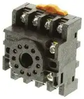


PF113A
RELAY SOCKET, DIN RAIL, 11PIN, SCREW
- Manufacturer: OMRON INDUSTRIAL AUTOMATION
- Product type: Relay Sockets
- No. of Pins: 11Pins
- Current Rating: 5A
- Voltage Rating: 250VAC
- Socket Mounting: DIN Rail
- Socket Terminals: Screw
| Delivery and price | |
|---|---|
| Units per pack | 100 |
| Price | 7.46 € |
| Current stock | 10+ |
| Lead time | 30 days |
omron ~~;~~

## **General-purpose Relay MK-I/-S**

## **Exceptionally Reliable General-purpose Relay Features Mechanical Indicator/Push Button**

- Breaks relatively large load currents despite small size.

- Long life (minimum 100,000 electrical operations) assured by silver contacts.

- Built-in operation indicator (Mechanical, LED), push button, diode surge suppression, varistor surge suppression.

- Standard models are UL, CSA, SEV, DEMKO, NEMKO, SEMKO, TÜV (IEC), and VDE.

- Conforming to CENELEC standards.

## **Model Number Structure**

## ■ **Model Number Legend**

## **Standard Models**

- **MK                  -      -** OOO UU **1 2 3 4 5 6**

## **1. Contact Form**

- 2: DPDT

- 3: 3PDT

## **2. Cover**

- P: Dust cover

## **3. Internal Connection Construction**

   - Blank: Standard

   - 2 or 5: Non-standard connection (Refer to _Terminal Arrangement/ Internal Connections)_

**4. Mechanical Indicator Push Button**

## **5. Approved Standards**

      - Blank: UL, CSA, DEMKO, NEMKO SEMKO, SEV, TÜV

      - VD: VDE

   **6. Rated Voltage** (Refer to _Coil Ratings_ )

- S: Mechanical indicator and push button

- I: Mechanical indicator

## **Special Accessories**

> **MK                       -      -      -** OOOO UU **1 2 3 4 5 6 7 8 1. Contact Form** 2: DPDT 3: 3PDT **2. Cover** P: Dust cover **3. Classification** N: LED indicator D: Diode V: Varistor ND: LED indicator and diode NV: LED indicator and varistor

**4. Coil Polarity**

## **1. Contact Form**

- Blank: Standard

- 1: Reverse (Refer to _Terminal Arrangement/ Internal Connections)_

## **2. Cover**

   **5. Internal Connection Construction**

**3. Classification**

- Blank: Standard

2 or 5: Non-standard connection (Refer to _Terminal Arrangement/ Internal Connections)_

**6. Mechanical Indicator Push Button**

   - S: Mechanical indicator and push button

   - I: Mechanical indicator

**7. Approved Standards**

   - Blank: UL and CSA only VD: VDE (N and D models only)

**8. Rated Voltage** (Refer to _Coil Ratings_ )

General-purpose Relay **MK-I/-S** A-45

## **Orderin Information g**

## ■ **List of Models**

|**Type**|**Terminal**|**Contact**<br>**form**|**Internal**<br>**connection**<br>**(see note 3)**|**With mechanical**<br>**indicator**|**With mechanical**<br>**indicator and**<br>**pushbutton**|**Coil ratings**|**Approved**<br>**standards**|
|---|---|---|---|---|---|---|---|
|**Standard**|Plug-in|DPDT|Standard|MK2P-I|MK2P-S|AC (~), DC (=)|UL, CSA, SEV,<br>DEMKO, NEM-<br>KO, SEMKO,<br>TÜV|
||||Non-standard|MK2P2-I|MK2P2-S|||
|||3PDT|Standard|MK3P-I|MK3P-S|||
||||Non-standard|MK3P2-I<br>MK3P5-I|MK3P2-S<br>MK3P5-S|||
|**LED Indicator**<br>**(see note 2)**||DPDT|Standard|MK2PN@-I|MK2PN@-S|AC (~), DC (=)|UL, CSA|
||||Non-standard|MK2PN@-2-I|MK2PN@-2-S|||
|||3PDT|Standard|MK3PN@-I|MK3PN@-S|||
||||Non-standard|MK3PN@-2-I<br>MK3PN@-5-I|MK3PN@-2-S<br>MK3PN@-5-S|||
|**Diode**<br>**(see note 2)**||DPDT|Standard|MK2PD@-I|MK2PD@-S|DC (=)|UL, CSA|
||||Non-standard|MK2PD@-2-I|MK2PD@-2-S|||
|||3PDT|Standard|MK3PD@-I|MK3PD@-S|||
||||Non-standard|MK3PD@-2-I<br>MK3PD@-5-I|MK3PD@-2-S<br>MK3PD@-5-S|||
|**Varistor**||DPDT|Standard|MK2PV-I|MK2PV-S|AC (~)|UL, CSA|
||||Non-standard|MK2PV-2-I|MK2PV-2-S|||
|||3PDT|Standard|MK3PV-I|MK3PV-S|||
||||Non-standard|MK3PV-2-I<br>MK3PV-5-I|MK3PV-2-S<br>MK3PV-5-S|||
|**VDE approved**||DPDT|Standard|MK2P-I-VD|MK2P-S-VD|AC (~), DC (=)|UL, CSA, SEV,<br>DEMKO, NEM-<br>KO, SEMKO,<br>TÜV,<br>VDE|
||||Non-standard|MK2P2-I-VD|MK2P2-S-VD|||
|||3PDT|Standard|MK3P-I-VD|MK3P-S-VD|||
||||Non-standard|MK3P2-I-VD MK3P5-<br>I-VD|MK3P2-S-VD<br>MK3P5-S-VD|||
|**LED Indicator**<br>**VDE approved**||DPDT|Standard|MK2PN-I-VD|MK2PN-S-VD|AC (~), DC (...)|UL, CSA, VDE|
||||Non-standard|MK2PN-2-I-VD|MK2PN-2-S-VD|||
|||3PDT|Standard|MK3PN-I-VD|MK3PN-S-VD|||
||||Non-standard|MK3PN-2-I-VD|MK3PN-2-S-VD|||
|||||MK3PN-5-I-VD|MK3PN-5-S-VD|||
|**Diode**<br>**VDE approved**||DPDT|Standard|MK2PD-I-VD|MK2PD-S-VD|DC (...)|UL, CSA, VDE|
||||Non-standard|MK2PD-2-I-VD|MK2PD-2-S-VD|||
|||3PDT|Standard|MK3PD-I-VD|MK3PD-S-VD|||
||||Non-standard|MK3PD-2-I-VD|MK3PD-2-S-VD|||
|||||MK3PD-5-I-VD|MK3PD-5-S-VD|||


**Note: 1.** When ordering, add the rated voltage to the model number. Rated voltages are given in the coil ratings table in _Specifications_ . Example: MK3P5-S 230 VAC

Rated voltage

**2.** This DC coil comes in two types: standard coil polarity and reversed coil polarity. Refer to _Terminal Arrangement/Internal Connections._ Example: MK2PN1-I 24 VDC

Reverse polarity

**3.** Refer to _Terminal Arrangement/Internal Connections_ for non-standard internal connection.

**4.** The gold plating thickness depends on the request. Example: MK3P-I AP3 24 VAC

Gold plating thickness: 3 µm

## ■ **Accessories (Order Separately)**

||**Item**|**Model**|
|---|---|---|
|Track-mounted<br>Socket|8-pin type|PF083A-E|
||11-pin type|PF113A-E|
|Hold-down Clip||PFC-A1|


General-purpose Relay **MK-I/-S**

A-46

## **S ecifications p**

## ■ **Coil Ratings**

## **UL, CSA, DEMKO, NEMKO, SEMKO, SEV, TÜV**

|**Rated**|**voltage**|**Rated current**|**Rated current**|**Coil resistance**|**Must operate**<br>**voltage**|**Must release**<br>**voltage**|**Max. voltage**|**Power**<br>**consumption**|
|---|---|---|---|---|---|---|---|---|
|||**60 Hz**|**50 Hz**||||||
|AC<br>(~)|6 V|360 mA|404 mA|3.9Ω|80% max. of rated<br>voltage|30% min. of rated<br>voltage|90% to110% of<br>rated voltage|Approx. 2.3 VA (at<br>60 Hz)<br>Approx. 2.7 VA<br>(at 50 Hz)|
||12 V|180 mA|202 mA|16.9Ω|||||
||24 V|88.0 mA|98.0 mA|62.0Ω|||||
||50 V|39.0 mA|46.3 mA|330Ω|||||
||100 V|24.8 mA|28.4 mA|1,010Ω|||||
||110 V|21.0 mA|24.7 mA|1,240Ω|||||
||120 V|18.0 mA|20.2 mA|1,520Ω|||||
||200 V|12.1 mA|14.2 mA|4,520Ω|||||
||220 V|11.0 mA|12.9 mA|5,130Ω|||||
||230 V|10.5 mA|12.3 mA|6,170Ω|||||
||240 V|9.2 mA|10.3 mA|6,450Ω|||||
|DC<br>(=)|6 V|255 mA||23.5Ω||15% min. of rated<br>voltage||Approx. 1.5 W|
||12 V|126 mA||95Ω|||||
||24 V|56 mA||430Ω|||||
||48 V|29.5 mA||1,630Ω|||||
||100 V|14.7 mA||6,800Ω|||||
||110 V|15.1 mA||7,300Ω|||||


## **VDE**

|**VDE**|||||||||
|---|---|---|---|---|---|---|---|---|
|**Rated**|**voltage**|**Rated current**||**Coil resistance**|**Must operate**<br>**voltage**|**Must release**<br>**voltage**|**Max. voltage**|**Power**<br>**consumption**|
|||**50 Hz**|**60 Hz**||||||
|AC<br>(~)|6 V|380 mA|325 mA|4.4Ω|80% max. of rated<br>voltage|30% min. of rated<br>voltage|90% to110% of<br>rated voltage|Approx. 2.0 VA (at<br>60 Hz)<br>Approx. 2.4 VA (at<br>50 Hz)|
||12 V|175 mA|145 mA|19.0Ω|||||
||24 V|91.0 mA|76.5 mA|70.7Ω|||||
||50 V|42.0 mA|36.0 mA|330Ω|||||
||100 V|24.0 mA|20.5 mA|1,150Ω|||||
||110 V|21.5 mA|18.0 mA|1,400Ω|||||
||120 V|20.0 mA|17.0 mA|1,600Ω|||||
||200 V|11.2 mA|9.4 mA|5,110Ω|||||
||220 V|10.2 mA|8.7 mA|5,800Ω|||||
||230 V|9.6 mA|8.1 mA|6,990Ω|||||
||240 V|9.4 mA|7.9 mA|7,400Ω|||||
|DC<br>(=)|6 V|225 mA||26.7Ω||15% min. of rated<br>voltage||Approx. 1.3 W|
||12 V|116 mA||107Ω|||||
||24 V|56.0 mA||440Ω|||||
||48 V|29.0 mA||1,660Ω|||||
||100 V|13.1 mA||7,660Ω|||||
||110 V|12.5 mA||8,720Ω|||||


- **Note: 1.** The rated current and coil resistance are measured at a coil temperature of 23°C with tolerances of +15%/−20% for AC rated current and ±15% for DC coil resistance.

   **2.** Performance characteristic data are measured at a coil temperature of 23°C.

   **3.** ~ indicates AC and = indicates DC (IEC417 publications).

   **4.** For 200 VDC applications, a 100-VDC Relay is supplied with a fixed 6.8 kΩ, 30 W resistor. Be sure to connect the resistor in series with the coil.

   **5.** For models with the LED indicator built in, add an LED current of approximately 0 through 5 mA to the rated current.

General-purpose Relay **MK-I/-S** A-47

## ■ **Contact Ratings**

|■**Contact Ratings**|||
|---|---|---|
|**Load**|Resistive load<br>(cosφ = 1)|Inductive load<br>(cosφ = 0.4)|
|**Contact mechanism**|Single||
|**Contact material**|Ag||
|**Rated load**|10 A at 250 VAC<br>10A at 28 VDC|7 A at 250 VAC|
|**Rated carry current**|10 A||
|**Max. switching voltage**|250 VAC, 250 VDC||
|**Max. switching current**|10 A||
|**Max. switching power**|2,500 VA, 280 W|1,750 VA|


## ■ **Characteristics**

|■**Characteristics**||
|---|---|
|**Contact resistance**|50 mΩmax.|
|**Operate time**|AC: 20 ms max. DC: 30 ms max.|
|**Release time**|20 ms max.|
|**Max. operating frequency**|Mechanical:18,000 operations/hr<br>Electrical:1,800 operations/hr (under rated load)|
|**Insulation resistance**|100 MΩmin. (at 500 VDC)|
|**Dielectric strength**|2,500 VAC, 50/60 Hz for 1 min between coil and contacts;<br>1,000 VAC, 50/60 Hz for 1 min between contacts of same polarity, terminals of the same polarity;<br>2,500 VAC, 50/60 Hz fro 1 min between current-carrying parts, non-current-carrying parts, and termi-<br>nals of opposite polarity|
|**Vibration resistance**|Destruction:10 to 55 to 10 Hz, 0.75-mm single amplitude (1.5-mm double amplitude)<br>Malfunction:10 to 55 to 10 Hz, 0.5-mm single amplitude (1.0-mm double amplitude)|
|**Shock resistance**|Destruction:1,000 m/s2(approx. 100G)<br>Malfunction:100 m/s2(approx. 10G);|
|**Endurance**|Mechanical:10,000,000 operations min. (at operating frequency of 18,000 operations/hour)<br>Electrical:Refer to_Engineering Data_.|
|**Error rate (reference value)**|10 mA at 1 VDC|
|**Ambient temperature**|Operating:–10°C to 40°C (with no icingor condensation)|
|**Ambient humidity**|Operating: 5% to 85%|
|**Weight**|Approx. 85g|


**Note:** The data shown are initial values.

General-purpose Relay **MK-I/-S**

A-48

## ■ **Approved Standards**

The following ratings apply to all models.

## **UL 508 (File No. E41515)/CSA 22.2 No.0/14 (File No. LR35535)**

|**Coil ratings**|**Contact ratings**|**Operations**|
|---|---|---|
|6 to 110 VDC<br>6 to 240 VAC|10 A, 28 VDC (resistive)<br>10 A, 250 VAC (resistive)<br>7 A, 250 VAC (general use)|100,000 cycles|
|**SEV, DEMKO, NEMKO**|||
|**Coil ratings**|**Contact ratings**|**Operations**|
|6 to 110 V=<br>6 to 240 V~|10 A, 250 V~(NO) (cosφ= 1)<br>5 A, 250 V~(NC) (cosφ= 1)<br>10 A, 28 V=(NO)<br>5 A, 28 V=(NC)<br>7 A, 250 V~(cosφ = 0.4)|100,000 cycles|
|**SEMKO**|||
|**Coil ratings**|**Contact ratings**|**Operations**|
|6 to 110 V=<br>6 to 240 V~|10 A, 250 V~(NO) (cosφ= 1)<br>5 A, 250 V~(NC) (cosφ = 1)|100,000 cycles|


## **’ - ’ ’ TÜV (VDE 0435 Teil 201/05 90, IEC 255 Teil 1 00/ 75, EN 60950/ 88**

## **(TÜV File No.: R9051410)**

|**Coil ratings**|**Contact ratings**|**Conditions**|**Operations**|
|---|---|---|---|
|6, 12, 24, 48, 100<br>110 V=<br>6, 12, 24, 50, 100, 110<br>115, 120, 200, 220<br>230, 240 V~|10 A, 250 V~(cosφ= 1)<br>10 A, 28 V=<br>7 A, 250 V~(cosφ= 0.4)|IEC 255-1-00 Item 3.1.4<br>Pollution Degree 3,<br>Overvoltage Category II<br>Pick up class - class 2<br>Temperature class - class b|100,000 cycles|


## **’ - ’ VDE (VDE 0435 Teil 201/05 83, IEC 255 Teil 1 00/ 75)**

## **(VDE File No.: NR 5340)**

|**Coil ratings**|**Contact ratings**|**Conditions**|**Operations**|
|---|---|---|---|
|6, 12, 24, 48, 100<br>110 V=<br>6, 12, 24, 50, 100, 110<br>115, 120, 200, 220<br>230, 240 V~|10 A, 250 V~(cosφ= 1)<br>10 A, 28 V=<br>7 A, 250 V~(cosφ=0.4)|C/250 - class 1, class C|100,000 cycles|


General-purpose Relay **MK-I/-S** A-49

**En ineerin Data g g**

**==> picture [481 x 260] intentionally omitted <==**

**----- Start of picture text -----**<br>
 Electrical Endurance  Maximum Switching Power<br>100<br>70 AC resistive load<br>5,000<br>50<br>3,000 28-VDC resistive load 30<br>DC resistive load<br>250-VAC resistive load<br>28 VDC max.<br>120-VAC resistive load<br>1,000 10<br>7<br>500 5<br>AC inductive<br>300 3 load<br>250-VAC<br>inductive<br>100 load st 1<br>10 30 50 70 100 300 500 700 1,000<br>50<br>Switching voltage (V)<br>30<br>10<br>0 2 4 6 8 10 12<br>Switching current (A)<br>3 operations)<br>Switching current (A)<br>Endurance (x10<br>**----- End of picture text -----**<br>


General-purpose Relay **MK-I/-S**

A-50

~~omron ;~~

## **Dimensions**

**Note:** All units are in millimeters unless otherwise indicated.

## ■ **Relays**

|■**Relays**|■**Relays**|■**Relays**||||
|---|---|---|---|---|---|
|34.5 max.<br>34.5 max.<br>~~w~~t|||0.8<br>52.5 max.<br> CE|||
|**Sockets**|**Sockets**|||||
|See below for Socket dimensions.||||||
|**Socket**||**Surface-mounting Socket**||||
|||**(for track or screw mounting)**||||
|||**Finger-protection**||**Finger-protection**|**---**|
|||**models**||||
|**Maximum**||10 A|||5 A|
|**carry current**||||||
|**2 poles**<br>PF083A-E<br>PF083A<br>~~po~~||||||
|**3 poles**||PF113A-E|||PF113A|


## **Sockets**

See below for Socket dimensions.

**Note:** Use the Surface-mounting Sockets (i.e., finger-protection models) with “-E” at the end of the model number. When using the PF083A and PF113A, be sure not to exceed the Socket’s maximum carry current of 5 A. Using at a current exceeding 5 A may lead to burning. Round terminals cannot be used for finger-protection models. Use Y-shaped terminals.

## **PF083A-E (Conforming to EN 50022)**

**==> picture [152 x 98] intentionally omitted <==**

**----- Start of picture text -----**<br>
Eight, M3.5 x 7 sems<br>7 4<br>plaielet 4<br>52 max. Hot vole: ae 35.4<br>33 3.5 2<br>41 max.<br>21 max.<br>**----- End of picture text -----**<br>


## **PF113A-E (Conforming to EN 50022)**

**==> picture [155 x 105] intentionally omitted <==**

**----- Start of picture text -----**<br>
Eleven, M3.5 x 7 sems<br>7 4<br>52 max. eel ft b 35.4<br>masclovel H :<br>4 34 3.5 2<br>42.8 max.<br>31 max.<br>**----- End of picture text -----**<br>


**==> picture [175 x 201] intentionally omitted <==**

**----- Start of picture text -----**<br>
Terminal Arrangement Mounting Holes<br>Two, M4 or two 4.5-dia. holes<br>YO OG<br>- Oo a 33±0.2<br>Two, M4 or two 4.5-dia. holes<br>eas} foo 33±0.2<br>**----- End of picture text -----**<br>


General-purpose Relay **MK-I/-S** A-51

## **Hold-down Clips**

## **PFC-A1**

## **Mounting Tracks**

**==> picture [215 x 148] intentionally omitted <==**

**----- Start of picture text -----**<br>
PFP-100N, PFP-50N<br>(Conforming to EN 50022)<br>—=<br>7.3±0.15<br>4.5<br>35±0.3 27±0.15<br>15 25 25 25 25 *<br>Pt tt 10 1000 (500)* L Jt 10 1<br>* This dimension applies to the PFP-50N Mounting Track.<br>**----- End of picture text -----**<br>


**PFP-100N2 (Conforming to EN 50022)**

**==> picture [242 x 54] intentionally omitted <==**

**----- Start of picture text -----**<br>
16<br>4.5<br>35±0.3 27 24 29.2<br>ee 15 25 10 25 1000±4 a 25 10 25 15 1 1.5<br>**----- End of picture text -----**<br>


- A total of twelve 25 x 4.5 elliptic holes is provided with six holes cut from each track end at a pitch of 10 mm.

## **Mounting Height with Sockets**

## **Surface-mounting Sockets**

**==> picture [244 x 100] intentionally omitted <==**

**----- Start of picture text -----**<br>
Three<br>77.8   Two  87.8  (See   poles<br>(See   poles note.) 84.3<br>note.) 74.3<br>PF083A(-E) PF113A(-E)<br>Note:  PF083A(-E) and PF113A(-E) allow either track or screw mount-<br>ing.<br>**----- End of picture text -----**<br>


General-purpose Relay **MK-I/-S**

A-52

## **Terminal Arrangement/Internal Connection (Bottom View)**

|**Standard**<br>**(AC/DC Coil)**<br>**VDE-approved Type**<br>**(AC/DC Coil)**<br>**( ): Dual Numbering**<br>**LED Indicator Type**<br>**(AC Coil)**||MK2P-I, -S||MK2P2-I, -S||MK3P-I, -S|MK3P-I, -S|MK3P-I, -S||MK3P2-I, -S|MK3P2-I, -S|MK3P2-I, -S|MK3P2-I, -S|MK3P5-I, -S|MK3P5-I, -S|
|---|---|---|---|---|---|---|---|---|---|---|---|---|---|---|---|
|||4<br>3<br>2<br>1<br>8<br>7<br>6<br>5||4<br>3<br>2<br>1<br>8<br>7<br>6<br>5|||1<br>2<br><br>5<br>|6<br>7<br>8<br>9<br>10<br>11|||||7<br>8<br>9<br>10<br>11|3<br>4|1<br>2<br>5<br>6<br>7<br>8<br>9<br>10<br>11|
|||||||3<br>4||||3<br>4|5<br>6|||||
|||||||||||||||||
|||||||||||||||||
|||||||||||||||||
|||||||||||||||||
||MK2P-I-VD, -S-VD||MK2P2-I-VD, -S-VD|||MK3P-I-VD, -S-VD|||MK3P2-I-VD, -S-VD|||||MK3P5-I-VD, -S-VD||
||4<br>3<br>2<br>1<br>8<br>7<br>6<br>5<br>(12)<br>(22)<br>(14)<br>(24)<br>(A1)<br>(A2)<br>(11)<br>(21)||4<br>3<br>2<br>1<br>8<br>7<br>6<br>5<br>(12)<br>(22)<br>(11)<br>(21)<br>(14)<br>(24)<br>(A1)<br>(A2)|||1<br>2<br>3<br>4<br>5<br>6<br>(12)<br>(14)<br>(21)<br>(11)<br>(2<br>(A1)||7<br>8<br>9<br>10<br>11<br>(22)<br>(32)<br>(34)<br>(31)<br>4)<br>(A2)||||||1<br>2<br>3<br>4<br>5<br>6<br>7<br>8<br>9<br>10<br>11<br>(22)<br>(24)<br>(12)<br>(32)<br>(14)<br>(34)<br>(11)<br>(31)<br>(21)<br>(A1)<br>(A2)||
|||||||||||||||||
|||||||||||||||||
|||MK2PN-I, -S|MK2PN-2-I, -S|||MK3PN-I, -S||||MK3PN-2-I, -S||||MK3PN-5-I, -S||
|||4<br>3<br>2<br>1<br>8<br>7<br>6<br>5||4<br>3<br>2<br>1<br>8<br>7<br>6<br>5|||1<br>2<br><br>5<br>|6<br>7<br>8<br>9<br>10<br>11|||||7<br>8<br>9<br>10<br>11|3<br>4|1<br>2<br>5<br>6<br>7<br>8<br>9<br>10<br>11|
|||||||3<br>4||||3<br>4|5<br>6|||||
|||||||||||||||||
|||||||||||||||||
|||||||||||||||||
|||||||||||||||||


General-purpose Relay **MK-I/-S** A-53

|**LED Indicator Type**<br>**(DC Coil:**<br>**Standard Polarity)**<br>**LED Indicator Type**<br>**(DC Coil:**<br>**Reverse Polarity)**<br>**Diode Type**<br>**(DC Coil:**<br>**Standard Polarity)**||MK2PN-I, -S|MK2PN-2-I, -S|MK2PN-2-I, -S||MK3PN-I, -S|MK3PN-I, -S|MK3PN-I, -S||MK3PN-2-I, -S|MK3PN-2-I, -S|MK3PN-5-I, -S|MK3PN-5-I, -S|
|---|---|---|---|---|---|---|---|---|---|---|---|---|---|
|||4<br>3<br>2<br>1<br>8<br>7<br>6<br>5<br>(+)<br>(−)||4<br>3<br>2<br>1<br>8<br>7<br>6<br>5<br>(+)<br>(−)|||1<br>2<br>5<br>|6<br>7<br>8<br>9<br>10<br>11<br>(−)|||6<br>7<br>8<br>9<br>10<br>11<br>(−)|1<br>2<br>3<br>4<br>5<br><br>(+)|6<br>7<br>8<br>9<br>10<br>11<br>(−)|
|||||||3<br>4||||1<br>2<br>3<br>4<br>5<br>(+)||||
||||||||(+)|||||||
|||||||||||||||
|||||||||||||||
|||MK2PN1-I, -S|MK2PN1-2-I, -S|||MK3PN1-I, -S||||MK3PN1-2-I, -S||MK3PN1-5-I, -S||
|||4<br>3<br>2<br>1<br>8<br>7<br>6<br>5<br>(+)<br>(−)||4<br>3<br>2<br>1<br>8<br>7<br>6<br>5<br>(−)<br>(+)|||1<br>2<br>5<br>|6<br>7<br>8<br>9<br>10<br>11<br>(+)|||6<br>7<br>8<br>9<br>10<br>11<br>(+)|1<br>2<br>3<br>4<br>5<br>(−)|6<br>7<br>8<br>9<br>10<br>11<br>(+)|
|||||||3<br>4||||1<br>2<br>3<br>4<br>5<br>(−)||||
||||||||(−)|||||||
|||||||||||||||
|||||||||||||||
|||MK2PD-I, -S|MK2PD-2-I, -S|||MK3PD-I, -S||||MK3PD-2-I, -S||MK3PD-5-I, -S||
|||4<br>3<br>2<br>1<br>8<br>7<br>6<br>5<br>(−)<br>(+)||4<br>3<br>2<br>1<br>8<br>7<br>6<br>5<br>(+)<br>(−)|||1<br>2<br>5<br>|6<br>7<br>8<br>9<br>10<br>11<br>(−)|||6<br>7<br>8<br>9<br>10<br>11<br>(−)|1<br>2<br>3<br>4<br>5<br><br>(+)|6<br>7<br>8<br>9<br>10<br>11<br>(−)|
|||||||3<br>4||||1<br>2<br>3<br>4<br>5<br>(+)||||
||||||||(+)|(−)||||||
|||||||||||||||
|**Diode Type**<br>**(DC Coil:**<br>**Reverse Polarity)**<br>**Varistor Type**<br>**(AC Coil)**||MK2PD1-I, -S|MK2PD1-2-I, -S|||MK3PD1-I, -S||||MK3PD1-2-I, -S||MK3PD1-5-I, -S||
|||4<br>3<br>2<br>1<br>8<br>7<br>6<br>5<br>(−)<br>(+)||4<br>3<br>2<br>1<br>8<br>7<br>6<br>5<br>(−)<br>(+)|||1<br>2<br>5<br>|6<br>7<br>8<br>9<br>10<br>11<br>(+)|||6<br>7<br>8<br>9<br>10<br>11<br>(+)|1<br>2<br>3<br>4<br>5<br>(−)|6<br>7<br>8<br>9<br>10<br>11<br>(+)|
|||||||3<br>4||||1<br>2<br>3<br>4<br>5<br>(−)||||
||||||||(−)|(+)||||||
|||||||||||||||
|||||||||||||||
|||MK2PV-I, -S|MK2PV-2-I, -S|||MK3PV-I, -S||||MK3PV-2-I, -S||MK3PV-5-I, -S||
|||4<br>3<br>2<br>1<br>8<br>7<br>6<br>5||4<br>3<br>2<br>1<br>8<br>7<br>6<br>5|||1<br>2<br>5<br>|6<br>7<br>8<br>9<br>10<br>11|||6<br>7<br>8<br>9<br>10<br>11|1<br>2<br>3<br>4<br>5|6<br>7<br>8<br>9<br>10<br>11|
|||||||3<br>4||||1<br>2<br>3<br>4<br>5||||
|||||||||||||||
|||||||||||||||


General-purpose Relay **MK-I/-S**

A-54

|**LED Indicator and**<br>**Diode Type**<br>**(DC Coil)**<br>**LED Indicator and**<br>**Varistor Type**<br>**(AC Coil)**|MK2PND-I, -S|MK2PND-I, -S|MK2PND-I, -S|MK2PND-2-I, -S|MK2PND-2-I, -S|MK2PND-2-I, -S||MK3PND-I, -S|MK3PND-I, -S||MK3PND-2-I, -S|MK3PND-2-I, -S|MK3PND-5-I, -S|MK3PND-5-I, -S|
|---|---|---|---|---|---|---|---|---|---|---|---|---|---|---|
|||4<br>3|8<br>7<br>6<br>5<br>(−)||4<br>3<br>2<br>1|8<br>7<br>6<br>5<br>(−)||1<br>2<br>3<br>4<br>5<br>(+)|6<br>7<br>8<br>9<br>10<br>11<br>(−)|||6<br>7<br>8<br>9<br>10<br>11<br>(−)|1<br>2<br>3<br>4<br>5<br><br>(+)|6<br>7<br>8<br>9<br>10<br>11<br>(−)|
||||||||||||1<br>2<br>3<br>4<br>5<br>(+)||||
|||2<br>1|||||||||||||
||||||||||||||||
|||||||(−)|||(−)|||(−)||(−)|
|||(+)|||||||||||||
||||||(+)||||||||||
||||||||||||||||
|||MK2PNV-I, -S||MK2PNV-2-I, -S||||MK3PNV-I, -S|||MK3PNV-2-I, -S||MK3PNV-5-I, -S||
|||4<br>3<br>2<br>1<br>8<br>7<br>6<br>5|||4<br>3<br>2<br>1<br>8<br>7<br>6<br>5|||1<br>2<br>3<br>4<br>5|6<br>7<br>8<br>9<br>10<br>11|||6<br>7<br>8<br>9<br>10<br>11|1<br>2<br>3<br>4<br>5|6<br>7<br>8<br>9<br>10<br>11|
||||||||||||1<br>2<br>3<br>4<br>5||||
||||||||||||||||
|**VDE Approved Type**<br>**LED Indicator Type**<br>**(DC Coil:**<br>**Standard Polarity)**<br>**( ): Dual Numbering**<br>**VDE Approved Type**<br>**LED Indicator Type**<br>**(DC Coil:**<br>**Reverse Polarity)**<br>**VDE Approved Type**<br>**Diode Type**<br>**(DC Coil:**<br>**Standard Polarity)**|MK2PN-I-VD, -3-VD<br>MK2PN-2-I-VD, -3-VD<br>MK3PN-I-VD, -S-VD<br>MK3PN-2-I-VD, -S-VD MK3PN-5-I-VD, -S-VD||||||||||||||
||4<br>3<br>2<br>1<br>8<br>7<br>6<br>5<br>(+)<br>(−)<br>(14)<br>(A1)<br>(11)<br>(21)<br>(A2)<br>(24)<br>(12)<br>(22)|||4<br>3<br>2<br>1<br>8<br>7<br>6<br>5<br>(+)<br>(−)<br>(14)<br>(A1)<br>(11)<br>(21)<br>(A2)<br>(24)<br>(12)<br>(22)|||1<br>2<br>3<br>4<br>5<br>(+)<br>(12)<br>(14)<br>(21)<br>(A1)<br>(11)<br>(||6<br>7<br>8<br>9<br>10<br>11<br>(−)<br>(22)<br>24)<br>(32)<br>(34)<br>(A2)<br>(31)||||1<br>2<br>3<br>4<br>5<br>6<br>7<br>8<br>9<br>10<br>11<br>(+)<br>(−)<br>(22)<br>(21)<br>(24)<br>(32)<br>(34)<br>(A2)<br>(31)<br>(11)<br>(A1)<br>(14)<br>(12)||
||||||||||||||||
||MK2PN1-I-VD, -S-VD|||MK2PN1-2-I-VD, -S-VD|||MK3PN1-I-VD, -S-VD|||MK3PN1-2-I-VD, -S-VD|||MK3PN1-5-I-VD, -S-VD||
||4<br>3<br>2<br>1<br>8<br>7<br>6<br>5<br>(+)<br>(−)<br>(12)<br>(22)<br>(14)<br>(A1)<br>(11)<br>(21)<br>(A2)<br>(24)|||4<br>3<br>2<br>1<br>8<br>7<br>6<br>5<br>(−)<br>(+)<br>(14)<br>(A1)<br>(11)<br>(21)<br>(A2)<br>(24)<br>(12)<br>(22)|||1<br>2<br>3<br>4<br>5<br>(−)<br>(12)<br>(14)<br>(21)<br>(A1)<br>(11<br>(||6<br>7<br>8<br>9<br>10<br>11<br>(+)<br>)<br>(22)<br>24)<br>(32)<br>(34)<br>(A2)<br>(31)||||1<br>2<br>3<br>4<br>5<br>6<br>7<br>8<br>9<br>10<br>11<br>(−)<br>(+)<br>(22)<br>(21)<br>(24)<br>(32)<br>(34)<br>(A2)<br>(31)<br>(11)<br>(A1)<br>(14)<br>(12)||
||||||||||||||||
||MK2PD-I-VD, -S-VD|||MK2PD-2-I-VD, -S-VD||||MK3PD-I-VD, -S-VD||MK3PD-2-I-VD, -S-VD|||MK3PD-5-I-VD, -S-VDS||
||4<br>3<br>2<br>1<br>8<br>7<br>6<br>5<br>(−)<br>(+)<br>(12)<br>(22)<br>(14)<br>(A1)<br>(11)<br>(21)<br>(A2)<br>(24)|||4<br>3<br>2<br>1<br>8<br>7<br>6<br>5<br>(+)<br>(−)<br>(14)<br>(A1)<br>(11)<br>(21)<br>(A2)<br>(24)<br>(12)<br>(22)|||1<br>2<br>3<br>4<br>5<br>(+)<br>(12)<br>(14)<br>(21)<br>(A1)<br>(11<br>(||6<br>7<br>8<br>9<br>10<br>11<br>(−)<br>)<br>(22)<br>24)<br>(32)<br>(34)<br>(A2)<br>(31)||||1<br>2<br>3<br>4<br>5<br>6<br>7<br>8<br>9<br>10<br>11<br>(+)<br>(−)<br>(22)<br>(21)<br>(24)<br>(32)<br>(34)<br>(A2)<br>(31)<br>(11)<br>(A1)<br>(14)<br>(12)||


General-purpose Relay **MK-I/-S** A-55

**==> picture [486 x 246] intentionally omitted <==**

**----- Start of picture text -----**<br>
VDE Approved Type  MK2PD1-I-VD, -S-VD MK2PD1-2-I-VD, -S-VD MK3PD1-I-VD, -S-VD MK3PD1-2-I-VD, -S-VD MK3PD1-5-I-VD, -S-VD<br>Diode Type<br>(DC Coil:  Reverse Polarity) (14) 3(12) 4 5 (22)6(24) (11)3(12)4 5 (22)6(21) (14)(12)4 5 (24)6 7(22)8 (32) (12)(11)4 5 (21)6 7(31)8(32) (12) (22)4 5 (21)6 7 (24)8 (32)<br>(A1)2 (11)1 (21)8 7(A2) (14)2 (A1)1 (A2)8 7 (24) (21)(A1)3 2(11)1 11(31)109(A2)(34) (24)(14)3(A1)2 1 11(A2)109(34)(22) (14)(A1)3 2(11)1 11(31)109(A2)(34)<br>(−) (+) (−) (+) (−) (+) (−) (+) (−) (+)<br>VDE Approved Type  MK2PN-I-VD, -S-VD MK2PN-2-I-VD, -S-VD MK3PN-I-VD, -S-VD MK3PN-2-I-VD, -S-VD MK3PN-5-I-VD, -S-VD<br>LED Indicator Type  (12) (22) (12) (22)<br>(AC Coil) (14) 3 4 5 6(24) (11)3 4 5 6(21) (14)(12)4 5 (24)6 7 (22)8 (32) (12)4(11)5 (21)6 7(31)8(32) (12) (22)4 5 (21)6 7 (24)8 (32)<br>(A1) 2 (11)1 (21)8 7(A2) (14)2 (A1)1 (A2)8 7 (24) (21)(A1)3 2(11)1 11(31)109(A2)(34) (14)(24)3(A1)2 1 11 (A2)109(34)(22) (14)(A1)3 2(11)1 11(31)109(A2)(34)<br>**----- End of picture text -----**<br>


ALL DIMENSIONS SHOWN ARE IN MILLIMETERS. To convert millimeters into inches, multiply by 0.03937. To convert grams into ounces, multiply by 0.03527.

Cat. No. J011-E1-06

In the interest of product improvement, specifications are subject to change without notice.

General-purpose Relay **MK-I/-S**

A-56
Updated at February 9, 2023
With a legacy spanning over 80 years, Omron Industrial Automation is a globally recognized leader in the manufacture of advanced industrial control and automation components. Renowned for their reliability and engineering excellence, Omron delivers comprehensive solutions that enhance efficiency, machine safety, and precision across a wide range of manufacturing environments. Our extensive portfolio of Omron products is heavily focused on their industry-leading sensing and switching technologies. We offer a vast selection of sensors, excelling specifically in high-performance proximity sensors, light sensors, and temperature sensors. Complementing this range are robust switching solutions, featuring a deep inventory of power relays, solid-state relays, safety relays, and essential relay accessories designed for demanding operational requirements. Beyond sensing and switching, Omron is highly regarded for its precision automation and process control equipment. Our selection features highly accurate temperature controllers, versatile process controllers, and sophisticated panel displays and instrumentation. To support these fundamental systems, we also supply dependable Omron power supplies, notably AC/DC converters, alongside vital connectivity components like DIN rail terminal blocks to ensure secure, efficient, and complete industrial setups.
About Novapart
Novapart is a B2B electronic component broker specialising in stock shortages and cost reduction. We source hard-to-find parts and identify compliant alternatives across a catalogue of 410,000+ components from 500+ manufacturers.
Learn more →Stock Shortage Specialist
When a component is unavailable, discontinued or has an unacceptable lead time, we tap into our network of vetted European and Asian distributors to source what you need — without compromising on quality or traceability.
Request a quote →Compliant Alternatives
We identify pin-to-pin, electrically equivalent substitutes that meet the same certifications (RoHS, AEC-Q100, REACH) as your original specification — validated against datasheets, not just part numbers. Often at a lower cost.
BOM Analysis service →