
Image not available
Illustrative purposes only

PE-205
Non Isolated POL DC/DC Converter, ITE & Industrial, Module, 1 Output, 4 W, 3.3 V, 1.2 A
⚠️ Reference pricing provided. In case of supply shortages, we will connect you with our trusted procurement partners to ensure your project's continuity.
- Manufacturer: BRAINBOXES
- Product type: DC / DC Non Isolated Board Mount Converters - Fixed Output
- SVHC: No SVHC (25-Jun-2025)
- Depth: 67.3mm
- Width: 66.7mm
- Height: 9.4mm
- Product Range: -
- No. of Outputs: 1 Output
- Output Power Max: 4W
- Output Current Max: 1.2A
- Output Voltage Nom: 3.3V
- Input Voltage DC Max: 30V
- Input Voltage DC Min: 5V
- DC / DC Converter Type: Module
- Power Supply Applications: ITE & Industrial
- DC / DC Converter Mounting: Surface Mount Device
- DC / DC Converter Output Type: Fixed
| Delivery and price | |
|---|---|
| Units per pack | 10 |
| Price | 38.78 € |
| Current stock | 10+ |
| Lead time | 30 days |
Datasheet

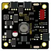
## brain|iboxes

PE-205 _Pure Embedded DC-DC Industrial Power Supply Module, 3.3 V, 4 W_

## 1 Overview

The perfect fit for any stable, future-proof system, even where space is limited

- DC-DC industrial power supply, 3.3 V, 4 W

- Supports modular stacking with PE-5XX Range

- Stability of design guaranteed compatibility until at least 2035 (Minimum 10 years)

- Seamless integration with design software – logical placements and fixed distances

- Power Output Control – Switch power outputs On/Off remotely

## 1.1 Functionality & Features

- Wide voltage input range: +5 to +30 VDC – Can be powered form a variety of sources

- +3.3 VDC Controllable Outputs – Natively compatible with Brainboxes PE Range

- Reverse Polarity Protected

- Short Circuit Protection

_Figure 1 – PE-205 Embedded Power Supply Module_

- Extremely compact 55x55 mm board size

- 2D & 3D design resources available

## 1.2 Specification

_Table 1 – General Information_

|_Table 1 – General Information_|_Table 1 – General Information_||
|---|---|---|
|**Input Voltage **||+5 V to +30 VDC|
|**Power Consumption**||5 W Max: 1 A@+5 VDC/167 mA@+30 VDC|
|**Output Voltage **||+3.3 VDC|
|**Max Output Current**||1.2 A(_see Table 15)_|
|**Max Power Output**||4 W|
|**Operating Temperature**||40 °C to +80 °C/-40 °F to +176 °F|
|**Storage Temperature**||40 °C to +80 °C/-40 °F to +176 °F|
|**Product Dimensions**||66.7 x 67.3 x 9.4 mm/2.62 x 2.64 x 0.4 in|
|**Product Weight**||0.022 kg /0.048 lbs|
|**Packaged Dimensions**||100 x 90 x 30 mm/3.3 x 3.5 x 1.2 in|
|**Packaged Weight**||0.031 kg /0.068 lbs|
|**Industry, EMC &**<br>**Immunity Compliance**|**General**|CE,UKCA,RoHS,REACH,WEEE|
||**GTIN**|837324005400|
||**HTS**|8504.40.85.00|
||**ECCN**|5A991.b|
||**Country of Origin(COO)**|Made in GB,United Kingdom of Great Britain & NI|
||**Safety**|IEC/EN/BS 62368-1|
||**EMC**|EN/BS 55032|
|||EN/BS 55035|


1

||**Flammability**|UL-94 V0|
|---|---|---|
||**RoHS**|2015/863/EU|
|||IEC/EN/BS 63000|
||||
||**REACH**|(EC)1907/2006|
||**Robustness**|EN 60068-2-31|


## 1.3 Connectors

The PE-205 board contains three spring clip power connectors & one 8-way female IDC style connector for power input & output:

_Table 2 – Male Header Compatibility_

|**Type **|**Manufacturer**|**Part Number**|
|---|---|---|
|3-pin|Phoenix Contact|1778845|
|8-way|TE|338728-8|


_Table 3 – Connector Wiring Guide_

|**Connector/Pin**|**1**|**2**|**3**|**4**|**5**|**6**|**7**|**8**|
|---|---|---|---|---|---|---|---|---|
|**Power Input**|FE|-VIN|+VIN||||||
|**+VA Power**|FE|+VIN|-VIN|Pass-<br>Through||Pass-<br>Through|-VOUT|+VAOUT|
|**Output**|||||||||
|**+VB Power**|FE|-VOUT|+VBOUT||||||
|**Output**|||||||||
||||||||||
|**Digital Output**|VACTL|-VOUT|VBCTL||||||
|**Control**|||||||||


## 2 Ordering

_Table 4 – Ordering Information_

|**Product Code**|**Description**|
|---|---|
|PE-405|Pure Embedded 10/100 5 Port Industrial Ethernet Eval Kit|
|PE-505|Pure Embedded 10/100 5 Port Industrial Ethernet Switch|
|PE-508|Pure Embedded 10/100 8 Port Industrial Ethernet Switch|
|PE-415|Pure Embedded Gigabit 5 Port Industrial Ethernet Evaluation Kit|
|PE-515|Pure Embedded Gigabit 5 Port Industrial Ethernet Switch|
|PE-205|Pure Embedded DC-DC Industrial Power Supply Module, 3.3 V,<br>4 W|


2

|3|Table of Contents|Table of Contents|
|---|---|---|
|1|Overview ........................................................................................................................................................ 1||
||1.1|Functionality & Features ...................................................................................................................... 1|
||1.2|Specification ......................................................................................................................................... 1|
||1.3|Connectors ........................................................................................................................................... 2|
|2|Ordering ......................................................................................................................................................... 2||
|3|Table of Contents ........................................................................................................................................... 3||
|4|List of Tables ................................................................................................................................................... 4||
|5|List of Figures.................................................................................................................................................. 4||
|6|PE-205 Pure Embedded DC-DC Industrial Power Supply Module ................................................................... 5||
|7|Design Guide .................................................................................................................................................. 6||
||7.1|Device Markings ................................................................................................................................... 6|
||7.2|Connectors & Pinouts........................................................................................................................... 6|
||7.2.1|A – VDC Power Input ....................................................................................................................... 6|
||7.2.2|B – Power Output Control ............................................................................................................... 6|
||7.2.3|D – VA Power Output ...................................................................................................................... 7|
||7.2.4|E – VB Power Output ....................................................................................................................... 7|
||7.3|Switches ............................................................................................................................................... 7|
||7.3.1|VA & VB Power Output Logic Switches ............................................................................................ 7|
||7.4|LED’s.....................................................................................................................................................8|
||7.4.1|Power Input ..................................................................................................................................... 8|
||7.4.2|VA & VB Power Output.................................................................................................................... 8|
||7.4.3|VA & VB Fault LED’s.........................................................................................................................8|
||7.5|Mounting Holes .................................................................................................................................... 8|
||7.6|Mechanical Outline & 3D Step Model .................................................................................................. 8|
||7.7|Recommended Footprint ................................................................................................................... 10|
|8|Operation ..................................................................................................................................................... 10||
||8.1|Verifying Power Output ..................................................................................................................... 10|
||8.1.1|Power Input ................................................................................................................................... 10|
||8.1.2|VA Power Output .......................................................................................................................... 10|
||8.1.3|VB Power Output .......................................................................................................................... 10|
||8.2|PE Range Modular Stacking ................................................................................................................ 11|
||8.2.1|PE-505 ........................................................................................................................................... 11|
||8.2.2|PE-515 ........................................................................................................................................... 11|
||8.2.3|PE-508 ........................................................................................................................................... 11|
|9|Operating Conditions .............................................................................................................................. 12||


3

|9.1<br>Absolute Maximum Ratings ............................................................................................................... 12|
|---|
|9.2<br>Electrical Characteristics .................................................................................................................... 12|
|10<br>Stability of Design Guarantee ................................................................................................................. 12|
|4 List of Tables|
|Table 1 – General Information ................................................................................................................................ 1|
|Table 2 – Male Header Compatibility ...................................................................................................................... 2|
|Table 3 – Connector Wiring Guide ........................................................................................................................... 2|
|Table 4 – Ordering Information ............................................................................................................................... 2|
|Table 5 – VDC Power Input ...................................................................................................................................... 6|
|Table 6 – Digital Power Output Control .................................................................................................................. 6|
|Table 7 – VA Power Output Pinouts ........................................................................................................................ 7|
|Table 8 – VB Power Output Pinouts ........................................................................................................................ 7|
|Table 9 – VA & VB Power Output Logic Switches .................................................................................................... 7|
|Table 10 – Power Input LED .................................................................................................................................... 8|
|Table 11 – VA & VB Power Output LED's ................................................................................................................. 8|
|Table 12 – VA & VB Power Output Fault LED's ........................................................................................................ 8|
|Table 13 – Absolute Maximum Ratings ................................................................................................................. 12|
|Table 14 – Typical Electrical Characteristics .......................................................................................................... 12|
|5 List of Figures|
|Figure 1 – PE-205 Embedded Power Supply Module|
|Figure 2 – PE-205..................................................................................................................................................... 5|
|Figure 3 – PE-205_Front Annotated Features ......................................................................................................... 6|
|Figure 4 – PE-205_Rear Annotated Features .......................................................................................................... 6|
|Figure 5 – PE-205 2D Dimensioned Drawing ........................................................................................................... 9|
|Figure 6 – PE-205 Modularly Stacked with PE-505 .................................................................................................. 9|
|Figure 7 – PE-205 Modularly Stacked with PE-515 .................................................................................................. 9|
|Figure 8 – PE-205 Power Input & Output Pinouts ................................................................................................. 10|
|Figure 9 – PE-505 Modular Stacking Header Pad Location .................................................................................... 11|
|Figure 10 – PE-505 Modularly Stacked with PE-205 .............................................................................................. 11|
|Figure 11 – PE-515 Modular Stacking Header Pad Location .................................................................................. 11|
|Figure 12 – PE-515 Modularly Stacked with PE-515 .............................................................................................. 11|


4

## 6 PE-205 Pure Embedded DC-DC Industrial Power Supply Module

The PE-205 is a compact, industrial DC-DC power supply module offering a wide +5 to +30 VDC input range, with two 3.3 V outputs, designed to allow seamless integration with Brainboxes’ Pure Embedded (PE) range of compact industrial switches, or any other low voltage device where space is a premium.

The PE-205 provides one +5 to +30 VDC input through a 3-pin connector, and two 3.3 V outputs, the first through a 3-pin connector & the second through an 8-way IDC style connector. The 8-way IDC connector enables modular stacking with select products from the PE range ( _see Section 9.2 below for more details_ ).

The PE-205 also offers Digital Power Control, enabling remote control of the two 3.3 V power outputs. These operate using NPN/PNP logic and could be easily integrated with Brainboxes’ Ethernet to Digital (ED) range ( _see Section 8.2.2 for more details_ ).

_Figure 2 – PE-205_

5

## 7 Design Guide

## 7.1 Device Markings

_Figure 3 – PE-205_Front Annotated Features_

_Figure 4 – PE-205_Rear Annotated Features_

- A +5 to +30 VDC Power Input

   - J Serial Number Label

- B Power Output Control

- C VA Power Output Logic Switch

- D VA Power Output

- E VB Power Output

- F VB Power Output Logic Switch

- G PCB Revision

- H NC Mounting Hole

- I FE Mounting Holes

## 7.2 Connectors & Pinouts

## 7.2.1 A – VDC Power Input

_Table 5 – VDC Power Input_

|Connectors & Pinouts<br>A – VDC Power Input<br>_Table 5 – VDC Power Input_|||
|---|---|---|
|**Pin**<br>1<br>2<br>3|**Function**||
||FE|Functional Earth|
||-VIN|GND/0 V|
||+VIN|+5 to +30 VDC|


## 7.2.2 B – Power Output Control

_Table 6 – Digital Power Output Control_

|**Pin**|**Function**|
|---|---|
|1|+VACTL|
|2|-VOUT(Reference)|
|3|+VBCTL|


6

The PE-205’s +VA & +VB power outputs can both be digitally controlled through the Digital Power Control connector ( _see ‘B’ on Figure 3_ ). The connector has a -Vout reference and two control pins (VACTL and one for VBCTL).

In addition to the Digital Power Control connector, each power supply also has a physical On/Off switch ( _see ‘C’ & ‘F’ on Figure 3_ ), which are used to define the operational behaviour of the power outputs. Both the VA & VB power outputs behave using NPN/PNP style logic, and will either deliver power when idle, or require driving High (PNP) or pulling Low (NPN) to deliver power ( _see Table 10_ ).

The logic levels for the Digital Power Control VA & VB pins are as follows:

- Logic Level 0 = 0 V to +1 VDC

- Logic Level 1 = +5 V to +30 VDC

All Voltages are given in respect to the -Vout Reference

## 7.2.3 D – VA Power Output

_Table 7 – VA Power Output Pinouts_

|**Pin**|**Function**|**Function**|
|---|---|---|
|1|FE|Functional Earth|
|2|+VIN|+5 to +30 VDC|
|3|-VIN|GND/0 V*|
|4|Passthrough|NC|
|5|-VOUT|0 V*|
|6|Passthrough|NC|
|7|-VOUT|0 V*|
|8|+VAOUT|+3.3 V|


- *-VIN and -Vout connected internally on the PE-205. For the product to perform to the stated specification, maintain separate power domains for -VIN and -VOUT.

## 7.2.4 E – VB Power Output

_Table 8 – VB Power Output Pinouts_

|**Pin**|**Function**|**Function**|
|---|---|---|
|1|FE|Functional Earth|
|2|-VOUT|0 V|
|3|+VBOUT|+3.3 V|


## 7.3 Switches

## 7.3.1 VA & VB Power Output Logic Switches

_Table 9 – VA & VB Power Output Logic Switches_

|**Position**|**Function**|**Function**|
|---|---|---|
|On|On – Idle|NPN|
||Off – Pulled Low||
|Off|On – Driven High|PNP|
||Off – Idle||


7

## 7.4 LED’s

## 7.4.1 Power Input

_Table 10 – Power Input LED_

|**LED State**|**Function**|
|---|---|
|Off|No Power|
|On – Green|Powered – Device OK|


## 7.4.2 VA & VB Power Output

_Table 11 – VA & VB Power Output LED's_

|**LED State**|**Function**|
|---|---|
|Off|Power DeliveryDisabled|
|On – Green|Power DeliveryEnabled|


## 7.4.3 VA & VB Fault LED’s

_Table 12 – VA & VB Power Output Fault LED's_

|**LED State**|**Function**|
|---|---|
|Off|No Issues|
|On – Red|Power Fault|


## 7.5 Mounting Holes

The PE-205 has 4 x M3 mounting holes, with each being connected to Functional Earth (FE). The top-left mounting hole (indicated by the yellow corner on the PCB) is floating to maintain -Vout as a separate power domain while stacked. The remaining 3 mounting holes are connected to Functional Earth.

If the device does not share a common ground with the rest of the system, it is recommended to use a nonconductive standoff or isolated mounting point.

## 7.6 Mechanical Outline & 3D Step Model

A scale drawing is available in this document on Page 9, while a 3D Step model is available on our website at the following link: https://www.brainboxes.com/product/pure-embedded/pe-205#3d-model

8

**==> picture [153 x 214] intentionally omitted <==**

**----- Start of picture text -----**<br>
i<br>if<br>ioema al<br>of __|<br>ob #0<br>PE<br>**----- End of picture text -----**<br>


_Figure 5 – PE-205 2D Dimensioned Drawing_

_Figure 6 – PE-205 Modularly Stacked with PE-505_

**==> picture [102 x 23] intentionally omitted <==**

**----- Start of picture text -----**<br>
SY<br>**----- End of picture text -----**<br>


_Figure 7 – PE-205 Modularly Stacked with PE-515_

9

## 7.7 Recommended Footprint

For applications where the module is frequently inserted and removed a through-hole mating connector is recommended. Avoid placing components within the 55 x 55 square occupied by the PE-205 where possible. Where not possible, ensure that the ‘Keepout’ zone given in the 3D Model of the Design Kit is strictly adhered to. Failure to do so has the potential to cause issues with future compatibility.

The device should be given 20 mm of clearance from the mating surface.

Alternatively, an 8-way IDC style header ( _as detailed in Section 1.3 above_ ) can be used for the VA power header, with the following centre coordinates: (2,35.5)

The 4x M3 mounting holes are located at: (0,0), (45,0), (0,45 – NC) & (45,45)

## 8 Operation

## 8.1 Verifying Power Output

The PE-205 accepts a wide input voltage ( _see ‘A’ on Figure 3_ ) and provides two 3.3 V outputs ( _see ‘D’ & ‘E’ on Figure 3_ ).

If an issue develops and your PE-205 isn’t distributing power to external devices correctly, measuring the voltage input and outputs may identify the problem. Using a Digital Multi Meter (DMM), verify that a voltage is present between the following pins:

## 8.1.1 Power Input

Measure between the +Vin & -VIN pins and verify supply voltage is present

## 8.1.2 VA Power Output

Measure between the +VAOUT and -VOUT pins and verify 3.3 V is present

## 8.1.3 VB Power Output

Measure between the +VBOUT & -VOUT pins and verify 3.3 V is present

_Figure 8 – PE-205 Power Input & Output Pinouts_

10

## 8.2 PE Range Modular Stacking

The PE-205’s design allows for native modular stacking with the PE-505 & PE-515 network switches. Using the VA Power Output header ( _see ‘D’ on Figure 4_ ), a board-to-board connection can be made to deliver power to the PE-505 & PE-515.

## 8.2.1 PE-505

The PE-505 has a footprint on the rear of the PCB, intended for a female 8-way IDC style connector ( **TE: 338728-8** ). If desired, once fitted to the board, the PE-505 can be modularly stacked with the PE205.

**==> picture [334 x 18] intentionally omitted <==**

**----- Start of picture text -----**<br>
Figure 9 – PE-505 Modular Stacking Header  Figure 10 – PE-505 Modularly Stacked with<br>Pad Location PE-205<br>**----- End of picture text -----**<br>


## 8.2.2 PE-515

The PE-515 is manufactured with a female 8-way IDC style connector

( **TE: 338728-8** ), fitted to the rear of the PCB. This allows for direct out of the box modular stacking with the PE-205.

_Figure 11 – PE-515 Modular Stacking Header Pad Location_

_Figure 12 – PE-515 Modularly Stacked with PE-515_

## 8.2.3 PE-508

The PE-508 does not support modular stacking.

11

## 9 Operating Conditions

## 9.1 Absolute Maximum Ratings

Stresses exceeding absolute maximum ratings may cause permanent damage. Functional performance and device reliability are not guaranteed under these conditions. All voltages are specified with respect to GND.

_Table 13 – Absolute Maximum Ratings_

|**Parameter**|**Max**|**Unit**|**Notes**|
|---|---|---|---|
|SupplyVoltage|34|V|-|
|IO Voltages|30|V|-|
|Ambient<br>Operating<br>Temperature|-40 to +85|°C|-|


## 9.2 Electrical Characteristics

_Table 14 – Typical Electrical Characteristics_

|**Parameter**|**Symbol**|**Min**|**Typical**|**Max**|**Unit**|**Notes**|
|---|---|---|---|---|---|---|
|DC Input<br>Voltage|VIN|5||30|V||
|DC Current|IIN|||1|A|VIN<br>@5 V|
|||||0.4|A|VIN<br>@12 V|
|||||0.15|A|VIN<br>@30 V|
||||||||
|CTL High||5|VIN|30|V||
|CTL Low||0|0|1|V||
||||||||
|VA Output|+VAOUT|3.25|3.3|3.4|V||
|VA Overload|IAMAX||1||A|Overload<br>Cut-off|
||||||||
|VB Output|+VBOUT|3.25|3.3|3.4|V||
|VB Overload|IBMAX||0.2||A|Overload<br>Cut-off|


## 10 Stability of Design Guarantee

Brainboxes guarantees that all our off-the-shelf embedded board products will remain available for a minimum of 10 years from the initial launch date. Our Change Control Policy, along with other regulatory documents, can be found here: https://www.brainboxes.com/regulatory-declarations

12
Updated at April 23, 2026
About Novapart
Novapart is a B2B electronic component broker specialising in stock shortages and cost reduction. We source hard-to-find parts and identify compliant alternatives across a catalogue of 410,000+ components from 500+ manufacturers.
Learn more →Stock Shortage Specialist
When a component is unavailable, discontinued or has an unacceptable lead time, we tap into our network of vetted European and Asian distributors to source what you need — without compromising on quality or traceability.
Request a quote →Compliant Alternatives
We identify pin-to-pin, electrically equivalent substitutes that meet the same certifications (RoHS, AEC-Q100, REACH) as your original specification — validated against datasheets, not just part numbers. Often at a lower cost.
BOM Analysis service →