
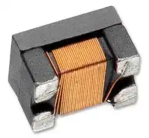

PE-1812ACC101STS
Choke, Common Mode, 100µH, 200mA, 7.5kohm, 200mA4.5mm L x 3.2mm W x 3mm H
- Manufacturer: PULSE ELECTRONICS
- Product type: SMD Common Mode Chokes / Filters
- Available until stocks are exhausted
- SVHC: To Be Advised
- Impedance: 7.5kohm
- Inductance: 100µH
- Product Range: 1812 ACC Series
- Product Width: 3.2mm
- Qualification: AEC-Q200
- Product Height: 3mm
- Product Length: 4.5mm
- DC Current Rating: 200mA
- DC Resistance Max: 2ohm
- Common Mode Filter Case: 4.5mm x 3.2mm x 3mm
- Inductor Case / Package: -
- Operating Temperature Max: 125°C
- Operating Temperature Min: -40°C
| Delivery and price | |
|---|---|
| Units per pack | 1000 |
| Price | 0.282 € |
| Current stock | 10+ |
| Lead time | 30 days |
## Automotive Chip Choke EMI Suppression for CAN-Bus Networks 2-Line Common Mode Chokes

_Meets AEC-Q200 Requirements_

- _Suppression of common mode noise without attenuating the signal_

_Magnetically shielded versions for lower Rdc and higher current Supports CAN-Bus, A2B and other IVN high speed differential signal lines (LVDS)_

**==> picture [510 x 406] intentionally omitted <==**

**----- Start of picture text -----**<br>
||||||||||||
|---|---|---|---|---|---|---|---|---|---|---|
|Electrical Specifications @ 25°C|
|Common Mode Impedance|Isolation|Rated|
|Inductance|Standard|RDC|IDC|
|(10MHZ)|Resistance|Voltage|
|(uH)|Tolerance|(|Ω|Max)|(A MAX)|
|Part Number|Min|Typ|(M|Ω|) Min|(V) Max|
|PE-1812ACCXXXSTS|Operating Temperature Range -40°C to +125°C|
|PE-1812ACC110STS|300|600|11|+50/-30%|0.5|0.36|10|50|
|PE-1812ACC220STS|600|1200|22|+50/-30%|0.6|0.31|10|50|
|PE-1812ACC510STS|1500|3500|51|+50/-30%|1|0.23|10|50|
|PE-1812ACC101STS|3000|7500|100|+50/-30%|2|0.2|10|50|
|Mechanical|Schematic|
|2|3|1|4|
|A|
|E|
|oo|ae|2|O@0000|
|C|
|2|3|
|view from PCB|
|B|1|4|PIN 1|
|fac]|D|-O|
|~~|Cl S|W)|
|S|oP!|Tit|
|F|
|All Units in mm|Bifilar winding|W|S|
|(representation only)|
|T|
|X|
|Component Dimensions (mm)|SOLDER PAD (mm)|
|Series|A|B|C|D|E|F|X|T|W|S|
|1812 ACC|4.5 +/-0.20|3.2 +/-0.20|3.0 MAX|3.1+/-0.20|0.65+/-0.15|0.70+/-0.15|5.90|3.20|3.40|1.60|

**----- End of picture text -----**<br>


1 **e** s

W717.J (04/24) e

PulseElectronics.com 1

## Automotive Chip Choke EMI Suppression for CAN-Bus Networks 2-Line Common Mode Chokes

**==> picture [109 x 53] intentionally omitted <==**

## **Impedance vs Frequency**

## **Temp vs DC Current**

## **PE-1812ACC110STS**

**==> picture [230 x 190] intentionally omitted <==**

**----- Start of picture text -----**<br>
Common mode Differen�al mode<br>10,000<br>1,000<br>11uH<br>100<br>10<br>1<br>0.1<br>1 10 100 1,000<br>Frequency(MHz)<br>Impedance (Ω)<br>**----- End of picture text -----**<br>


**==> picture [228 x 188] intentionally omitted <==**

**----- Start of picture text -----**<br>
�T@25 ͦC<br>60.0<br>50.0<br>11uH<br>40.0<br>30.0<br>20.0<br>10.0<br>0.0<br>0.0 0.2 0.4 0.6 0.8 1.0<br>IDC(A)<br>T (  ͦC)<br>�<br>**----- End of picture text -----**<br>


## **PE-1812ACC220STS**

**==> picture [230 x 188] intentionally omitted <==**

**----- Start of picture text -----**<br>
Common mode Differen�al mode<br>10,000.0<br>22uH<br>1,000.0<br>100.0<br>10.0<br>1.0<br>0.1<br>1 10 100 1,000<br>Frequency(MHz)<br>Impedance(Ω)<br>**----- End of picture text -----**<br>


**==> picture [230 x 186] intentionally omitted <==**

**----- Start of picture text -----**<br>
�T@25℃<br>60.0<br>50.0<br>22uH<br>40.0<br>30.0<br>20.0<br>10.0<br>0.0<br>0.0 0.2 0.4 0.6 0.8<br>IDC(A)<br>T (  ͦC)<br>�<br>**----- End of picture text -----**<br>


W717.J (04/24)

PulseElectronics.com

2

## Automotive Chip Choke EMI Suppression for CAN-Bus Networks 2-Line Common Mode Chokes

**==> picture [109 x 53] intentionally omitted <==**

## **Impedance vs Frequency**

## **Temp vs DC Current**

## **PE-1812ACC510STS**

**==> picture [254 x 186] intentionally omitted <==**

**----- Start of picture text -----**<br>
Common mode Differen�al mode<br>100,000.0<br>10,000.0<br>51uH<br>100.0<br>10.0<br>1.0<br>1 10 100 1,000<br>Frequency(MHz)<br>Impedance(Ω)<br>**----- End of picture text -----**<br>


**==> picture [217 x 179] intentionally omitted <==**

**----- Start of picture text -----**<br>
�T@25℃<br>70.0<br>60.0<br>50.0 51uH<br>40.0<br>30.0<br>20.0<br>10.0<br>0.0<br>0.0 0.1 0.2 0.3 0.4 0.5 0.6 0.7<br>IDC(A)<br>)℃<br>T(<br>�<br>**----- End of picture text -----**<br>


## **PE-1812ACC101STS**

**==> picture [254 x 186] intentionally omitted <==**

**----- Start of picture text -----**<br>
Common mode Differen�al mode<br>100,000.0<br>10,000.0<br>100uH<br>1,000.0<br>100.0<br>10.0<br>1.0<br>1 10 100 1,000<br>Frequency(MHz)<br>Impedance(Ω)<br>**----- End of picture text -----**<br>


**==> picture [218 x 181] intentionally omitted <==**

**----- Start of picture text -----**<br>
�T@25℃<br>60.0<br>50.0<br>100uH<br>40.0<br>30.0<br>20.0<br>10.0<br>0.0<br>0.00 0.10 0.20 0.30 0.40 0.50<br>IDC(A)<br>T (  ͦC)<br>�<br>**----- End of picture text -----**<br>


W717.J (04/24)

PulseElectronics.com

3

## Automotive Chip Choke EMI Suppression for CAN-Bus Networks 2-Line Common Mode Chokes

**==> picture [109 x 53] intentionally omitted <==**

## Reliability Test

|Reliability Test||||
|---|---|---|---|
|**Item**|**Reference documents**|**Test Condition**|**Test Specifcation**|
|1. High Temperature Exposure|MIL-STD-202 Method 108|1. Temperature: 125_�_C<br>2. Time: 1000 hours|1. No mechanical and electrical damage<br>2. Inductance shall be within specifcation|
|2. Temperature Cycling|JESD22 Method JA-104|1. Temperature: -40_�_C**~**125_�_C<br>2. Number of cycles: 1000 cycle<br>3.Dwell time: 30 minutes|1. No mechanical and electrical damage<br>2. Inductance shall be within specifcation|
|3. Biased Humidity Test|MIL-STD-202 Method 103|1. Temperature: 85±5_�_C<br>2. Time: 1000 hours<br>3. Humidity: 85±5% RH|1. No mechanical and electrical damage<br>2. Inductance shall be within specifcation|
|4. Operational Life|MIL-PRF-27|1. Temperature: 125_�_C<br>2. Time: 1000 hours<br>3. ApplyDC current reference|1. No mechanical and electrical damage<br>2. Inductance shall be within specifcation|
|5. External Visual|MIL-STD-883 Method 2009|Inspect product construction, marking and<br>workmanship|Per product specifcation standard|
|6. Physical Dimensions|JESD22 Method JB-100|Verify physical dimensions to the applicable product<br>detail specifcation|Per product specifcation standard|
|7. Vibration Test|MIL-STD-202 Method 204|1. Frequency and Amplifed: 10-2000-10 Hz, 1.5mm<br>2. Direction: X, Y, Z<br>3. Test duration: 2 hours for each direction,6 hours in total|1. No mechanical and electrical damage<br>2. Inductance shall be within specifcation|
|8. Resistance to Soldering<br>Heat Test|MIL-STD-202 Method 210|1. Temperature: 250±5_�_C<br>2. Time: (temp.≥217_�_C) 60-160 seconds<br>3. IR refow times: 3 times|1. No mechanical and electrical damage<br>2. Inductance shall be within specifcation|
|9. Solderability Test|J-STD-002|1. Bakeing in pre-testing: 150±5_�_C / 16Hours±30min.<br>2. Peak temperature: 245_�_C<br>3. Time: (temp.≥217_�_C) 60-160 seconds<br>4. IR refow times: 1 time|The terminal shall be at least 95% covered with<br>fresh solder.|
|10. Electrical Characterization|User Spec.|1. Operating temperature: -40_�_C**~**125_�_C<br>2. Room Temperature: 25_�_C|1. No mechanical and electrical damage<br>2. Inductance shall be within specifcation|
|11. Mechanical Shock|MIL-STD-202 Method 213|Figure 1 of Method 213. Condition C|1. No mechanical and electrical damage<br>2. Inductance shall be within specifcation|
|12. Board Flex Test|AEC-Q200-005|60 Seconds minimum holding time|After test, inductors shall be no mechanical damage.|
|13. Terminal Strength Test|AEC-Q200-006|1. Apply push force to samples mounted on PCB.<br>2. Force of 1.8 kg for 60±1 seconds.|After test, inductors shall be no mechanical damage.|


## **Notes:**

1. Inductance is measure, where applicable, with both primary windings connected in series (2 to 5, with 3 and 4 shorted).

2. Leakage inductance is measured with both primary windings connected in series (where applicable) with all other windings shorted.

W717.J (04/24)

PulseElectronics.com

4

## Automotive Chip Choke EMI Suppression for CAN-Bus Networks 2-Line Common Mode Chokes

## **Tape and Reel Specifications**

**==> picture [95 x 127] intentionally omitted <==**

**==> picture [197 x 80] intentionally omitted <==**

|||**Reel Dimensions(mm)**|**Reel Dimensions(mm)**|**Reel Dimensions(mm)**|**Reel Dimensions(mm)**|**Reel Dimensions(mm)**|**Tape Dimensions(mm)**|**Tape Dimensions(mm)**|**Tape Dimensions(mm)**|**Tape Dimensions(mm)**|**Tape Dimensions(mm)**|**Tape Dimensions(mm)**|
|---|---|---|---|---|---|---|---|---|---|---|---|---|
|**Series**|**Parts per Reel**|**A**<br>**B**<br>**C**<br>**D**<br>**E**|||||**W**<br>**P1**<br>**P2**<br>**P3**<br>**H**<br>**T**||||||
|1812 ACC|500|178|60|13|17|14|12|2|8|4|4|0.35|


## **Recommended Solder Heat Resistance Profile**

## **I. Description:**

a. Ferrite drum core construction

b. Magnetically shielded

- c.  Enameled copper wire:  H class

- d. Product weight:  0.15g (ref.)

e. Moisture sensitivity Level 1

f. Products comply with RoHS’ requirements

g. Halogen Free available

## **II. General specification:**

a. Storage temp:  -40 _�_ C to +125 _�_ C

b. Operating temp:  -40 _�_ C to +125 _�_ C

(Temp. rise included)

c. Resistance to solder heat: 250 _�_ C  10 secs.

**==> picture [329 x 186] intentionally omitted <==**

## For More Information:

**Americas -** prodinfo_network_americas@yageo.com  | **Europe -** prodinfo_network_emea@yageo.com  | **Asia -** prodinfo_network_asia@yageo.com

Performance warranty of products offered on this data sheet is limited to the parameters specified. Data is subject to change without notice. Other brand and product names mentioned herein may be trademarks or registered trademarks of their respective owners. © Copyright, 2024. Pulse Electronics, Inc. All rights reserved.

YAGEO Corporation and its affiliates do not recommend the use of commercial or automotive grade products for high reliability applications or manned space flight.

**==> picture [81 x 40] intentionally omitted <==**

W717.J (04/24)

PulseElectronics.com

5
Updated at June 5, 2026
Pulse Electronics, a YAGEO company, is a global leader in the design and manufacturing of passive electronic components. With a legacy of innovation dating back to 1956, the company provides essential technology for the communications, computing, industrial, transportation, and IoT sectors. Pulse is recognized worldwide for delivering high-performance solutions that power advanced applications, ranging from 5G networks and electric vehicles to data centers and smart grids. The company's extensive product portfolio is heavily anchored in power and networking magnetics. This includes a comprehensive range of power inductors engineered for exceptional efficiency and reliability in demanding environments. To address complex electromagnetic compatibility challenges, Pulse also manufactures highly effective EMC and RFI suppression solutions, such as common mode chokes and filters, alongside specialized toroidal and RF inductors designed to ensure clean power delivery and optimal signal integrity. Beyond traditional magnetics, Pulse excels in the development of advanced wireless and power conversion components. Their connectivity solutions feature a wide array of high-performance RF antennas and single-band chip antennas tailored for modern connected devices. Furthermore, to support sophisticated power architectures, Pulse provides a broad spectrum of transformers—encompassing PCB-mounted designs, current sensing transformers, and precise pulse transformers—equipping engineers with robust, industry-proven components for power isolation and measurement.
About Novapart
Novapart is a B2B electronic component broker specialising in stock shortages and cost reduction. We source hard-to-find parts and identify compliant alternatives across a catalogue of 410,000+ components from 500+ manufacturers.
Learn more →Stock Shortage Specialist
When a component is unavailable, discontinued or has an unacceptable lead time, we tap into our network of vetted European and Asian distributors to source what you need — without compromising on quality or traceability.
Request a quote →Compliant Alternatives
We identify pin-to-pin, electrically equivalent substitutes that meet the same certifications (RoHS, AEC-Q100, REACH) as your original specification — validated against datasheets, not just part numbers. Often at a lower cost.
BOM Analysis service →