
Image not available
Illustrative purposes only

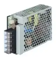
PDA50F-5-N
AC/DC Enclosed Power Supply (PSU), ITE, 1 Outputs, 50 W, 5 V, 10 A
⚠️ Reference pricing provided. In case of supply shortages, we will connect you with our trusted procurement partners to ensure your project's continuity.
- Manufacturer: COSEL
- Product type: AC / DC Enclosed Power Supplies
- SVHC: Lead (04-Feb-2026)
- Product Range: PDA Series
- No. of Outputs: 1Outputs
- Output Power Max: 50W
- Current, Output 4: -
- Input Voltage VAC: 85V AC to 264V AC
- Power Supply Output Type: Fixed
- Output Current - Output 1: 10A
- Output Current - Output 2: -
- Output Current - Output 3: -
- Output Voltage - Output 1: 5V
- Output Voltage - Output 2: -
- Output Voltage - Output 3: -
- Output Voltage - Output 4: -
- Power Supply Applications: ITE
| Delivery and price | |
|---|---|
| Units per pack | 50 |
| Price | 32.17 € |
| Current stock | 10+ |
| Lead time | 30 days |
Datasheet

**AC-DC Power Supplies Enclosed Type**

World wide Safety EMI Inrush OCP OVP Approvals current limiting

## **PDA-series**

## **Feature**

High efficiency Low noise Complies with SEMI F47 Harmonic attenuator (Complies with IEC61000-3-2) Universal input (85-264VAC)

Built-in inrush current, overcurrent and overvoltage protection circuits

## **Safety agency approvals**

UL62368-1, C-UL (equivalent to CAN/CSA-C22.2 No.62368-1), EN62368-1 Complies with DEN-AN

## **5-year warranty (refer to Instruction Manual)**

## **CE marking**

Low Voltage Directive RoHS Directive

## **UKCA marking**

Electrical Equipment Safety Regulations RoHS Regulations

## **EMI**

Complies with CISPR11-B, CISPR32-B, EN55011-B, EN55032-B, FCC Part 15-B, FCC Part 18-B, VCCI-B

**EMS Compliance** : EN61204-3, EN61000-6-2

EN61000-4-2 EN61000-4-3 EN61000-4-4 EN61000-4-5 EN61000-4-6 EN61000-4-8 EN61000-4-11

**PDA-1**

www.cosel.co.jp/en/

February 07, 2024

**AC-DC Power Supplies Enclosed Type**

**PD A 15 F** O O

**==> picture [87 x 8] intentionally omitted <==**

**----- Start of picture text -----**<br>
Ordering information<br>**----- End of picture text -----**<br>


## **PDA15F**

1 2 3 4 5 6

## e R UK cus (D)C ~~€~~ CA

**==> picture [80 x 100] intentionally omitted <==**

**----- Start of picture text -----**<br>
Example recommended EMI/EMC filter<br>NAC-06-472<br>|<br>Ss<br>a<br>=<br>High voltage pulse noise type : NAP series<br>Low leakage current type : NAM series<br>*A higher current rating EMI/EMC filter<br>may be recommended in view of the<br>other devices that could be connected<br>in parallel with the power supply.<br>**----- End of picture text -----**<br>


**==> picture [54 x 50] intentionally omitted <==**

**----- Start of picture text -----**<br>
1Series name<br>2Single output<br>3Output wattage<br>4Universal input<br>5Output voltage<br>6Optional  [*][1]<br>N : with cover<br>**----- End of picture text -----**<br>


For option details, refer to Instruction Manual 6.

||**MODEL**<br>~~a~~|**MODEL**<br>~~a~~|**PDA15F-5**|**PDA15F-12**|**PDA15F-24**|
|---|---|---|---|---|---|
|**INPUT**|**VOLTAGE[VAC]**<br>*2 <br>~~Po~~||85 - 264 1f(Refer to “Derating” and Instruction Manual 1.1)|||
||**CURRENT[A]**<br>~~Po~~<br>~~——~~|**ACIN 100V**<br>~~Po~~<br>~~——~~|0.35typ|||
|||**ACIN 230V**<br>~~——~~<br>~~|~~|0.19typ|||
||**FREQUENCY[Hz]**<br>~~——~~<br>~~|~~<br>~~Po~~<br>~~a~~||50 / 60(45 - 440)<br>~~es~~<br>~~ee~~|||
||**EFFICIENCY[%]**<br>~~Po~~<br>~~ee~~|**ACIN 100V**<br>~~Po~~<br>~~ee~~<br>~~a~~|75.0typ<br>~~ee~~<br>~~es~~|78.5typ<br>~~ee~~<br>~~ee~~|81.0typ<br>~~ee~~|
|||**ACIN 230V**<br>~~ee~~<br>~~a~~|78.5typ<br>~~ee~~<br>~~es~~|81.5typ<br>~~ee~~<br>~~ee~~|83.5typ<br>~~ee~~|
||**INRUSH CURRENT[A]**<br>~~Po~~|**ACIN 100V**<br>~~a~~<br>~~Po~~|15typ (Io=100%)<br>~~es~~<br>~~ee~~|||
|||**ACIN 230V**<br>~~Po~~<br>~~||~~|35typ (Io=100%)|||
||**LEAKAGE CURRENT[mA]**<br>~~Po~~||0.15 / 0.30max(ACIN 100V / 240V,60Hz,Io=100%,Accordingto IEC62368-1,and DEN-AN)|||
|**OUTPUT**|**VOLTAGE[V]**<br>~~a~~||5|12|24|
||**CURRENT[A]**<br>*2 <br>~~a~~||3.0|1.3|0.7|
||**LINE REGULATION[mV]**<br>*3 <br>~~a~~||20max<br>~~GO~~|48max<br>~~GO~~|96max|
||**LOAD REGULATION[mV]**<br>*3 <br>~~GC~~||40max<br>~~GC~~|100max<br>~~GC~~|150max|
||**RIPPLE[mVp-p]**<br>*4|**0 to +55**C <br>~~a~~|80max|120max|120max|
|||**-20 to 0**C<br>~~a a~~|140max<br>~~a~~|160max|160max|
|||**Io=0 to 15%** <br>~~a~~|300max|300max|300max|
||**RIPPLE NOISE[mVp-p]**<br>*4<br>~~Ne~~|**0 to +55**C <br>~~a a~~|120max<br>~~a~~|150max|150max|
|||**-20 to 0**C<br>~~a~~|160max|180max|180max|
|||**Io=0 to 15%** <br>~~a~~<br>~~ee~~<br>~~a~~|360max<br>~~a~~<br>~~es~~|360max<br>~~es~~<br>~~ee~~|360max<br>~~ee~~|
||**TEMPERATURE REGULATION[mV]**<br>~~Ne~~|**0 to +55**C <br><br>~~ee~~<br>~~a~~|50max<br>~~a~~<br>~~es~~|120max<br>~~es~~<br>~~ee~~|240max<br>~~ee~~|
|||**-20 to +55**C <br><br>~~ee~~<br>~~a~~|60max<br>~~a~~<br>~~es~~|150max<br>~~es~~<br>~~ee~~|290max<br>~~ee~~|
||**DRIFT[mV]**<br>*5 <br><br>~~Ne ee~~<br>~~a~~<br>~~RQ~~||20max<br>~~a~~<br>~~es~~<br>~~RQ~~|48max<br>~~es~~<br>~~ee~~<br>~~RQ~~|96max<br>~~ee~~|
||**START-UP TIME[ms]**<br>~~Po~~||80typ (ACIN 100V,Io=100%)|||
||**HOLD-UP TIME[ms]**<br>~~Po~~||20typ (ACIN 100V,Io=100%)/ 150typ (ACIN 230V,Io=100%)|||
||**OUTPUT VOLTAGE ADJUSTMENT RANGE[V]**<br>~~GC~~||4.50 to 5.50<br>~~GC~~|10.0 to 13.2<br>~~GC~~|19.2 to 27.0|
||**OUTPUT VOLTAGE SETTING[V]**<br>~~a~~||5.00 to 5.15|12.00 to 12.48|24.00 to 24.96|
|**PROTECTION**<br>**CIRCUIT AND**<br>**OTHERS**<br>~~RR~~|**OVERCURRENT PROTECTION**<br>~~Po~~<br>~~RR~~||Works over 105% of ratingand recovers automatically|||
||**OVERVOLTAGE PROTECTION**<br>~~RR~~||5.75 to 7.00|15.0 to 18.0|30.0 to 37.0|
||**REMOTE SENSING**<br>~~RR~~<br>~~Po~~||Notprovided|||
|**ISOLATION**|**INPUT-OUTPUT**<br>~~Po~~||AC3,000V 1minute,Cutoff current = 10mA,DC500V 100MWmin(At Room Temperature)|||
||**INPUT-FG**<br>~~Po~~||AC2,000V 1minute,Cutoff current = 10mA,DC500V 100MWmin(At Room Temperature)|||
||**OUTPUT-FG**<br>~~Po~~||AC500V 1minute,Cutoff current = 25mA,DC500V 100MWmin(At Room Temperature)|||
|**ENVIRONMENT**|**OPERATING TEMP.,HUMID.AND ALTITUDE** *2 <br>~~Po~~||-20 to +70C,20 - 90%RH(Non condensing),5,000m (16,500feet)max|||
||**STORAGE TEMP.,HUMID.AND ALTITUDE**<br>~~Po~~||-20 to +75C,20 - 90%RH(Non condensing),9,000m(30,000feet)max|||
||**VIBRATION**<br>~~Po~~||10 - 55Hz,19.6m/s2 (2G),3minutesperiod,60minutes each alongX,Y and Z axis|||
||**IMPACT**<br>~~Po~~||196.1m/s2 (20G),11ms,once each X,Y and Z axis|||
|**SAFETY AND**<br>**NOISE**<br>**REGULATIONS**|**AGENCY APPROVALS**<br>~~Po~~||UL62368-1,C-UL(equivalent to CAN/CSA-C22.2No.62368-1),EN62368-1,Complies with DEN-AN|||
||**CONDUCTED NOISE**<br>~~Po~~||Complies with CISPR11-B,CISPR32-B,EN55011-B,EN55032-B,FCC Part15-B,FCC Part18-B,VCCI-B|||
||**HARMONIC ATTENUATOR** *6 <br>~~Po~~||Complies with IEC61000-3-2(Class A) (No built-inpower factor correction)|||
|**OTHERS**|**CASE SIZE/WEIGHT**<br>~~Po~~||31X78X85mm[1.22X3.07X3.35 inches] (without terminal block) (WXHXD)/ 180gmax(with cover : 210gmax)|||
||**COOLING METHOD**<br>*2 <br>~~Po~~||Convection/Forced air(Requires external fan) (Refer to “Derating”)|||


- *1 The listed options may affect the published standard specifications. Please contact us for detailed product specifications.

- *2 Derating is required.Please contact us for DC input.

- *3 At low load conditions, the burst mode operation will start.  To check load regulation, you will need to measure the characteristics at average mode with instruments.

- *4 This is the value that measured on measuring board with capacitor of 22mF at 150mm from output terminal.

- *5 Drift is the change in DC output for an eight hour period after a half-hour warm-up at 25C, with the input voltage held constant at the rated input/output.

- *6

   - Please contact us about another class. When two or more units are operating it may not comply with the IEC61000-3-2. Please contact us for details.

   - To meet the specification, do not operate overload condition.

-

-

   - Parallel operation is not possible.

-

   - Sound noise may be generated by power supply in case of pulse load.

- Measured by 20MHz oscilloscope or Ripple-Noise meter

- (Equivalent to KEISOKU-GIKEN:RM104).

- Ripple and ripple noise spec is change at Io=0 to 15% by burst operation.

**PDA-2**

www.cosel.co.jp/en/

February 07, 2024

**PDA15F**

## **Block diagram**

**==> picture [462 x 235] intentionally omitted <==**

**----- Start of picture text -----**<br>
FUSE<br>AC250V<br>1.25A INRUSH RECTIFIER<br>AC IN CURRENT NOISE AND<br>85 - 264VAC LIMIT FILTER FILTER<br>FG<br>TRANSFORMER<br>RECTIFIER<br>CONTROL INVERTER AND DC OUT<br>FILTER<br>CURRENT<br>SENSING<br>Photocoupler<br>CONTROL<br>Photocoupler<br>OVER VOLTAGE<br>PROTECTION<br>**----- End of picture text -----**<br>


## **External view**

**==> picture [398 x 289] intentionally omitted <==**

**----- Start of picture text -----**<br>
Output voltage<br>potentiometeradjustment 12.2±1.5 Cover name plate 16.5±2 Point  2 85<br>[0.48] [0.65] [3.35]<br>M3<br>+V Cover (option)<br>-V<br>FG<br>AC(L)<br>AC(N)<br>15.1±1.5 Terminal 31±0.5 36.5<br>[0.59] Cover 2×M3 [1.22] [1.44] Point  1<br>22.6±1.5 Mounting Hole<br>[0.89]<br>2×M3<br>Mounting Hole Name plate<br>*  Tolerance : ±1 [±0.04]<br>*  Weight : 180g max (with cover : 210g max)<br>*  PCB Material / thickness : CEM3 / 1.6mm [0.06]<br>*  Chassis material : Galvanized steel plate<br>*  Dimensions in mm, [  ]= inches<br>*  Mounting torque : 0.6N ・ m max<br>*  Screw tightening torque : M3 0.8N ・ m max<br>*  Please connect safety ground to the unit in 2-M3 holes<br>*  Point  1 , Point  2  are thermometry points. Please refer to Instruction Manual 3.<br>60±0.5 5<br>[2.36] [0.2]<br>7.5 [0.3] 78<br>[3.07]<br>70.5 [2.78]<br>9.5 [0.37] 34.5 [1.36]<br>11.5 [0.45]<br>31 [1.22] 34.5 [1.36]<br>18<br>[0.71]<br>**----- End of picture text -----**<br>


**PDA-3**

www.cosel.co.jp/en/

February 07, 2024

**AC-DC Power Supplies Enclosed Type PDA30F** ~~|~~

**Ordering information**

**PD A 30 F** O O 1 2 3 4 5 6

## R Ais (D)C ~~E~~ EK

**==> picture [140 x 103] intentionally omitted <==**

**----- Start of picture text -----**<br>
1Series name<br>Example recommended EMI/EMC filter<br>NAC-06-472 2Single output<br>3Output wattage<br>|<br>4Universal input<br>5Output voltage<br>Ae 6Optional  [*][1]<br> N : with cover<br>F<br>&<br>High voltage pulse noise type : NAP series<br>Low leakage current type : NAM series<br>*A higher current rating EMI/EMC filter<br>may be recommended in view of the<br>other devices that could be connected<br>in parallel with the power supply.<br>**----- End of picture text -----**<br>


For option details, refer to Instruction Manual 6.

||**MODEL**<br>~~a~~|**MODEL**<br>~~a~~|**PDA30F-5**<br>~~a~~|**PDA30F-12**<br>~~a~~|**PDA30F-24**|
|---|---|---|---|---|---|
|**INPUT**|**VOLTAGE[VAC]**<br>*2 <br>~~-~~||85 - 264 1f(Refer to “Derating” and Instruction Manual 1.1)<br>~~-~~|||
||**CURRENT[A]**<br>~~-~~<br>~~PE~~|**ACIN 100V**<br>~~-~~<br>~~PE~~|0.62typ<br>~~-~~|||
|||**ACIN 230V**<br>~~PE~~<br>~~—~~|0.32typ|||
||**FREQUENCY[Hz]**<br>~~PE~~<br>~~—~~<br>~~OT~~||50 / 60(45 - 440)|||
||**EFFICIENCY[%]**<br>~~OT~~<br>~~—_—_———~~<br>~~po~~|**ACIN 100V**<br>~~OT~~<br>~~—_—_———~~<br>~~po~~|83.0typ<br>~~—_—_———~~|82.0typ<br>~~—_—_———~~<br>~~oT~~|83.5typ|
|||**ACIN 230V**<br>~~—_—_———~~<br>~~po~~|87.0typ<br>~~—_—_———~~|85.5typ<br>~~—_—_———~~<br>~~oT~~|86.5typ|
||**INRUSH CURRENT[A]**<br>~~po~~<br>~~PE~~|**ACIN 100V**<br>~~po~~<br>~~PE~~|15typ (Io=100%)<br>~~oT~~|||
|||**ACIN 230V**<br>~~PE~~<br>~~ES~~|35typ (Io=100%)|||
||**LEAKAGE CURRENT[mA]**<br>~~|~~||0.25 / 0.55 max(ACIN 100V / 240V,60Hz,Io=100%,Accordingto IEC62368-1,and DEN-AN)<br>~~|~~|||
|**OUTPUT**|**VOLTAGE[V]**<br>~~a~~||5<br>~~a~~|12<br>~~a~~|24|
||**CURRENT[A]**<br>*2 <br>~~a~~||6.0<br>~~a~~|2.5<br>~~a~~|1.3|
||**LINE REGULATION[mV]**<br>*3 <br>~~a~~||20max<br>~~a~~|48max<br>~~a~~|96max|
||**LOAD REGULATION[mV]**<br>*3 <br>~~a~~<br>~~EE——~~||40max<br>~~a~~<br>~~——~~|100max<br>~~a~~|150max|
||**RIPPLE[mVp-p]**<br>*4<br>~~EE~~<br>~~EE~~|**0 to +55**C <br>~~E——~~|80max<br>~~——~~|120max|120max|
|||**-20 to 0**C<br>~~E——~~<br>~~a~~|140max<br>~~——~~|160max|160max|
|||**Io=0 to 15%** <br>~~E——~~<br>~~a~~<br>~~E——~~|300max<br>~~——~~<br>~~——~~|300max|300max|
||**RIPPLE NOISE[mVp-p]**<br>*4<br>~~EE~~<br>~~EE~~<br>~~re~~|**0 to +55**C <br>~~E——~~<br>~~E——~~|120max<br>~~——~~<br>~~——~~|150max|150max|
|||**-20 to 0**C<br>~~E——~~<br>~~a~~|160max<br>~~——~~|180max|180max|
|||**Io=0 to 15%** <br>~~E——~~<br>~~a~~<br>~~re~~|360max<br>~~——~~<br>~~eee~~|360max<br>~~eee~~|360max|
||**TEMPERATURE REGULATION[mV]**<br>~~EE~~<br>~~re~~|**0 to +55**C <br>~~E——~~<br>~~re~~|50max<br>~~——~~<br>~~eee~~|120max<br>~~eee~~|240max|
|||**-20 to +55**C <br>~~re~~<br>~~a~~|60max<br>~~eee~~<br>~~a~~|150max<br>~~eee~~|290max|
||**DRIFT[mV]**<br>*5 <br>~~re~~<br>~~a~~||20max<br>~~eee~~|48max<br>~~eee~~|96max|
||**START-UP TIME[ms]**||80typ (ACIN 100V,Io=100%)|||
||**HOLD-UP TIME[ms]**||20typ (ACIN 100V,Io=100%)/ 150typ (ACIN 230V,Io=100%)|||
||**OUTPUT VOLTAGE ADJUSTMENT RANGE[V]**<br>~~a~~||4.50 to 5.50|10.0 to 13.2|20.4 to 27.0|
||**OUTPUT VOLTAGE SETTING[V]**<br>~~eee~~||5.00 to 5.15<br>~~eee~~|12.00 to 12.48<br>~~eee~~|24.00 to 24.96|
|**PROTECTION**<br>**CIRCUIT AND**<br>**OTHERS**<br>~~—~~|**OVERCURRENT PROTECTION**||Works over 105% of ratingand recovers automatically|||
||**OVERVOLTAGE PROTECTION**<br>~~a~~||5.75 to 7.00|15.0 to 18.0|30.0 to 37.0|
||**REMOTE SENSING**<br>~~|~~<br>~~—~~||Notprovided|||
|**ISOLATION**<br>~~——~~|**INPUT-OUTPUT**<br>~~——~~||AC3,000V 1minute,Cutoff current = 10mA,DC500V 100MWmin(At Room Temperature)|||
||**INPUT-FG**<br>~~——~~||AC2,000V 1minute,Cutoff current = 10mA,DC500V 100MWmin(At Room Temperature)|||
||**OUTPUT-FG**<br>~~—|~~||AC500V 1minute,Cutoff current = 25mA,DC500V 100MWmin(At Room Temperature)|||
|**ENVIRONMENT**<br>~~——~~|**OPERATING TEMP.,HUMID.AND ALTITUDE** *2 <br>~~—~~<br>~~—~~||-20 to +70C,20 - 90%RH(Non condensing),5,000m (16,500feet)max|||
||**STORAGE TEMP.,HUMID.AND ALTITUDE**<br>~~——~~||-20 to +75C,20 - 90%RH(Non condensing),9,000m(30,000feet)max|||
||**VIBRATION**<br>~~——~~||10 - 55Hz,19.6m/s2 (2G),3minutesperiod,60minutes each alongX,Y and Z axis|||
||**IMPACT**<br>~~—|~~||196.1m/s2 (20G),11ms,once each X,Y and Z axis|||
|**SAFETY AND**<br>**NOISE**<br>**REGULATIONS**|**AGENCY APPROVALS**<br>~~CL~~||UL62368-1,C-UL(equivalent to CAN/CSA-C22.2No.62368-1),EN62368-1,Complies with DEN-AN|||
||**CONDUCTED NOISE**<br>~~ES~~||Complies with CISPR11-B,CISPR32-B,EN55011-B,EN55032-B,FCC Part15-B,FCC Part18-B,VCCI-B|||
||**HARMONIC ATTENUATOR** *6 <br>~~|~~||Complies with IEC61000-3-2(Class A) (No built-inpower factor correction)|||
|**OTHERS**|**CASE SIZE/WEIGHT**||31X78X103mm[1.22X3.07X4.06 inches] (without terminal block) (WXHXD)/ 250gmax(with cover : 280gmax)|||
||**COOLING METHOD**<br>*2 <br>~~Es~~||Convection/Forced air(Requires external fan) (Refer to “Derating”)|||


- *1 The listed options may affect the published standard specifications. Please contact us for detailed product specifications.

- *2 Derating is required.Please contact us for DC input.

- *3 At low load conditions, the burst mode operation will start.  To check load regulation, you will need to measure the characteristics at average mode with instruments.

- *4 This is the value that measured on measuring board with capacitor of 22mF at 150mm from output terminal.

- *5 Drift is the change in DC output for an eight hour period after a half-hour warm-up at 25C, with the input voltage held constant at the rated input/output.

- *6

   - Please contact us about another class. When two or more units are operating it may not comply with the IEC61000-3-2. Please contact us for details.

   - To meet the specification, do not operate overload condition.

-

-

   - Parallel operation is not possible.

-

   - Sound noise may be generated by power supply in case of pulse load.

- Measured by 20MHz oscilloscope or Ripple-Noise meter

- (Equivalent to KEISOKU-GIKEN:RM104).

- Ripple and ripple noise spec is change at Io=0 to 15% by burst operation.

**PDA-4**

www.cosel.co.jp/en/

February 07, 2024

**PDA30F**

## **Block diagram**

**==> picture [462 x 236] intentionally omitted <==**

**----- Start of picture text -----**<br>
FUSE<br>AC250V<br>2.5A INRUSH RECTIFIER<br>AC IN CURRENT NOISE AND<br>85 - 264VAC LIMIT FILTER FILTER<br>FG<br>TRANSFORMER<br>RECTIFIER<br>CONTROL INVERTER AND DC OUT<br>FILTER<br>CURRENT<br>SENSING<br>Photocoupler<br>CONTROL<br>Photocoupler<br>OVER VOLTAGE<br>PROTECTION<br>**----- End of picture text -----**<br>


## **External view**

**==> picture [426 x 276] intentionally omitted <==**

**----- Start of picture text -----**<br>
Output voltage<br>potentiometeradjustment 12.2±1.5 16.5±2 Point  2 103<br>[0.48] Cover name plate [0.65] [4.06]<br>M3<br>+V<br>Cover (option)<br>-V<br>FG<br>AC(L)<br>AC(N)<br>Terminal<br>15.1±1.5 Cover 46±0.5 40.5<br>[0.59] [1.81] [1.59]<br>22.6[0.89]±1.5 2×M3 Point  1<br>Mounting Hole<br>2×M3<br>Mounting Hole Name plate<br>*  Tolerance : ±1 [±0.04]<br>*  Weight : 250g max (with cover : 280g max)<br>*  PCB Material / thickness : CEM3 / 1.6mm [0.06]<br>*  Chassis material : Galvanized steel plate<br>*  Dimensions in mm, [  ]= inches<br>*  Mounting torque : 0.6N ・ m max<br>*  Screw tightening torque : M3 0.8N ・ m max<br>*  Please connect safety ground to the unit in 2-M3 holes<br>*  Point  1 , Point  2  are thermometry points. Please refer to Instruction Manual 3. 75±0.5 8.5<br>[2.95] [0.33]<br>05. 7.5 [0.3] 78 [3.07]<br>7 [2.78]<br>9.5 [0.37] 36.5 [1.44]<br>11.5 [0.45]<br>31 [1.22] 34.5 [1.36]<br>18<br>[0.71]<br>**----- End of picture text -----**<br>


**PDA-5**

www.cosel.co.jp/en/

February 07, 2024

**AC-DC Power Supplies Enclosed Type Ordering information - - PD A 50 F** O O **PDA50F** 1 2 3 4 5 6 ~~Ye —~~ 1Series nameSeries name R **Example recommended EMI/EMC filterNAC-06-472NAC-06-472** 2Single outputSingle output 3Output wattageOutput wattage 4Universal inputUniversal input 5Output voltageOutput voltage We OC ~~e~~ w | —¥

**==> picture [140 x 103] intentionally omitted <==**

**----- Start of picture text -----**<br>
1Series nameSeries name<br>Example recommended EMI/EMC filterNAC-06-472NAC-06-472 2Single outputSingle output<br>3Output wattageOutput wattage<br>4Universal inputUniversal input<br>5Output voltageOutput voltage<br>| —¥<br>6Optional  [*][1]<br>N : with cover<br>High voltage pulse noise type : NAP series<br>Low leakage current type : NAM series<br>*A higher current rating EMI/EMC filter<br>may be recommended in view of the<br>other devices that could be connected<br>in parallel with the power supply.<br>**----- End of picture text -----**<br>


For option details, refer to Instruction Manual 6.

||**MODEL**<br>~~Pd~~|**MODEL**<br>~~Pd~~|**PDA50F-5**<br>~~Pd~~|**PDA50F-12**<br>~~Pd~~|**PDA50F-24**|
|---|---|---|---|---|---|
|**INPUT**|**VOLTAGE[VAC]**<br>*2 <br>~~Po~~||85 - 264 1f(Refer to Instruction Manual 1.1)|||
||**CURRENT[A]**<br>~~Po~~<br>~~=~~|**ACIN 100V**<br>~~Po~~<br>~~=~~|1.05typ|||
|||**ACIN 230V**<br>~~=~~<br>~~—~~|0.52typ|||
||**FREQUENCY[Hz]**<br>~~=~~<br>~~—~~<br>~~ot~~<br>~~——————~~||50 / 60(45 - 440)<br>~~——————~~<br>~~ee~~|||
||**EFFICIENCY[%]**<br>~~ot~~<br>~~——————~~|**ACIN 100V**<br>~~ot~~<br>~~——————~~|81.5typ<br>~~——————~~|82.5typ<br>~~ee~~|85.0typ|
|||**ACIN 230V**<br>~~——————~~<br>~~a~~|85.0typ<br>~~——————~~|85.0typ<br>~~ee~~|87.5typ|
||**INRUSH CURRENT[A]**<br>~~——————~~<br>~~PF~~<br>~~|~~|**ACIN 100V**<br>~~——————~~<br>~~PF~~<br>~~|~~|15typ (Io=100%)<br>~~——————~~<br>~~ee~~|||
|||**ACIN 230V**<br>~~PF~~<br>~~|~~|35typ (Io=100%)|||
||**LEAKAGE CURRENT[mA]**<br>~~|~~<br>~~Po~~||0.3 / 0.65 max(ACIN 100V / 240V,60Hz,Io=100%,Accordingto IEC62368-1,and DEN-AN)|||
|**OUTPUT**|**VOLTAGE[V]**<br>~~a~~||5<br>~~a~~<br>~~a~~|12<br>~~a~~|24|
||**CURRENT[A]**<br>*2 <br>~~a~~||10<br>~~a~~|4.3|2.2|
||**LINE REGULATION[mV]**<br>*3 <br>~~a~~||20max<br>~~a~~|48max|96max|
||**LOAD REGULATION[mV]**<br>*3 <br>~~a~~<br>~~SE~~||40max<br>~~a~~<br>~~——————_—_~~|100max<br>~~——————_—_~~|150max|
||**RIPPLE[mVp-p]**<br>*4<br>~~SE~~|**0 to +50**C <br>~~E~~|80max<br>~~——————_—_~~|120max<br>~~——————_—_~~|120max|
|||**-20 to 0**C<br>~~E~~<br>~~a~~|140max<br>~~——————_—_~~|160max<br>~~——————_—_~~|160max|
|||**Io=0 to 15%** <br>~~E~~<br>~~a~~|300max<br>~~——————_—_~~<br>~~De~~|300max<br>~~——————_—_~~<br>~~De~~|300max|
||**RIPPLE NOISE[mVp-p]**<br>*4<br>~~SE~~<br>~~a~~|**0 to +50**C <br>~~E~~<br>~~a~~|120max<br>~~——————_—_~~<br>~~a~~|150max<br>~~——————_—_~~<br>~~a~~|150max|
|||**-20 to 0**C<br>~~a~~<br>~~a~~|160max<br>~~a~~<br>~~ae~~|180max<br>~~a~~<br>~~ae~~|180max|
|||**Io=0 to 15%** <br>~~a~~<br>~~a~~|360max<br>~~a~~<br>~~Le~~|360max<br>~~a~~<br>~~Le~~|360max|
||**TEMPERATURE REGULATION[mV]**<br>~~a~~|**0 to +50**C <br>~~a~~|50max|120max|240max|
|||**-20 to +50**C <br>~~a~~<br>~~a~~|60max|150max|290max|
||**DRIFT[mV]**<br>*5 <br>~~a~~||20max|48max|96max|
||**START-UP TIME[ms]**<br>~~po~~||80typ (ACIN 100V,Io=100%)|||
||**HOLD-UP TIME[ms]**<br>~~po~~||20typ (ACIN 100V,Io=100%)/ 140typ (ACIN 230V,Io=100%)|||
||**OUTPUT VOLTAGE ADJUSTMENT RANGE[V]**<br>~~a~~||4.00 to 5.50|10.0 to 13.2|19.2 to 27.0|
||**OUTPUT VOLTAGE SETTING[V]**<br>~~a ~~||5.00 to 5.15<br> ~~a~~|12.00 to 12.48|24.00 to 24.96|
|**PROTECTION**<br>**CIRCUIT AND**<br>**OTHERS**|**OVERCURRENT PROTECTION**<br>~~Po~~||Works over 105% of ratingand recovers automatically|||
||**OVERVOLTAGE PROTECTION**<br>~~a~~||5.75 to 7.00|15.0 to 18.0|30.0 to 37.0|
||**REMOTE SENSING**<br>~~Po~~||Notprovided|||
|**ISOLATION**|**INPUT-OUTPUT**<br>~~Po~~||AC3,000V 1minute,Cutoff current = 10mA,DC500V 100MWmin(At Room Temperature)|||
||**INPUT-FG**<br>~~Po~~||AC2,000V 1minute,Cutoff current = 10mA,DC500V 100MWmin(At Room Temperature)|||
||**OUTPUT-FG**<br>~~Po~~||AC500V 1minute,Cutoff current = 25mA,DC500V 100MWmin(At Room Temperature)|||
|**ENVIRONMENT**|**OPERATING TEMP.,HUMID.AND ALTITUDE** *2 <br>~~Po~~||-20 to +70C,20 - 90%RH(Non condensing),5,000m (16,500feet)max|||
||**STORAGE TEMP.,HUMID.AND ALTITUDE**<br>~~Po~~||-20 to +75C,20 - 90%RH(Non condensing),9,000m(30,000feet)max|||
||**VIBRATION**<br>~~Po~~||10 - 55Hz,19.6m/s2 (2G),3minutesperiod,60minutes each alongX,Y and Z axis|||
||**IMPACT**<br>~~Po~~||196.1m/s2 (20G),11ms,once each X,Y and Z axis|||
|**SAFETY AND**<br>**NOISE**<br>**REGULATIONS**|**AGENCY APPROVALS**<br>~~Po~~||UL62368-1,C-UL(equivalent to CAN/CSA-C22.2No.62368-1),EN62368-1,Complies with DEN-AN|||
||**CONDUCTED NOISE**<br>~~po~~||Complies with CISPR11-B,CISPR32-B,EN55011-B,EN55032-B,FCC Part15-B,FCC Part18-B,VCCI-B|||
||**HARMONIC ATTENUATOR** *6 <br>~~Po~~||Complies with IEC61000-3-2(Class A) (No built-inpower factor correction)|||
|**OTHERS**|**CASE SIZE/WEIGHT**<br>~~Po~~||31X82X120mm[1.22X3.23X4.72 inches] (without terminal block) (WXHXD)/ 330gmax(with cover : 370gmax)|||
||**COOLING METHOD**<br>*2 <br>~~Po~~||Convection/Forced air(Requires external fan) (Refer to “Derating”)|||


- *1 The listed options may affect the published standard specifications. Please contact us for detailed product specifications.

- *2 Derating is required.Please contact us for DC input.

- *3 At low load conditions, the burst mode operation will start.  To check load regulation, you will need to measure the characteristics at average mode with instruments.

- *4 This is the value that measured on measuring board with capacitor of 22mF at 150mm from output terminal.

- *5 Drift is the change in DC output for an eight hour period after a half-hour warm-up at 25C, with the input voltage held constant at the rated input/output.

- *6

   - Please contact us about another class. When two or more units are operating it may not comply with the IEC61000-3-2. Please contact us for details.

   - To meet the specification, do not operate overload condition.

-

-

   - Parallel operation is not possible.

-

   - Sound noise may be generated by power supply in case of pulse load.

- Measured by 20MHz oscilloscope or Ripple-Noise meter

- (Equivalent to KEISOKU-GIKEN:RM104).

- Ripple and ripple noise spec is change at Io=0 to 15% by burst operation.

**PDA-6**

www.cosel.co.jp/en/

February 07, 2024

**PDA50F**

## **Block diagram**

**==> picture [462 x 236] intentionally omitted <==**

**----- Start of picture text -----**<br>
FUSE<br>AC250V<br>2.5A INRUSH RECTIFIER<br>AC IN CURRENT NOISE AND<br>85 - 264VAC LIMIT FILTER FILTER<br>FG<br>TRANSFORMER<br>RECTIFIER<br>CONTROL INVERTER AND DC OUT<br>FILTER<br>CURRENT<br>SENSING<br>Photocoupler<br>CONTROL<br>Photocoupler<br>OVER VOLTAGE<br>PROTECTION<br>**----- End of picture text -----**<br>


## **External view**

**==> picture [446 x 258] intentionally omitted <==**

**----- Start of picture text -----**<br>
Output voltage<br>adjustment 11.2±1.5 16.5±2 120<br>potentiometer [0.44] [0.65] [4.72]<br>Cover name plate<br>M3<br>+V Cover (option)<br>-V<br>FG<br>2×M3<br>AC(L) Mounting Hole<br>AC(N)<br>14.1±1.5 77±0.5 4<br>[0.56] Terminal [3.03] [0.16]<br>21.6[0.85]±1.5 Cover Point  2 2×M3 Point  1<br>Mounting Hole Name plate<br>*  Tolerance : ±1 [±0.04]<br>*  Weight : 330g max (with cover : 370g max)<br>*  PCB Material / thickness : CEM3 / 1.6mm [0.06]<br>*  Chassis material : Galvanized steel plate<br>*  Dimensions in mm, [  ]= inches<br>*  Mounting torque : 0.6N ・ m max<br>*  Screw tightening torque : M3 0.8N ・ m max<br>*  Please connect safety ground to the unit in 2-M3 holes 88±0.5 11<br>*  Point  1 , Point  2  are thermometry points. Please refer to Instruction Manual 3. [3.46]<br>0.6 [0.02]<br>7.5 [0.3] 82 [3.23]<br>70.5 [2.78]<br>9.5 [0.37] 35 [1.38]<br>11.5 [0.45]<br>31 [1.22] 34.5 [1.36]<br>18<br>[0.71]<br>**----- End of picture text -----**<br>


**PDA-7**

www.cosel.co.jp/en/

February 07, 2024

## **PDA-series**

## **Assembling and Installation Method**

## Installation method

- ¡ For the metal chassis, keep the distance d1 for isolation between component and metal chassis.

- The d1 dimension is the distance required for insulation and does not satisfy cooling conditions. For cooling conditions, please refer to “Derating” and section 3 of the instruction manual.

- ¡ Do not insert a screw more than 6mm from the outside of a power supply to keep enough insulation distance between the screw and internal components.

- ¡ If you use two or more power supplies side by side, please keep a sufficient distance between them to allow enough air ventilation.

- ¡ Ambient temperature around each power supply should not exceed the temperature range shown in “derating”.

**==> picture [204 x 306] intentionally omitted <==**

**----- Start of picture text -----**<br>
d1 d1:3mm min<br>Chassis of<br>Chassis<br>customer system<br>Mounting Screw<br>6mm max<br>A B C<br>Normal mounting<br>**----- End of picture text -----**<br>


## **Derating**

- ¿ Derating curve for input voltage PDA15F, PDA30F

**==> picture [119 x 106] intentionally omitted <==**

**----- Start of picture text -----**<br>
[%]<br>100<br>80<br>85 90<br>AC input voltage [VAC]<br>Load factor<br>**----- End of picture text -----**<br>


## ¿ PDA15F

Ambient temperature derating curve (Reference value)

**==> picture [222 x 109] intentionally omitted <==**

**----- Start of picture text -----**<br>
(1)A mounting (2)A-C mounting<br>(1)B,C mounting<br>100<br>80<br>75<br>60<br>(1)Convection<br>40 (2)Forced air (0.5m [3] / min)<br>20<br>15<br>0<br>-20 -10 0 10 20 30 40 50 55 60 70<br>Ambient temperature [ C ]<br>Load factor [%]<br>**----- End of picture text -----**<br>


## ¿ PDA15F-□-N

Ambient temperature derating curve (Reference value)

**==> picture [221 x 109] intentionally omitted <==**

**----- Start of picture text -----**<br>
(1)A mounting (2)A-C mounting<br>(1)B,C mounting<br>100<br>80<br>75<br>70<br>60<br>50 (1)Convection<br>40 (2)Forced air (0.5m [3] / min)<br>20<br>15<br>0<br>-20 -10 0 10 20 30 40 45 50 60 70<br>Ambient temperature [ C ]<br>Load factor [%]<br>**----- End of picture text -----**<br>


**PDA-8**

www.cosel.co.jp/en/

February 07, 2024

**PDA-series**

## ~~EE~~ **Derating**

¿ PDA30F-□-N Ambient temperature derating curve (Reference value)

¿ PDA30F Ambient temperature derating curve (Reference value)

**==> picture [460 x 432] intentionally omitted <==**

**----- Start of picture text -----**<br>
(1)A mounting (2)A-C mounting (1)A mounting<br>(1)C mounting (1)B mounting (1)C mounting (1)B mounting<br>100 100<br>8075 F/G 807070 F/O<br>60 WM es 60 UE SS<br>(1)Convection 50 (1)Convection<br>40 (2)Forced air (0.5m [3] / min) 40 (2)Forced air (0.5m [[3]] / min)<br>20 MD) To 20 MD) a<br>150 iT 1500 TTT TNT TTT<br>-20 -10 0 10 20 30 40 45 50 55 60 70 -2020 -1010 0 10 20 30 40 50 60 70<br>Ambient temperature [ C ] Ambient temperature [[ C ]<br>  PDA50F-5   ¿   PDA50F-5-N<br>Ambient temperature derating curve   Ambient temperature derating curve<br>(Reference value) (Reference value)<br>(2)A-C mounting<br>(1)B,C mounting (1)A mounting (1)C mounting (1)A,B mounting<br>100 100<br>80 F/R =e 80 9 /SNeSNe<br>6050 TW) (1)Convection SE NNG 6040 F/M (1)Convection(2)Forced air (0.5m NG<br>40 TE (2)Forced air (0.5m [3] / min) NS 40 Wy) (2)Forced air (0.5m [[3]] / min) ™<br>20 MD) TT 20 MD) TT<br>150 i 1500 TAT TNT TTT TTT<br>-20 -10 0 10 20 30 40 45 50 60 70 -2020 -1010 0 10 20 30 35 40 50 60 70<br>Ambient temperature [ C ] Ambient temperature [[ C ]<br>  PDA50F-12, -24  ¿   PDA50F-12-N, -24-N<br>Ambient temperature derating curve   Ambient temperature derating curve<br>(Reference value) (Reference value)<br>(2)A-C mounting (1)C mounting (1)A mounting<br>(1)B,C mounting (1)A mounting (1)B mounting<br>100 100<br>80 P/N 80 P/N<br>6050 TW) (1)Convection EaSNS 6050 Wy) (1)Convection Ne<br>40 (2)Forced air (0.5m [3] / min) 40 (2)Forced air (0.5m [3] / min)<br>30<br>20 20<br>15 15<br>0 TTT NTN TTT 0 i<br>-20 -10 0 10 20 30 40 45 50 60 70 -20 -10 0 10 20 30 40 45 50 60 70<br>Ambient temperature [ C ] Ambient temperature [ C ]<br>Load factor [%] Load factor [%]<br>Load factor [%] Load factor [%]<br>Load factor [%] Load factor [%]<br>**----- End of picture text -----**<br>


**==> picture [224 x 270] intentionally omitted <==**

**----- Start of picture text -----**<br>
(1)A mounting (2)A-C mounting<br>(1)C mounting (1)B mounting<br>100<br>F/O<br>807070<br>60 UE SS<br>50 (1)Convection<br>40 (2)Forced air (0.5m [[3]] / min)<br>20 MD) a<br>1500 TTT TNT TTT<br>-2020 -1010 0 10 20 30 40 50 60 70<br>Ambient temperature [[ C ]<br>  PDA50F-5-N<br>Ambient temperature derating curve<br>(Reference value)<br>(2)A-C mounting<br>(1)C mounting (1)A,B mounting<br>100<br>80 9 /SNeSNe<br>6040 F/M Wy) (1)Convection(2)Forced air (0.5m [[3]] / min) NG ™<br>20 MD) TT<br>1500 TAT TNT TTT TTT<br>-2020 -1010 0 10 20 30 35 40 50 60 70<br>Ambient temperature [[ C ]<br>Load factor [%]<br>Load factor [%]<br>**----- End of picture text -----**<br>


## ¿ PDA50F-5

Ambient temperature derating curve (Reference value)

## ¿ PDA50F-12, -24

Ambient temperature derating curve (Reference value)

(1)C mounting (1)A mounting (2)A-C mounting (1)B mounting

## **Instruction Manuals** ~~—Eo~~ ◆ Please see catalog and instructionmanual before you use. **PDA NOTICE**

Instruction Manuals https://www.cosel.co.jp/redirect/catalog/en/PDA/ Before using our product https://en.cosel.co.jp/technical/caution/index.html

## **Basic Characteristics Data** ~~ee)~~

|Model|Circuit method|Switching<br>frequency<br>[kHz] *1 *2|Input<br>current<br> *3[A]|Inrush<br>current<br>protection|PCB/Pattern|PCB/Pattern|PCB/Pattern|Series/Parallel<br>operation availability|Series/Parallel<br>operation availability|
|---|---|---|---|---|---|---|---|---|---|
||||||Material|Single<br>sided|Double<br>sided|Series<br>operation|Parallel<br>operation|
|PDA15F|Flyback converter|20 to 125|0.35|Thermistor|CEM-3|Yes|-|Yes|No|
|PDA30F|Flyback converter|30 to 130|0.62|Thermistor|CEM-3|Yes|-|Yes|No|
|PDA50F|Flyback converter|25 to 130|1.05|Thermistor|CEM-3|Yes|-|Yes|No|


- *1  The value changes depending on input and load.

- *2  At light load, burst operation is performed to reduce input power. The switching frequency is changed by using condition. Please contact us for more details.

- *3  The value of input current is at ACIN 100V and rated load.

**PDA-9**

www.cosel.co.jp/en/

February 07, 2024
Updated at June 4, 2026
About Novapart
Novapart is a B2B electronic component broker specialising in stock shortages and cost reduction. We source hard-to-find parts and identify compliant alternatives across a catalogue of 410,000+ components from 500+ manufacturers.
Learn more →Stock Shortage Specialist
When a component is unavailable, discontinued or has an unacceptable lead time, we tap into our network of vetted European and Asian distributors to source what you need — without compromising on quality or traceability.
Request a quote →Compliant Alternatives
We identify pin-to-pin, electrically equivalent substitutes that meet the same certifications (RoHS, AEC-Q100, REACH) as your original specification — validated against datasheets, not just part numbers. Often at a lower cost.
BOM Analysis service →