
Image not available
Illustrative purposes only

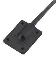
PCUWB01.01.0500G
Patch Antenna, 8GHz to 10.3GHz, 3 VSWR, 4.1dBi Gain, Linear Polarisation, Adhesive
⚠️ Reference pricing provided. In case of supply shortages, we will connect you with our trusted procurement partners to ensure your project's continuity.
- Manufacturer: TAOGLAS
- Product type:
- Antenna Type:Patch; Frequency Min:8GHz; Frequency Max:10.3GHz; Antenna Mounting:Adhesive; Gain:4.1dBi; VSWR:3; Input Power:5W; Input Impedance:50ohm; Antenna Polarisation:Linear; Product
- Gain: 4.1dBi
- SVHC: To Be Advised
- VSWR: 3
- Input Power: 5W
- Antenna Type: Patch
- Frequency Max: 10.3GHz
- Frequency Min: 8GHz
- Product Range: -
- Input Impedance: 50ohm
- Antenna Mounting: Adhesive
- Antenna Polarisation: Linear
| Delivery and price | |
|---|---|
| Units per pack | 100 |
| Price | 14.32 € |
| Current stock | 10+ |
| Lead time | 30 days |
Datasheet

## **Specification**

## **Patent Pending**

Part No. : **PCUWB01.01.0500G**

Description : Ultra-Wide Band Omnidirectional Antenna For 3-5GHz & 6-10GHz

Features : Omnidirectional Radiation Pattern For European and USA UWB Applications In Channels 1-15 Frequency: 3-5GHz & 6-10GHz IP67 Rated Enclosure Adhesive Mount on Plastic Cable: Low Loss 0.5M CFD200 Connector: SMA(M) ST Dims: 36*10*10mm

**RoHS compliant**

SPE-18-8-101/A/AZ         Page **1** of **16**

## **1. Introduction**

The PCUWB.01 is the only external adhesive-mount UWB antenna designed to cover all worldwide UWB frequencies. With excellent efficiency and an omnidirectional radiation pattern, it provides strong, homogeneous coverage in all directions from the sensor. PCUWB.01 also shows excellent fidelity factor numbers and low group delay variation to preserve maximum signal integrity.

Ultra-Wideband (also known as UWB) is a low power digital wireless technology for transmitting large amounts of digital data over a wide spectrum of frequency bands typically spanning more than 500MHz with very low power for short distances.

The low power requirements of UWB mean increased battery life of sensors and tags leading to reduction in overall operational costs. PCUWB.01 is one of several Taoglas-developed antennas designed for seamless integration with the recently launched Decawave ScenSor DW1000 module as well as compatibility with any other UWB sensor modules on the market.

Applications and Uses

- Precision surveying

- Smart home and entertainment systems

- Indoor position location and tracking applications

The PCUWB.01 enclosure is made from IP67 rated PP making it ideal for both indoor and outdoor environments. Cable and connectors for the PCUWB.01 are customizable. Contact your regional Taoglas sales office for support.

SPE-18-8-101/A/AZ         Page **2** of **16**

## **1.1. Applications of Pulsed UWB antenna Technology**

**Radar** -These short-pulsed antennas provide very fine range resolution and precision distance and positioning measurement capabilities. UWB signals enable inexpensive high definition radar antennas which find use in automotive sensors, smart airbags, and precision surveying applications amongst many others.

**Home Network Connectivity** - Smart home and entertainment systems can take advantage of high data rates for streaming high quality audio and video contents in real time for consumer electronics and computing within a home environment.

**Position location & Tracking** - UWB antennas also find use in Position Location and Tracking applications such as locating patients in case of critical condition, hikers injured in remote areas, tracking cars, and managing a variety of goods in a big shopping mall. UWB offers better noise immunity and better accuracy to within a few cm compared to current localization technologies such as Assisted GPS for Indoors, Wi-Fi and cellular which are at best able to offer meter level precision. Tethered Indoor positioning UWB systems that measure the angles of arrival of ultra-wideband (UWB) radio signals perform triangulation by using multiple sensors to communicate with a tag device.

SPE-18-8-101/A/AZ         Page **3** of **16**

## **2. Specification**

|**ELECTRICAL**<br>~~Ld~~<br>~~ee~~|**ELECTRICAL**<br>~~Ld~~<br>~~ee~~|**ELECTRICAL**<br>~~Ld~~<br>~~ee~~|**ELECTRICAL**<br>~~Ld~~<br>~~ee~~|
|---|---|---|---|
|STANDARD<br>~~i~~|USA UWB<br>channels 1-4<br>~~i~~|EU UWB/ USA UWB<br>channels 5-8<br>~~i~~<br>~~ee~~|USA UWB<br>channels 9-15<br>~~i~~|
|Operation Frequency<br>(GHz)|3.1–5.0|6.2–8.0<br>~~ee~~|8.0–10.3|
|Efficiency (%)||||
|0.5 m|>65%|>55%|>39%|
|1 m|>55%|>45%|>30%|
|3m|>35%|>25%|>19%|
|5 m|>27%|>16%|>11%|
|Peak Gain (dBi)||||
|0.5 m|<7.5|<4.1|<4.1|
|1 m|<6.3|<3.9|<3.9|
|3 m|<4.8|<1.2|<2|
|5 m|<3.5|<0|<-1.5|
|Average Gain (dB)||||
|0.5 m|>-1.8|>-2.8|>-4.2|
|1 m|>-2.6|>-3.5|>-4.8|
|3 m|>-4.2|>-6|>-7.6|
|5 m|>-5.8|>-8|>-9.7|
|Return Loss (dB)|<-8|<-4|<-6|
|Max VSWR|>2:1|>3:1|>3:1|
|Radiation Properties|Omnidirectional|||
|Polarization|Linear|||
|Impedance|50 Ω|||
|Max<br>5 W<br>**MECHANICAL**<br>~~—~~||||
|Dimension<br>~~—~~|36*30*10 mm|||
|Casing|PP|||
|Connector|SMA(M) ST, fully customizable|||
|Cable|0.5M CFD200, fully customizable|||
|Waterproof|IP67|||
|Weight|50g|||
|**ENVIRONMENTAL**<br>Operation Temperature<br>-40°C to 85°C<br>~~———E——EEEEooooooooooenn~~||||
|Storage Temperature|-40°C to 85°C|||
|Humidity|Non-condensino 65°C 95% RH|||


SPE-18-8-101/A/AZ         Page **4** of **16**

## **3. Antenna Characteristics**

## **3.1. Return Loss**

## **3.2. VSWR**

SPE-18-8-101/A/AZ         Page **5** of **16**

## **3.3. Efficiency**

## **3.4. Peak Gain**

SPE-18-8-101/A/AZ         Page **6** of **16**

## **3.5. Average Gain**

## **3.6. Antenna Radiation Pattern**

## 3.6.1. Measurement Setup

SPE-18-8-101/A/AZ         Page **7** of **16**

## **3.6.2.** 2D Radiation Pattern (dBi)

## **XY Plane**

## **YZ Plane**

## **XZ Plane**

SPE-18-8-101/A/AZ         Page **8** of **16**

## 3.6.3. 3D Radiation Pattern (dBi)

## **4GHz**

## **6 GHz**

## **9 GHz**

## **7 GHz**

## **10 GHz**

SPE-18-8-101/A/AZ         Page **9** of **16**

## **3.7. Group Delay**

Total system group delay includes the propagation delay in the transmitting antenna (Tx), propagation channel (Ch), and receiving antenna (Rx). Group delay can vary across directions of propagation (theta or phi angles). This group delay variation over theta or phi represents output signal distortions and should be known and minimized if possible.

The measured and normalized group delay value for PCUWB.01 is presented below for 4 principal angles in the YZ plane, measured at 4 GHz and 6.5 GHz (UWB channels 2 and 5). A group delay variation of 100-150 ps is considered excellent for UWB system implementation. The observed group delay variation of 99 ps in channel 2 and 150 ps in channel 5 for PCUWB.01 will provide excellent performance.

The measurements were performed using the EVK1000 Decawave kit with the PCUWB.01 antenna as both the receiver and AUT device.

SPE-18-8-101/A/AZ         Page **10** of **16**

Additionally, simulation was performed over the whole frequency and the group delay variation (between the 4 principal angles in the yz-plane) is presented below. The data shows good agreement with measurements in channels 2 and 5 – the simulated values are lower than measured which is expected due to simplified and idealized propagation conditions in simulation. This confirms that good performance is expected for the rest of UWB channels as well.

## **3.8. Fidelity Factor vs. Theta Angle**

The fidelity is above 0.9 (benchmark value) for all Theta angles, therefore UWC.01

shows very good performance.

|**UWC.40 Fidelity Factor**|**UWC.40 Fidelity Factor**|**UWC.40 Fidelity Factor**|
|---|---|---|
|**Angle**|**Ch 2**|**Ch 5**|
|0°|0.99|0.99|
|45°|0.99|0.99|
|90°|0.99|0.98|
|135°|0.99|0.99|
|180°|0.99|0.99|


SPE-18-8-101/A/AZ         Page **11** of **16**

## **4. Mechanical Drawing (Unit: mm)**

**==> picture [373 x 434] intentionally omitted <==**

**----- Start of picture text -----**<br>
Front View 2 || =| ———+ ;i<br>———————| ©) ©@ DQ @<br>E Side View rea re<br>| —_ |= ~<br>[ [[Nowe]<br>[1 [Pcuwso1 Housing | ootterooo013AN |[ppWoterin|| BlackFin |<br>[6 [Pcuwsor Pca | 100217160000 | Composite 1.0 | Black |<br>UNLESS OTHERWISE | DATE. 9018/07/17] MATL: gtaog la s TW Design Centre<br>TOLERANCES ON’ UNIT: mm FINISH: This drawing and its inherent design concepts are property of Taoglas. Not antenna solutions<br>Xt 0.5 W0Ct 0,05| RORCTON © SS |SCALE:_1/1 TITLE. :Ultra to be copied or given to third parties without the written consent of Taoglas. Wide Band FR4 Antenna 3-5GHz<br>3M<br>3M<br>3M 3M<br>3M 3M<br>3M 3M 3M<br>PCUWB01<br>**----- End of picture text -----**<br>


SPE-18-8-101/A/AZ         Page **12** of **16**

## **5. Packaging**

SPE-18-8-101/A/AZ         Page **13** of **16**

## **6. Application Note**

The PCUWB.01 Antenna performance with different cable lengths is shown below. Cable lengths longer than 3m are not recommended as the antenna efficiency at higher frequencies falls below 30% (i.e. average gain below -5 dB) which can lead to poor range performance.

## 6.1.1. Return Loss

## 6.1.2. Efficiency

SPE-18-8-101/A/AZ         Page **14** of **16**

## 6.1.3. Peak Gain

## 6.1.4. Average Gain

SPE-18-8-101/A/AZ         Page **15** of **16**

Taoglas makes no warranties based on the accuracy or completeness of the contents of this document and reserves the right to make changes to specifications and product descriptions at any time without notice.

Taoglas reserves the rights to this document and the information contained herein. Reproduction, use or disclosure to third parties without express permission is strictly prohibited.

Copyright © Taoglas Ltd.

SPE-18-8-101/A/AZ         Page **16** of **16**
Updated at June 9, 2026
About Novapart
Novapart is a B2B electronic component broker specialising in stock shortages and cost reduction. We source hard-to-find parts and identify compliant alternatives across a catalogue of 410,000+ components from 500+ manufacturers.
Learn more →Stock Shortage Specialist
When a component is unavailable, discontinued or has an unacceptable lead time, we tap into our network of vetted European and Asian distributors to source what you need — without compromising on quality or traceability.
Request a quote →Compliant Alternatives
We identify pin-to-pin, electrically equivalent substitutes that meet the same certifications (RoHS, AEC-Q100, REACH) as your original specification — validated against datasheets, not just part numbers. Often at a lower cost.
BOM Analysis service →