
Image not available
Illustrative purposes only

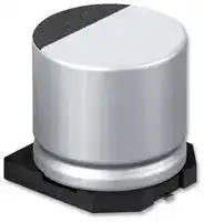
PCH1J560MCL1GS
Polymer Aluminium Electrolytic Capacitor, 56 µF, 63 V, Radial Can - SMD, 0.027 ohm
⚠️ Reference pricing provided. In case of supply shortages, we will connect you with our trusted procurement partners to ensure your project's continuity.
- Manufacturer: NICHICON
- Product type: Aluminium Polymer Capacitors
- ESR: 0.027ohm
- SVHC: No SVHC (16-Jul-2019)
- Capacitance: 56µF
- Voltage(DC): 63V
- Product Range: PCH Series
- Product Width: -
- Product Height: 12mm
- Product Length: -
- Ripple Current: 2.1A
- Product Diameter: 8mm
- Capacitor Mounting: Surface Mount
- Capacitor Terminals: Solder
- Capacitance Tolerance: ± 20%
- Lifetime @ Temperature: 4000 hours @ 135°C
- Capacitor Case / Package: Radial Can - SMD
- Operating Temperature Max: 135°C
- Operating Temperature Min: -55°C
| Delivery and price | |
|---|---|
| Units per pack | 1600 |
| Price | 0.996 € |
| Current stock | 10+ |
| Lead time | 30 days |
Datasheet

**CONDUCTIVE  POLYMER  ALUMINUM  SOLID  ELECTROLYTIC  CAPACITORS**

## **PCH**

Chip Type, Higher Capacitance High Temperature Range

High reliability, High voltage (to 80V). ° Low ESR, High ripple current.Long life of 4000 hours at 135°C. **PCZ** HighTemperature Current **PCH** Frequency HighTemperature **PCR** & SMD type : Lead free reflow soldering condition a ~~t~~ 260°C peak complete correspondence. Compliant to the RoHS directive (2011/65/EU,(EU)2015/863). ESR after Endurance at -40°C.AEC-Q200 Qualified. Please contact us for details. — | | Specifications Item Performance Characteristics ~~|~~ Category Temperature Range –55 to +135°C Rated Voltage Range 16 to 80V ~~rs es~~ Rated Capacitance Range 12 to 1000µF ~~|~~ Capacitance Tolerance ± 20%   at 120Hz, 20°C ~~sn~~ Tangent of loss angle (tan δ) Less than or equal to the specified value at 120Hz, 20°C ESR[ (] 1) Less than or equal to the specified value at 100kHz, 20°C Leakage Current ( 2) After 2 minutes' application of rated voltage, leakage current is not more than 0.03CV. Temperature Characteristics Z(– 55°C) / Z(+20°C) 1.25       (100kHz) (Max.Impedance Ratio) Capacitance change Within ± 20% of initial capacitance value ( 3) The specifications listed at right shall be met when the tan δ 150% or less of the initial specified value Endurance applied for 4000 hourscapacitors are restored to 20°C after  the rated voltage is at 135°C. ESR ( 1) 200% or less of the initial specified value ~~<n~~ Leakage current ( 2) Less than or equal to the initial specified value ~~SS~~ Shelf Life After storing the capacitors under no load at 135°C for 1000 hours and then performing voltage treatment based on JIS C 5101-4 clause 4.1 at 20°C, they shall meet the specified values for the endurance characteristics listed above. ~~es~~ ESR after Endurance[ (] 1) Less than or equal to the specified value at 100kHz, -40°C Capacitance change Within ± 20% of initial capacitance value ( 3) Damp Heat The specifications listed at right shall be met when the tan δ 150% or less of the initial specified value (Steady State) capacitors are restored to 20°C after the rated voltage is applied for 2000 hours at 85°C, 85% RH. ESR ( 1) 200% or less of the initial specified value ~~ed~~ Leakage current ( 2) Less than or equal to the initial specified value ~~a —~~ After soldering the capacitor under the soldering conditions prescribed here, the capacitor shall meet the specifications listed at right. Pre-heating shall be done at 150 to 200°C and for 60 to 180 sec. Capacitance change Within ± 10% of the initial capacitance value ( 3) Resistance to The duration for over +230°C temperature at capacitor surface shall tan δ 130% or less than the initial specified value Soldering Heat not exceed 60 seconds.In case peak temperature is 260°C or less, reflow soldering shall be ESR ( 1) 130% or less than the initial specified value two times maximum. ~~Sd~~ Leakage current ( 2) Less than or equal to the initial specified value Measurement for solder temperature profile shall be made at the ~~a~~ capacitor top. Marking Navy blue print on the case top ~~a —— a~~ 1  ESR should be measured at both of the terminal ends closest where the terminals ※ I : Leakage Current(µA), C : Rated Capacitance(µF), V : Rated Voltage(V) protrude through the plastic platform.

Type numbering system  (Example : 35V 150µF)

2  Conditioning : If any doubt arises, measure the leakage current after the voltage treatment of applying DC rated voltage continuously to the capacitor for 120 minutes at 105°C. 1 2 3 4 5 6 7 8 9 10 11 12 13 14 ~~°~~ 3  Initial value : The value before test of examination of resistance to soldering. P C H 1 OOo) V 1 5 1 M C =O L 1 G S Taping code ~~7~~ Dimensions Size code Standard Positive Configuration Capacitance Lot No. Plastic platform0.3 max. C±0.2 Capacitance tolerance (±20%)Rated capacitance (150µF) StandardSize CodeL ~~a~~ Rated voltage (35V) Vibration ※Please ask for Resistance Part Number. Series name Type φ6.3×8L(φ6.3×8L),φ8×10L(φ8×10.5L),φ10×10L(φ10×10.5L),φ10×12.7L(φ10×13.2L) : The vibration structure-resistant product is also available upon request, please ask for details. 5 im ices (   ) : Size of the vibration structure-resistant product. Series Voltage (V:35V) 4 φφ8,106.3: L: L±0.3±0.5 ! -(le H | Negative Standard (mm) Vibration Resistance  (mm) I - ~~fr~~ Size ~~|~~ φ6.3 × 6L ~~|~~ φ6.3 × 8L ~~f~~ φ8 × 7L ~~f~~ φ8 × 10L ~~ft~~ φ8 × 12L ~~ft~~ φ10 × 8L ~~fy]~~ φ10 × 10L φ10 × 12.7L Size φ6.3 × 8L φ8 × 10.5L φ10 × 10.5L φ10 × 13.2L [ Vibration Resistance ] ® Positive ~~ee~~ φD 6.3 6.3 8.0 8.0 8.0 10.0 10.0 10.0 φD 6.3 8.0 10.0 10.0 Plastic platform L 5.9 7.9 6.9 9.9 11.9 7.9 9.9 12.6 L 7.5 10.0 10.0 12.7 Capacitance Lot No. ~~| | | {| | | ft ft fy~~ 0.3 max. C±0.2 A 7.3 7.3 9.0 9.0 9.0 11.0 11.0 11.0 A 7.3 9.0 11.0 11.0 — ~~| -+— | | | {| | | | | ff~~ B 6.6 6.6 8.3 8.3 8.3 10.3 10.3 10.3 B 6.6 8.3 10.3 10.3 c ~~l~~ in ~~ee~~ C 6.6 6.6 8.3 8.3 8.3 10.3 10.3 10.3 C 6.6 8.3 10.3 10.3 E 2.1 2.1 3.2 3.2 3.2 4.6 4.6 4.6 E 2.5 3.1 4.6 4.6 ~ ~~| | | {| | | fF | ff~~ H 0.5 to 0.8 0.5 to 0.8 0.8 to 1.1 0.8 to 1.1 0.8 to 1.1 0.8 to 1.1 0.8 to 1.1 0.8 to 1.1 H 0.5 to 0.8 1.1 to 1.5 1.1 to 1.5 1.1 to 1.5 Voltage Frequency coefficient of rated ripple current L±0.5 H Series Voltage (V:35V) Negative V 16 20 25 35 50 63 80 Frequency0/ 120Hz 1kHz 10kHz 100kHz or more Code C D E V H J K Coefficient 0.05 0.30 0.70 1.00 Aid electrode ~~ESS~~ Dimension table in next page. ~~ESSE~~ CAT.8100N ~ [

**CONDUCTIVE  POLYMER  ALUMINUM  SOLID  ELECTROLYTIC  CAPACITORS**

## **PCH**

## Dimensions

**==> picture [512 x 52] intentionally omitted <==**

**----- Start of picture text -----**<br>
Low temp.<br>Rated Voltage Surge  Rated Case Size Leakage Current Initial ESR after Rated Ripple<br>(V) Voltage Capacitance tan δ (µA) ESR (mΩ)   Endurance (mArms) Part Number<br>(code) (V) (µF) φD×L(mm) ( at 20℃ after 2 minutes )(20℃/100kHz)(−40℃/100kHz)(mΩ) (135℃/100kHz)<br>120 6.3×6 0.08 57 36 72 900 PCH1C121MCL1GS<br>**----- End of picture text -----**<br>


|Rated Voltage<br>(V)<br>(code)|Surge<br>Voltage<br>(V)|Rated<br>Capacitance<br>(µF)|Case Size<br>φD×L(mm)|tanδ<br>|Leakage Current<br>(µA)<br>(<br>at 20℃ after<br>2 minutes )|Initial<br>ESR (mΩ)<br>(20℃/100kHz)<br><br>|Low temp.<br>ESR after<br>Endurance<br>(mΩ)<br>(−40℃/100kHz)<br>|Rated Ripple<br>(mArms)<br>(135℃/100kHz)|Part Number|
|---|---|---|---|---|---|---|---|---|---|
|||120|6.3×6|0.08|57|36|72|900|PCH1C121MCL1GS|
|16<br>(1C)|20|220|■6.3×8|0.08|105|23|46|1500|PCH1C221MCL4GS|
|||220|8×7|0.08|105|30|60|1100|PCH1C221MCL1GS|
|||470|▲<br>8×10|0.08|225|17|34|2400|PCH1C471MCL6GS|
|||470|10×8|0.08|225|22|44|1900|PCH1C471MCL1GS|
|||560|8×12|0.08|268|16|32|2700|PCH1C561MCL1GS|
|||680|10×10|0.08|326|19|38|2300|PCH1C681MCL1GS|
|||1000|10×12.7|0.08|480|13|26|2500|PCH1C102MCL1GS|
|20<br>(1D)|25|100|6.3×6|0.08|60|41|82|900|PCH1D101MCL1GS|
|||150|■6.3×8|0.08|90|25|50|1200|PCH1D151MCL4GS|
|||150|8×7|0.08|90|39|78|800|PCH1D151MCL1GS|
|||330|▲<br>8×10|0.08|198|19|38|2300|PCH1D331MCL6GS|
|||330|10×8|0.08|198|23|46|1800|PCH1D331MCL1GS|
|||470|8×12|0.08|282|18|36|2500|PCH1D471MCL1GS|
|||560|10×10|0.08|336|20|40|2200|PCH1D561MCL1GS|
|||680|10×12.7|0.08|408|14|28|3000|PCH1D681MCL1GS|
|25<br>(1E)|31|56|6.3×6|0.08|42|43|86|900|PCH1E560MCL1GS|
|||100|■6.3×8|0.08|75|27|54|1100|PCH1E101MCL4GS|
|||100|8×7|0.08|75|41|82|800|PCH1E101MCL1GS|
|||220|▲<br>8×10|0.08|165|20|40|2300|PCH1E221MCL6GS|
|||220|10×8|0.08|165|24|48|1800|PCH1E221MCL1GS|
|||270|8×12|0.08|202|19|38|2300|PCH1E271MCL1GS|
|||330|10×10|0.08|247|20|40|2200|PCH1E331MCL1GS|
|||470|10×12.7|0.08|352|15|30|2900|PCH1E471MCL1GS|
|35<br>(1V)|43|47|6.3×6|0.08|49|48|96|800|PCH1V470MCL1GS|
|||68|■6.3×8|0.08|71|31|62|1100|PCH1V680MCL4GS|
|||68|8×7|0.08|71|44|88|800|PCH1V680MCL1GS|
|||150|▲<br>8×10|0.08|157|22|44|2200|PCH1V151MCL6GS|
|||150|10×8|0.08|157|25|50|1800|PCH1V151MCL1GS|
|||220|8×12|0.08|231|21|42|2300|PCH1V221MCL1GS|
|||270|10×10|0.08|283|20|40|2200|PCH1V271MCL1GS|
|||330|10×12.7|0.08|346|16|32|2800|PCH1V331MCL1GS|
|50<br>(1H)|63|22|6.3×6|0.08|33|50|100|700|PCH1H220MCL1GS|
|||39|■6.3×8|0.08|58|36|72|900|PCH1H390MCL4GS|
|||39|8×7|0.08|58|45|90|900|PCH1H390MCL1GS|
|||82|▲<br>8×10|0.08|123|26|52|2100|PCH1H820MCL6GS|
|||82|10×8|0.08|123|34|68|1600|PCH1H820MCL1GS|
|||120|△<br>8×12|0.08|180|25|50|2100|PCH1H121MCL2GS|
|||120|10×10|0.08|180|25|50|2100|PCH1H121MCL1GS|
|||180|10×12.7|0.08|270|19|38|2500|PCH1H181MCL1GS|
|63<br>(1J)|79|12|6.3×6|0.08|22|51|102|700|PCH1J120MCL1GS|
|||22|■6.3×8|0.08|41|45|90|800|PCH1J220MCL4GS|
|||22|8×7|0.08|41|48|96|800|PCH1J220MCL1GS|
|||39|8×10|0.08|73|28|56|1900|PCH1J390MCL1GS|
|||47|10×8|0.08|88|35|70|1500|PCH1J470MCL1GS|
|||56|8×12|0.08|105|27|54|2100|PCH1J560MCL1GS|
|||68|10×10|0.08|128|28|56|2000|PCH1J680MCL1GS|
|||100|10×12.7|0.08|189|24|48|2100|PCH1J101MCL1GS|
|80<br>(1K)|100|12|6.3×8|0.08|28|50|100|800|PCH1K120MCL1GS|
|||27|8×10|0.08|64|38|76|1000|PCH1K270MCL1GS|
|||39|8×12|0.08|93|35|70|1100|PCH1K390MCL1GS|
|||47|10×10|0.08|112|33|66|1200|PCH1K470MCL1GS|
|||68|10×12.7|0.08|163|28|56|1500|PCH1K680MCL1GS|


For taping specifications, recommended land size/soldering by reflow and minimum order quantity, please refer to the Guidelines for Aluminum Electrolytic Capacitors.

No marked, 1 will be put at 12th digit of type numbering system. : In this case, 2 will be put at 12th digit of type numbering system. : In this case, 4 will be put at 12th digit of type numbering system. : In this case, 6 will be put at 12th digit of type numbering system.

CAT.8100N
Updated at June 10, 2026
About Novapart
Novapart is a B2B electronic component broker specialising in stock shortages and cost reduction. We source hard-to-find parts and identify compliant alternatives across a catalogue of 540,000+ components from 500+ manufacturers.
Learn more →Stock Shortage Specialist
When a component is unavailable, discontinued or has an unacceptable lead time, we tap into our network of vetted European and Asian distributors to source what you need — without compromising on quality or traceability.
Request a quote →Compliant Alternatives
We identify pin-to-pin, electrically equivalent substitutes that meet the same certifications (RoHS, AEC-Q100, REACH) as your original specification — validated against datasheets, not just part numbers. Often at a lower cost.
BOM Analysis service →