
Image not available
Illustrative purposes only

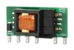
PBO-3C-3
AC/DC PCB Mount Power Supply (PSU), ITE, 1 Output, 1.98 W, 3.3 VDC, 600 mA
⚠️ Reference pricing provided. In case of supply shortages, we will connect you with our trusted procurement partners to ensure your project's continuity.
- Manufacturer: CUI
- Product type: AC / DC PCB Mount Power Supplies
- SVHC: To Be Advised
- Depth: 0
- Width: 11mm
- Height: 0
- Product Range: 0
- No. of Outputs: 1 Output
- Output Power Max: 1.98W
- Input Voltage VAC: 85V AC to 305V AC
- Power Supply Output Type: Fixed
- Output Current - Output 1: 600mA
- Output Current - Output 2: -
- Output Current - Output 3: -
- Output Voltage - Output 1: 3.3VDC
- Output Voltage - Output 2: -
- Output Voltage - Output 3: -
- Power Supply Applications: ITE
| Delivery and price | |
|---|---|
| Units per pack | 50 |
| Price | 2.61 € |
| Current stock | 10+ |
| Lead time | 30 days |
Datasheet

Additional Resources:    Product Page ~~Be~~ |    3D Model |    PCB Footprint

**date** 11/13/2020 **page** 1 of 8

## **SERIES:** PBO-3C **DESCRIPTION:** INTERNAL AC-DC POWER SUPPLY **│**

## **FEATURES**

- wide input range (85 ~ 305 Vac)

- wide operating temperature range (-40 to +85 C)

- IEC/EN/UL 62368 certified

- designed to meet 61558 & 60335 safety standards

- 1,000,000 hour MTBF

- flexible implementations to power a wide array of applications

|an<br>®<br>HousCALsC €|C €|||||||
|---|---|---|---|---|---|---|---|
|**MODEL**|**output**<br>**voltage**||**output**<br>**current**||**output**<br>**power**|**ripple**<br>**and noise¹**|**efficiency²**|
|||**min**||**max**|**max**|**typ**|**typ**|
||(Vdc)|(A)||(A)|(W)|(mVp-p)|**(%)**|
|PBO-3C-3|3.3|0.06||0.6|1.98|150|67.0|
|PBO-3C-5|5.0|0.06||0.6|3.0|150|72.0|
|PBO-3C-9|9.0|0.033||0.333|3.0|150|76.0|
|PBO-3C-12|12.0|0.025||0.25|3.0|150|77.0|
|PBO-3C-15|15.0|0.02||0.2|3.0|150|78.0|
|PBO-3C-24|24.0|0.013||0.125|3.0|150|80.0|


Note:      1. At full load, nominal input, 20 MHz bandwidth oscilloscope, see Application Circuit 10% -100% load. 2. At 230 Vac input.

## **PART NUMBER KEY**

## **- - PBO 3C XX**

Base Number

Output Voltage

**cui** .com

Additional Resources:    Product Page    |    3D Model |    PCB Footprint

**CUI Inc │ SERIES:** PBO-3C **│ DESCRIPTION:** AC-DC POWER SUPPLY

**date** 11/13/2020 **│ page** 2 of 8

|**INPUT**||||||
|---|---|---|---|---|---|
|**parameter**|**conditions/description**|**min**|**typ**|**max**|**units**|
|voltage|ac input<br>dc input|85<br>70||305<br>430|Vac<br>Vdc|
|frequency||47||63|Hz|
|current|at 115 Vac<br>at 230 Vac|||0.12<br>0.06|A<br>A|
|inrush current|at 115 Vac<br>at 230 Vac||13<br>23||A<br>A|
|no load power consumption|at 230 Vac|||0.15|W|
|**OUTPUT**||||||
|**parameter**|**conditions/description**|**min**|**typ**|**max**|**units**|
||3.3 Vdc output models|||820|μF|
||5 Vdc output models|||680|μF|
|capacitive load|9 Vdc output models<br>12 Vdc output models|||470<br>470|μF<br>μF|
||15 Vdc output models|||330|μF|
||24 Vdc output models|||200|μF|
|initial set point accuracy|10% ~ 100% load||±5||%|
|line regulation|at rated load||±1.5||%|
|load regulation|10% ~ 100% load||±3||%|
|temperature coefcient|||±0.15||%/°C|
|**PROTECTIONS**||||||
|**parameter**|**conditions/description**|**min**|**typ**|**max**|**units**|
|over current protection|auto recovery|110|||%|
|short circuit protection|continuous, auto recovery, hiccup|||||
|**SAFETY & COMPLIANCE**||||||
|**parameter**|**conditions/description**|**min**|**typ**|**max**|**units**|
|isolation voltage|input to output for 1 minute, leakage current <5mA|3,000|||Vac|
||certifed toiiiiiii iiiiiiiiii62368: IEC, EN, UL/cUL|||||
|safety approvals|designed to meet<br>61558: IEC, EN|||||
||designed to meet<br>60335: IEC, EN|||||
|safety class|class II|||||
|EMI/EMC|CISPR32/EN55032 CLASS A (Recommended circuit 1, 4)<br>CISPR32/EN55032 CLASS B (Recommended circuit 2, 3)|||||
|ESD|IEC/EN 61000-4-2 Contact ±6KV perf. Criteria B|||||
|radiated immunity|IEC/EN61000-4-3 10V/m perf. Criteria A|||||
|EFT/burst|IEC/EN61000-4-4 ±2KV (Recommended circuit 1, 2) perf. Criteria B<br>IEC/EN61000-4-4 ±4KV (Recommended circuit 3, 4) perf. Criteria B|||||
|surge|IEC/EN61000-4-5 line to line ±1KV (Recommended circuit 1, 2) perf.<br>IEC/EN61000-4-5 line to line±2KV (Recommended circuit 3, 4) perf.||Criteria B<br>Criteria B|||
|conducted immunity|IEC/EN61000-4-6 10Vr.m.s perf. Criteria A|||||
|voltage dips and interruptions|IEC/EN61000-4-11 0%, 70% perf. Criteria B|||||
|MTBF|as per MIL-HDBK-217F at 25 °C<br>1,000,000||||hours|
|RoHS|yes|||||


**cui** .com

Additional Resources:    Product Page    |    3D Model |    PCB Footprint

**CUI Inc │ SERIES:** PBO-3C **│ DESCRIPTION:** AC-DC POWER SUPPLY

**date** 11/13/2020 **│ page** 3 of 8

## **ENVIROMENTAL**

|**ENVIROMENTAL**||||||
|---|---|---|---|---|---|
|**parameter**|**conditions/description**|**min**|**typ**|**max**|**units**|
|operating temperature||-40||85|°C|
|storage temperature||-40||105|°C|
|storage humidity||||95|%|


## **DERATING CURVES**

## **EFFICIENCY CURVES**

**cui** .com

Additional Resources:    Product Page    |    3D Model |    PCB Footprint

**CUI Inc │ SERIES:** PBO-3C **│ DESCRIPTION:** AC-DC POWER SUPPLY

**date** 11/13/2020 **│ page** 4 of 8

## **MECHANICAL**

|**MECHANICAL**||||||
|---|---|---|---|---|---|
|**parameter**|**conditions/description**|**min**|**typ**|**max**|**units**|
|dimensions|26.40 x 12.58 x 11.00 (1.039 x 0.495 x 0.433  inches)||||mm|
|weight|||3.5||g|
|cooling|free air convection|||||


## **MECHANICAL DRAWING**

units: mm [inch]

general tolerance: ±1.00 [±0.039]

|PIN CONNECTIONS|PIN CONNECTIONS|
|---|---|
|PIN|Function|
|1|AC (L)|
|2|AC (N)|
|3|+V (cap)|
|4|-V (cap)|
|5|-Vo|
|6|+Vo|


**==> picture [48 x 7] intentionally omitted <==**

**----- Start of picture text -----**<br>
Non-plated slot<br>**----- End of picture text -----**<br>


Note: There are two, non-metalic/non-plated, slots located between pins 4 and 5 that are required to maintain proper creepage distance and isolation between primary and secondary circuits.

**cui** .com

Additional Resources:    Product Page    |    3D Model |    PCB Footprint

**CUI Inc │ SERIES:** PBO-3C **│ DESCRIPTION:** AC-DC POWER SUPPLY

**date** 11/13/2020 **│ page** 5 of 8

## **APPLICATION DESIGN REFERENCE**

PBO-3C Series additional component selection guide (no EMC devices)

|PBO-3C Series additional component selection guide (no EMC devices)ponent selection guide (no EMC devices)onent selection guide (no EMC devices)guide (no EMC devices)uide (no EMC devices)(no EMC devices)no EMC devices))|PBO-3C Series additional component selection guide (no EMC devices)ponent selection guide (no EMC devices)onent selection guide (no EMC devices)guide (no EMC devices)uide (no EMC devices)(no EMC devices)no EMC devices))|PBO-3C Series additional component selection guide (no EMC devices)ponent selection guide (no EMC devices)onent selection guide (no EMC devices)guide (no EMC devices)uide (no EMC devices)(no EMC devices)no EMC devices))|PBO-3C Series additional component selection guide (no EMC devices)ponent selection guide (no EMC devices)onent selection guide (no EMC devices)guide (no EMC devices)uide (no EMC devices)(no EMC devices)no EMC devices))|PBO-3C Series additional component selection guide (no EMC devices)ponent selection guide (no EMC devices)onent selection guide (no EMC devices)guide (no EMC devices)uide (no EMC devices)(no EMC devices)no EMC devices))|PBO-3C Series additional component selection guide (no EMC devices)ponent selection guide (no EMC devices)onent selection guide (no EMC devices)guide (no EMC devices)uide (no EMC devices)(no EMC devices)no EMC devices))|PBO-3C Series additional component selection guide (no EMC devices)ponent selection guide (no EMC devices)onent selection guide (no EMC devices)guide (no EMC devices)uide (no EMC devices)(no EMC devices)no EMC devices))|PBO-3C Series additional component selection guide (no EMC devices)ponent selection guide (no EMC devices)onent selection guide (no EMC devices)guide (no EMC devices)uide (no EMC devices)(no EMC devices)no EMC devices))|
|---|---|---|---|---|---|---|---|
|Part no.|C11<br>(required)|C2<br>(required)|L1<br>(required)|C32<br>(required)|C4|CY1<br>(required)|TVS3|
|PBO-3C-3|22μF/450V<br>(-40°C to 85°C with<br>85-305 Vac input)<br>10μF/450V<br>(-25°C to 85°C with<br>85-305 Vac input,<br>or<br>-40°C to 85°C with<br>165-305 Vac input)|470μF/6.3V<br>(solid-state capacitor)|4.7μH<br>max 60mΩ/<br>2.2A|150μF/<br>35V|0.1uF/<br>50V<br>(ceramic<br>capacitor)|1.0nF/<br>400Vac|SMBJ7.0A|
|PBO-3C-5||270uF/16V<br>(solid-state capacitor)|||||SMBJ7.0A|
|PBO-3C-9||||47μF/<br>35V|||SMBJ12A|
|PBO-3C-12|||||||SMBJ20A|
|PBO-3C-15||220uF/35V|||||SMBJ20A|
|PBO-3C-24|||||||SMBJ30A|


Note:    1. Recommended to use a capacitor with ripple current >200 mA at 100 kHz.

2. Recommended to use a high frequency, low ESR, electrolytic capacitor (<= 1.1Ω at -40 C) with at least 20% margin on voltage rating.

3. A suppressor diode (TVS) is recommended to protect the downstream application in case of converter failure and should be rated for a minimum of 1.2 times the con verter’s output voltage.

## PBO-3C Series Enviromental and EMC selection guide

|PBO-3C Series Enviromental and EMC selection guideguideuide|PBO-3C Series Enviromental and EMC selection guideguideuide|PBO-3C Series Enviromental and EMC selection guideguideuide|PBO-3C Series Enviromental and EMC selection guideguideuide|PBO-3C Series Enviromental and EMC selection guideguideuide|PBO-3C Series Enviromental and EMC selection guideguideuide|PBO-3C Series Enviromental and EMC selection guideguideuide|
|---|---|---|---|---|---|---|
|Recommended<br>circuit|Application<br>enviromental|Typical<br>industry|Input voltage<br>range|Enviroment<br>temperature|Emissions|Immunity|
|1|Basic application|None|85~305Vac|-40°C to 85°C|Class A|Class III|
|2|Indoor civil<br>enviroment|Smart home/Home<br>appliances (2Y-caps)||-25°C to 55°C|Class B|Class III|
||Indoor general<br>enviroment|Intelligent building/<br>Intelligent agriculture|||||
|3|Indoor industrial<br>enviroment|Manufacturing workoshop||-25°C to 55°C|Class B|Class IV|
|4|Outdoor general<br>enviroment|ITS/Video monitoring/<br>Charging point/<br>Communication/Security<br>and protection||-40°C to 85°C|Class A|Class IV|


|Immunity design circuits reference|Emissions design circuits reference|
|---|---|
|Class III<br>Class IV|Class A<br>Class B|


**cui** .com

Additional Resources:    Product Page    |    3D Model |    PCB Footprint

**CUI Inc │ SERIES:** PBO-3C **│ DESCRIPTION:** AC-DC POWER SUPPLY

**date** 11/13/2020 **│ page** 6 of 8

## **APPLICATION DESIGN REFERENCE (CONTINUED)**

## **Circuit 1**

## **Table 1**

|Application enviromental<br>Ambient temperature range|Imunity Class|Emissions Class|
|---|---|---|
|Basic application<br>-40°C ~ 85°C|Class III|Class A|
||||
|Component|Recommended value||
|FUSE (required)|1A/300V, slow blow|1A/300V, slow blow|
|R1 (wire-wound resistor, required)|12Ω/3W||
|LDM|1.2mH/4Ω max/0.2A min||


Note:   R1 must be a wire-wound resistor; do not use a chip or carbon film resistor.

## **Circuit 2**

**Table 2**

|Application enviromental<br>Ambient temperature range|Imunity Class|Emissions Class|
|---|---|---|
|Indoor civil / general<br>-25°C ~ 55°C|Class III|Class B|
||||
|Component||Recommended value|
|R1 (wire-wound resistor, required)||12Ω/3W|
|LDM||1.2mH/ 4Ω/0.2A|
|CX||0.1µF/310Vac|
|FUSE (required)||1A/300V, slow-blow|


- Note:     1. For Smart Home and Home Appliance applications two Y-capacitors are required in series (2.2 nF/250 Vac each) to meet 60335 household safety requirements. 2. Many safety standards require a bleeder resistor no greater than 3.8MΩ in parallel with the X-capacitor.

3. R1 must be a wire-wound resistor; do not use a chip or carbon film resistor.

**cui** .com

Additional Resources:    Product Page    |    3D Model |    PCB Footprint

**CUI Inc │ SERIES:** PBO-3C **│ DESCRIPTION:** AC-DC POWER SUPPLY

**date** 11/13/2020 **│ page** 7 of 8

## **APPLICATION DESIGN REFERENCE (CONTINUED)**

## **Circuit 3**

**Table 3**

|Application enviromental|Ambient temperature range|Imunity Class|Emissions Class|
|---|---|---|---|
|Indoor industrial|-25°C ~ 55°C|Class IV|Class B|
|||||
|Component|||Recommended value|
|MOV|||S14K350|
|CX|||0.1µF/310Vac|
|LDM|||1.2mH/ 4Ω/0.2A|
|R1 (wire-wound resistor, required)|||12Ω/2W|
|FUSE (required)|||2A/300V, slow-blow|


Note:    1. Many safety standards require a bleeder resistor no greater than 3.8MΩ in parallel with the X-capacitor. 2. R1 must be a wire-wound resistor; do not use a chip or carbon film resistor.

**==> picture [48 x 9] intentionally omitted <==**

**----- Start of picture text -----**<br>
Circuit 4<br>**----- End of picture text -----**<br>


**Table 4**

|Application enviromental<br>Ambient temperature range|Imunity Class<br>Emissions Class|
|---|---|
|Oudoor general enviroment<br>-40°C ~ 85°C|Class IV<br>Class A|
|||
|Component|Recommended value|
|MOV|S14K350|
|LDM|1.2mH/ 4Ω max/0.2A min|
|R1 (wire-wound resistor, required)|12Ω/2W|
|FUSE (required)|2A/300V, slow-blow|


Note:   R1 must be a wire-wound resistor; do not use a chip or carbon film resistor.

**cui** .com

Additional Resources:    Product Page    |    3D Model |    PCB Footprint

**CUI Inc │ SERIES:** PBO-3C **│ DESCRIPTION:** AC-DC POWER SUPPLY

**date** 11/13/2020 **│ page** 8 of 8

## **REVISION HISTORY**

|**rev.**|**description**|**date**|
|---|---|---|
|1.0|initial release|11/13/2020|


The revision history provided is for informational purposes only and is believed to be accurate.

**==> picture [155 x 34] intentionally omitted <==**

**Headquarters** 20050 SW 112th Ave. Tualatin, OR 97062 **800.275.4899**

Fax 503.612.2383 **cui** .com techsupport@cui.com

CUI offers a two (2) year limited warranty.  Complete warranty information is listed on our website.

CUI reserves the right to make changes to the product at any time without notice.  Information provided by CUI is believed to be accurate and reliable.  However, no responsibility is assumed by CUI for its use, nor for any infringements of patents or other rights of third parties which may result from its use.

CUI products are not authorized or warranted for use as critical components in equipment that requires an extremely high level of reliability.  A critical component is any component of a life support device or system whose failure to perform can be reasonably expected to cause the failure of the life support device or system, or to affect its safety or effectiveness.
Updated at June 3, 2026
About Novapart
Novapart is a B2B electronic component broker specialising in stock shortages and cost reduction. We source hard-to-find parts and identify compliant alternatives across a catalogue of 410,000+ components from 500+ manufacturers.
Learn more →Stock Shortage Specialist
When a component is unavailable, discontinued or has an unacceptable lead time, we tap into our network of vetted European and Asian distributors to source what you need — without compromising on quality or traceability.
Request a quote →Compliant Alternatives
We identify pin-to-pin, electrically equivalent substitutes that meet the same certifications (RoHS, AEC-Q100, REACH) as your original specification — validated against datasheets, not just part numbers. Often at a lower cost.
BOM Analysis service →