


PBL500PS48B
AC/DC Open Frame Power Supply (PSU), Medical, 1 Output, 500W @ 30CFM, 250 W, 80V AC to 264V AC
- Manufacturer: XP POWER
- Product type: AC / DC Open Frame Power Supplies
- SVHC: No SVHC (15-Jan-2018)
- Product Range: PBL500 Series
- No. of Outputs: 1 Output
- Input Voltage VAC: 80V AC to 264V AC
- Power Supply Output Type: Fixed
- Output Current - Output 1: 5.21A
- Output Current - Output 2: -
- Output Current - Output 3: -
- Output Current - Output 4: -
- Output Voltage - Output 1: 48VDC
- Output Voltage - Output 2: -
- Output Voltage - Output 3: -
- Output Voltage - Output 4: -
- Power Supply Applications: Medical
- Power Rating (Forced Cooling): 500W @ 30CFM
- Power Rating (Convection Cooling): 250W
| Delivery and price | |
|---|---|
| Units per pack | 5 |
| Price | 201.75 € |
| Current stock | 10+ |
| Lead time | 30 days |
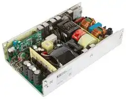
PBL500 series

## 500W **Fan cooled** 250W **Conveccooled** ~~**ton**~~

## **AC-DC power supplies**

The Class II PBL500 series of AC-DC switching power sup in a package of ju ~~s~~ t 180.3 x 101.6 x 39.6mm deliver 450-500W of continuous power with forced air c ~~o~~ oling or 250W with convection cooling. The units are constructed on a U channel for mechanical support and heat sinking. A covered version with integral fan is available to order.

They are designed for medical applications including those needing BF rated insulation with an operation altitude up to 5000 meters.

## **Features**

- f 450-500W fan cooled

- f 250W convection cooled

- f Class II applications

**==> picture [118 x 73] intentionally omitted <==**

**----- Start of picture text -----**<br>
App ns<br>S “A<br>><br>re Home<br>Diagnostics Healthcare<br>**----- End of picture text -----**<br>


## **Dimensions**

**PBL500 (U channel):** 180.3 x 101.6 x 39.6mm (7.1" x 4.0" x 1.56”) **PBL500 (Covered):** 180.3 x 101.6 x 67.0mm (7.1" x 4.0" x 2.64”)

- f Medical (BF) safety approvals

- f U channel 180.3 x 101.6 mm footprint, 39.6mm profile

## **More resources**

- f 5VDC/2A standby, 12VDC/0.3A fan supply

- f Power OK, inhibit & remote sense

**==> picture [93 x 7] intentionally omitted <==**

**----- Start of picture text -----**<br>
Click the link or scan the code<br>**----- End of picture text -----**<br>


- f Class B conducted & radiated emissions

- f 3 year warranty

**==> picture [62 x 8] intentionally omitted <==**

**----- Start of picture text -----**<br>
xppower.com<br>**----- End of picture text -----**<br>


## **Models & ratings**

|Model Number|Output Voltage<br>V1|Output c~~ur~~re~~nt~~|Output c~~ur~~re~~nt~~|Output c~~ur~~re~~nt~~|Standby Supply|Fan Supply<br>V3|Output Power|Output Power|Ripple & Noise|
|---|---|---|---|---|---|---|---|---|---|
|||Convection<br>Fan cooled|Fan cooled||||Convection|Fan cooled||
|PBL500PS12B<br>~~po~~|12V|20.83A|37.50A||5.0V/2.0A|12.0V/0.3A|250W|450W|120mV|
|PBL500PS15B<br>~~po~~|15V|16.67A|30.00A||||||150mV|
|PBL500PS18B<br>~~po~~|18V|13.89A|27.78A|||||500W|180mV|
|PBL500PS24B<br>~~po~~|24V|10.42A|20.84A||||||240mV|
|PBL500PS28B<br>~~po~~|28V|8.93A|17.86A||||||280mV|
|PBL500PS36B<br>~~Po~~|36V|8.94A|13.89A||||||360mV|
|PBL500PS48B|48V|5.21A|10.42A||||||480mV|
|PBL500PS57B|57V|4.38A|8.78A||||||570mV|


Notes:

1. For covered version with integral fan, replace B in the part number with C, e.g PBL500PS12C. V3 not available on covered version.

2. 250W convection cooled or 450-500W with 51m³/h (30cfm) forced air cooling  provided by the user. 450-500W for 'C version'.

3.  Ripple and noise is the maximum peak-to-peak voltage value measured at the output with 20MHz bandwidth, at rated line voltage and output load, and with a 10μF tantalum capacitor in parallel with a 0.1μF ceramic capacitor.

1 [|

**AC-DC power supplies**

## PBL500 series

**==> picture [32 x 31] intentionally omitted <==**

## **Input**

**==> picture [554 x 20] intentionally omitted <==**

**----- Start of picture text -----**<br>
Characteristic Minimum Typical Maximum Units Notes & conditions<br>**----- End of picture text -----**<br>


|Characteristc|Minimum|Typical|Maximum|Units|Notes & conditons|
|---|---|---|---|---|---|
|||||||
|Input voltage|80||264|VAC|Derate to 90% at 85VAC & 80% at 80VAC|
|Input frequency|47||63|Hz||
|Input current - full load||5.2/2.6||A (rms)|115/230VAC, 60/50Hz|
|No load input power|||1|W|When inhibit used|
|Inrush current||30/60||A|115VAC/230VAC at 25°C, cold start|
|Input protection|Internal fuse ftted in line and neutral|||||


## **Output**

**==> picture [553 x 20] intentionally omitted <==**

**----- Start of picture text -----**<br>
Characteristic Minimum Typical Maximum Units Notes & conditions<br>**----- End of picture text -----**<br>


|Characteristic|Minimum|Typical|Maximum|Units|Notes & conditions|
|---|---|---|---|---|---|
|||||||
|Output voltage (V1)|12||57|VDC|See models and ratings table|
|Tolerance|||±2|%|Line and load regulation, 0.1% minimum load required to meet<br>specifcation|
|Transient response|||4|%|Recovery within 1% in less than 500µs for a 25% step load change|
|Ripple & noise|||1|% pk-pk|20MHz bandwidth, see model table notes|
|Overvoltage protection|112||140|ms|Latching|
|Overcurrent protection|105||140|ms|Trip & restart characteristic|
|Thermal shutdown|Protected for overtemperature conditions, latching|||||
|Temperature coefcient|||±0.04|%/°C||
|Standby supply (V2)||5||V|At 2.0A|
|Fan supply (V3)||12||V|At 300mA|
|Patient leakage current||50|80|µA|264VAC, 63Hz|


## **Derating curve**

**==> picture [266 x 135] intentionally omitted <==**

**----- Start of picture text -----**<br>
500<br>450<br>400<br>350<br>300<br>250 PBL500PSxxC<br>PBL500PS12C, PBL500PS15C<br>200<br>150<br>PBL500PSxxB<br>100<br>50<br>0<br>-10 0 10 20 30 40 50 60 70<br>Ambient Temperature (ºC)<br>Output Power (W)<br>**----- End of picture text -----**<br>


Specifications subject to change without notice.

2

**AC-DC power supplies**

## PBL500 series

**==> picture [31 x 31] intentionally omitted <==**

## **Environmental**

**==> picture [553 x 20] intentionally omitted <==**

**----- Start of picture text -----**<br>
Characteristic Minimum Typical Maximum Units Notes & conditions<br>**----- End of picture text -----**<br>


|Characteristic|Minimum|Typical|Maximum|Units|Notes & conditions|
|---|---|---|---|---|---|
|||||||
|Operating temperature|0||+70|°C|Derate linearly from 100% load at 40°C to 50% load at 60°C, safety<br>approved to 40°C|
|Storage temperature|-10||+85|||
|Humidity|5||95|%RH|Non-condensing|
|Cooling (C version)|Integral temperature controlled fan. Fan speed based on temperature of transformer T1, internally monitored. Fan will not rotate until T1<br>temperature reaches approx. 30°C and reaches full speed when T1 temperature reaches approx. 60°C.|||||
|Operating altitude|||5000|m||


## **General**

**==> picture [553 x 30] intentionally omitted <==**

**----- Start of picture text -----**<br>
Characteristic Minimum Typical Maximum Units Notes & conditions<br>Efficiency 90 % 230VAC, 100% load<br>**----- End of picture text -----**<br>


|**Characteristic**|**Minimum**|**Typical**|**Maximum**|**Units**|**Notes & conditions**|
|---|---|---|---|---|---|
|Efciency||90||%|230VAC, 100% load|
|Isolation:     input to output<br>input to ground<br>output to ground|4000|||VAC|2 x MOPP|
||4000|||VAC|2 x MOPP|
||1500|||VAC|1 x MOPP|
|PFC<br>main converter<br>standby converter<br>Switching<br>frequency:|55|65|75|kHz|Fixed|
||90||300||Variable|
||80||120||Variable|
|Hold Up time|20|||ms|At 110VAC & 500W|
|Power density|||0.684 (11.2)|W/cm³(W/in³)||
|Mean time between failure||100,000||Hrs|MIL-HDBK-217F, Full load at 25°C GB|
|Weight||1.01 (2.23)||Kg (lb)|PBL500PSxxB|
|||1.14 (2.52)|||PBL500PSxxC|


## **Signals & controls**

**==> picture [553 x 20] intentionally omitted <==**

**----- Start of picture text -----**<br>
Characteristic Notes & conditions<br>**----- End of picture text -----**<br>


|**Characteristic**|**Notes & conditions**|
|---|---|
|||
|Remote Sense|Compensates for 0.5V total voltage drop.|
|Inhibit|To inhibit, apply TTL high signal.|
|Power OK (POK)|TTL high for normal operation, monitors input bus and output voltage. Turn on delay 100-1000ms, 1ms warning of loss of output<br>following loss of input power.|


Specifications subject to change without notice.

3

**AC-DC power supplies**

## PBL500 series

**==> picture [31 x 31] intentionally omitted <==**

## **Emissions - EMC**

**==> picture [553 x 20] intentionally omitted <==**

**----- Start of picture text -----**<br>
Phenomenon Standard Test level Notes & conditions<br>**----- End of picture text -----**<br>


|Phenomenon|Standard|Test level|Notes & conditions|
|---|---|---|---|
|||||
|Conducted|EN55032/EN55011|Class B||
|Radiated||||
|Harmonic currents|EN61000-3-2|Class A||
|Voltage ficker|EN61000-3-3|||


## **Emissions - immunity**

**==> picture [554 x 20] intentionally omitted <==**

**----- Start of picture text -----**<br>
Phenomenon Standard Test level Criteria Notes & conditions<br>**----- End of picture text -----**<br>


|Phenomenon|Standard|Test level|Criteria|Notes & conditions|
|---|---|---|---|---|
||||||
|ESD immunity|EN61000-4-2|4|A|±8kV contact, ±15kV air|
|Radiated immunity|EN61000-4-3|10V/m|A||
|EFT/burst|EN61000-4-4|±2kV|A||
|Surge|EN61000-4-5|3|A|+/-2kV L-N|
|Conducted|EN61000-4-6|10 Vrms|A||
|Magnetic feld|EN61000-4-8|30 A/m|A||
|Dips and interruptions|100VAC/50Hz|Dip 30% (70 VAC), 500ms|A||
|||Dip 60% (40 VAC), 100ms|B||
|||Int >95% (0 VAC), 10ms|A||
|||Int 100% (0 VAC), 20ms|A||
|||Int 100% (0 VAC), 5000ms|B||
||240VAC/50Hz|Dip 30% (168 VAC), 500ms|A||
|||Dip 60% (96 VAC), 100ms|A||
|||Int >95% (0 VAC), 10ms|A||
|||Int 100% (0 VAC), 20ms|A||
|||Int 100% (0 VAC), 5000ms|B||


## **Safety approvals**

**==> picture [553 x 20] intentionally omitted <==**

**----- Start of picture text -----**<br>
Safety agency Standard Notes & conditions<br>**----- End of picture text -----**<br>


|Safety agency|Standard|Notes & conditions|
|---|---|---|
||||
|UL|IEC60601-1|Medical|
|EN|ES60601-1, CSA C22.2 No.60601-1|Medical|
|CB|EN60601-1|Medical|
|CE|Meets all applicable directives||
|UKCA|Meets all applicable legislation||


Specifications subject to change without notice.

4

**AC-DC power supplies**

## PBL500 series

**==> picture [32 x 31] intentionally omitted <==**

## **Mechanical details**

## **PBL500PSxxB**

**==> picture [239 x 33] intentionally omitted <==**

**==> picture [354 x 336] intentionally omitted <==**

**----- Start of picture text -----**<br>
B: Moun�ng hole, threaded inserts for M3*0.5 screws (8 places)<br>A: Moun�ng hole, threaded inserts for #6-32 screws (8 places)<br>23.5<br>(0.93)<br>107.0<br>(4.21)<br>60.0<br>(2.36) P4<br>P2<br>P3<br>P3<br>P4<br>  13.0 (0.51)  100.1 (3.94)<br> 15.0 (0.59)  150.0 (5.91)<br>39.5<br>(1.56)<br>20.8<br>(0.82)<br>10.8  166.0 (6.54)  7.0 (0.28)<br>(0.42)<br>180.0 (7.09)<br>**----- End of picture text -----**<br>


|Input connector - P1|Input connector - P1||V1 output connector P2|V1 output connector P2|||Signals & controls connector P3|Signals & controls connector P3|Signals & controls connector P3|||V3 output connector P4|V3 output connector P4|
|---|---|---|---|---|---|---|---|---|---|---|---|---|---|
|Pin 1|L||Pin 1|+V1 main output||Pin 1|Common Return|Pin 5||Inhibit||Pin 1|Common Return|
|Pin 2|N||Pin 2|-V1 (common return)||Pin 2|+V1 Sense|Pin 6|+V2|5VDC standby||Pin 2|+V3 12VDC fan|
|||||||Pin 3|-V1 Sense|Pin 7|+V2|5VDC standby||||
|||||||Pin 4|POK|Pin 8|Common Return|||||


## Notes:

1. Dimensions shown in mm (inches)

2. Tolerance 0.5 (0.02) maximum

3.  Input connector P1 is Dinkle terminal P/N DT-35C-B01W-03, with nickel plated M3 screws.

4. Output connector P2 is M4x0.7 screw connections.

5.  Connector P3 is Molex header 87833-08 or equivalent, mating with Molex housing 51110-0850 or equivalent.

6.  Fan connector P4 is JST header S2B-ZR-3.4 or equivalent, mating with JST housing ZHR-2 or equivalent.

7. Weight: 1.01Kg (2.23lbs) approx.

8. Maximum penetration of fixing screws is 4mm from the outer surface of chassis.

Specifications subject to change without notice.

5

**AC-DC power supplies**

## PBL500 series

**==> picture [32 x 31] intentionally omitted <==**

## **Mechanical details**

## **PBL500PSxxC**

**==> picture [217 x 40] intentionally omitted <==**

**==> picture [342 x 309] intentionally omitted <==**

**----- Start of picture text -----**<br>
B: Moun�ng hole, threaded inserts for M3*0.5 screws (8 places)<br>A: Moun�ng hole, threaded inserts for #6-32 screws (8 places)<br>23.5<br>(0.93)<br>107.0<br>(4.21)<br>60.0<br>(2.36)<br>P2<br>P3<br>P3<br>  13.0 (0.51)  100.0 (3.94)<br> 15.0 (0.59)  150.0 (5.91)<br> 17.0 (0.67)<br>67.0<br>(2.64)<br>39.5<br>47.0<br>(1.56)<br>(1.85)<br>20.8<br>(0.82)<br>10.8  166.0 (6.54)  7.0 (0.28)<br>(0.42)<br>180.0 (7.09)<br>**----- End of picture text -----**<br>


|Input connector - P1|Input connector - P1|V1 output connector P2<br>Pin 1<br>+V1 main output<br>Pin 2<br>-V1 (common return)|Signals & controls connector P3|Signals & controls connector P3|Signals & controls connector P3|Signals & controls connector P3|
|---|---|---|---|---|---|---|
|Pin 1|L||Pin 1|Common Return|Pin 5|Inhibit|
|Pin 2|N||Pin 2|+V1 Sense|Pin 6|+V2 5VDC standby|
||||Pin 3|-V1 Sense|Pin 7|+V2 5VDC standby|
||||Pin 4|AC OK|Pin 8|Common Return|


## Notes:

1. Dimensions shown in mm (inches)

2. Tolerance 0.5 (0.02) maximum

3.  Input connector P1 is Dinkle terminal P/N DT-35C-B01W-03, with nickel plated M3 screws.

   5.  Connector P3 is Molex header 87833-08 or equivalent, mating with Molex housing 51110-0850 or equivalent.

   6. Weight: 1.14Kg. (2.52lbs) approx.

   7. Maximum penetration of fixing screws is 4mm from the outer surface of chassis.

4. Output connector P2 is M4x0.7 screw connections.

27 February 2025

**6**
Updated at June 8, 2026
XP Power is a globally recognized leader in the design and manufacture of critical power solutions for the electronics industry. With a steadfast commitment to total quality and in-house engineering expertise, the company delivers highly reliable components that support complex applications across the industrial, healthcare, and technology sectors. Their extensive manufacturing capabilities provide engineers with a broad and dependable source for innovative power products. Our extensive portfolio of XP Power components is heavily focused on robust power and line protection. The core of this offering features a vast selection of high-performance AC/DC converters, designed to meet the rigorous efficiency and footprint demands of modern electronic systems. Complementing these are numerous reliable DC/DC converters, providing versatile options for precise voltage regulation and seamless system integration. Beyond their primary power conversion ranges, XP Power manufactures specialized components to address specific design challenges. Our selection includes essential passive components, such as power line filters for effective EMC and RFI suppression, ensuring signal integrity and strict regulatory compliance. Additionally, we provide dedicated AC/DC LED power supplies tailored for reliable, long-lasting performance in advanced commercial and industrial lighting applications.
About Novapart
Novapart is a B2B electronic component broker specialising in stock shortages and cost reduction. We source hard-to-find parts and identify compliant alternatives across a catalogue of 410,000+ components from 500+ manufacturers.
Learn more →Stock Shortage Specialist
When a component is unavailable, discontinued or has an unacceptable lead time, we tap into our network of vetted European and Asian distributors to source what you need — without compromising on quality or traceability.
Request a quote →Compliant Alternatives
We identify pin-to-pin, electrically equivalent substitutes that meet the same certifications (RoHS, AEC-Q100, REACH) as your original specification — validated against datasheets, not just part numbers. Often at a lower cost.
BOM Analysis service →