
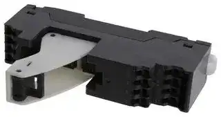


P7SA-10F-ND-PU DC24
RELAY SOCKET, 10 PIN, 6A, 24VDC
- Manufacturer: OMRON INDUSTRIAL AUTOMATION
- Product type: Relay Sockets
- Socket Mounting:DIN Rail; Socket Terminals:Push In; No. of Pins:10Pins; Current Rating:6A; Voltage Rating:24VDC; Product Range:- 51AC8049
- No. of Pins: 10Pins
- Product Range: -
- Current Rating: 6A
- Voltage Rating: 24VDC
- Socket Mounting: DIN Rail
- Socket Terminals: Push In
| Delivery and price | |
|---|---|
| Units per pack | 250 |
| Price | 43.31 € |
| Current stock | 25+ |
| Lead time | 30 days |
## **Relays with Forcibly Guided Contacts G7SA**

## **Compact, Slim Relays Conforming to EN Standards**

- Additional Push-In Plus terminal sockets are used to save wiring work in comparison with traditional screw terminals. (Wiring time is reduced by 60% * in comparison with traditional screw terminals.)

- Relays with forcibly guided contacts (EN 61810-3, Certified by VDE).

- Supports the CE marking of machinery (Machinery Directive).

- Helps detect hazardous machine status when used as part of an interlocking circuit.

- Four-pole and six-pole Relays are available.

- The Relay’s terminal arrangement simplifies PWB pattern design.

**Note:** Sockets are sold separately.

For the most recent information on models that have been certified for safety standards, refer to your OMRON website.

- Reinforced insulation between inputs and outputs. Reinforced insulation between some poles of different polarity.

- According to OMRON actual measurement data

Be sure to read the _Safety Precautions_ on page 13.

## **Model Number Structure**

## **Model Number Legend**

## **Main unit**

**Relays with forcibly guided contacts G7SA-** @ **A** @ **B**

⎯ **1** ⎯ **2**

Specify the power supply voltage (coil rated voltage) when ordering. ~~Le~~ **1. NO Contact Poles 2. NC Contact Poles** 2: DPST-NO 1: SPST-NC 3: 3PST-NO 2: DPST-NC 4: 4PST-NO 3: 3PST-NC

Relays use PCB terminals. This allows for mounting on PCBs and for connection to optional dedicated sockets (order separately). ~~PF~~

5: 5PST-NO

## **Options (order separately)**

## **Sockets**

## **P7SA-** @@ **-** @ **-** @@

⎯⎯⎯⎯⎯⎯⎯⎯⎯ **1 2 3 4 5 6**

## **1. Basic Model Name**

P7SA: Socket for G7SA

## **2. Number of Poles**

10: 4 poles (10 terminals)

14: 6 poles (14 terminals)

## **3. Mounting Type**

F: Front-mounting

P: Back-mounting

**4. LED Indicator**

None: None

ND: With operation indicator/coil surge absorbing diode

## **5. Terminal Type**

Blank: Screw terminals when 3. is F type

PCB terminals when 3. is P type

PU: Push-In Plus terminals

**6. Coil Rated Voltage (V)**

24 VDC: When 4. is ND

**1**

**G7SA**

## **Ordering Information**

## **Main unit**

|**Main unit**|**Main unit**||||||
|---|---|---|---|---|---|---|
|**Relays with Forcibly**||**Guided Contacts**||Specify the coil rated voltage when ordering.|||
|**Terminal type**|**Sealing**|**Poles**|**Contact configuration**||**Coil rated voltage**|**Model**|
|PCB terminals|Flux-tight|4 poles|3PST-NO, SPST-NC||12, 18, 21, 24, 48, 110 VDC|**G7SA-3A1B**|
||||DPST-NO, DPST-NC||12, 18, 21, 24, 48, 110 VDC|**G7SA-2A2B**|
|||6 poles|5PST-NO, SPST-NC||12, 18, 21, 24, 48, 110 VDC|**G7SA-5A1B**|
||||4PST-NO, DPST-NC||12, 18, 21, 24, 48, 110 VDC|**G7SA-4A2B**|
||||3PST-NO, 3PST-NC||12, 18, 21, 24, 48, 110 VDC|**G7SA-3A3B**|


## **Options (order separately) Sockets**

|**Mounting**|**Terminal Type**|**With operation**<br>**indicator/coil**<br>**surge absorbing**<br>**dioder**|**Poles**|**Coil rated**<br>**voltage**|**Appearance**|**Model**|
|---|---|---|---|---|---|---|
|Front-mounting|Push-In Plus terminals|Yes|4 poles|24 VDC||**P7SA-10F-ND-PU DC24**|
||||6 poles|||**P7SA-14F-ND-PU DC24**|
||Screw terminals|Yes|4 poles|||**P7SA-10F-ND DC24**|
||||6 poles|||**P7SA-14F-ND DC24**|
|||No|4 poles|−||**P7SA-10F**|
||||6 poles|||**P7SA-14F**|
|Back-mounting|PCB terminals|No|4 poles|−||**P7SA-10P**|
||||6 poles|||**P7SA-14P**|


**2**

**G7SA**

## **Socket Accessories**

## **Short Bars (For P7SA-** @ **F-ND-PU)**

|**Pitch**|**No. of poles**|**Colors**|**Model***1|
|---|---|---|---|
|5.2 mm|2|Red (RD)<br>Blue (BL)<br>Yellow (YL)|**XW5S-P2.5-2**@|
||3||**XW5S-P2.5-3**@|
||4||**XW5S-P2.5-4**@|
||5||**XW5S-P2.5-5**@*2|


**Note:** Use for crossover wiring of adjacent contact terminals (bottom) within one Socket.

- *1. Replace the box ( @ ) in the model number with the code for the covering color. Color Options: RD = red, BL = blue, YL = yellow Example: XW5S-P2.5-10RD when the covering color is red.

- *2. XW5S-P2.5-5 @ cannot be used with P7SA-10F-ND-PU.

## **Parts for DIN Track Mounting**

|**Type**|**Type**|**Model**|**Minimum Order**<br>**(quantity)**|
|---|---|---|---|
|DIN Tracks|1 m|**PFP-100N**|1|
||0.5 m|**PFP-50N**||
|End Plate*||**PFP-M**|10|
|Spacer||**PFP-S**||


- When mounting DIN track, please use End Plate (Model PFP-M).

**3**

**G7SA**

## **Specifications**

## **Ratings**

## **Safety Relay Unit Coil (4 poles)**

|**Rated voltage**<br>**Item**|**Rated**<br>**current**<br>**(mA)**|**Coil**<br>**resistance**<br>**(**Ω**)**|**Max.**<br>**voltage**<br>**(V)**|**Power**<br>**consumption**<br>**(mW)**|
|---|---|---|---|---|
|**12 VDC**|30|400|110%|Approx. 360|
|**18 VDC**|20|900|||
|**21 VDC**<br>|17.1<br>|1,225<br>|||
|**24 VDC**|15|1,600|||
|**48 VDC**|7.5|6,400|||
|**110 VDC**|3.8|28,810||Approx. 420|


## **Coil (6 poles)**

|**Rated voltage**<br>**Item**|**Rated**<br>**current**<br>**(mA)**|**Coil**<br>**resistance**<br>**(**Ω**)**|**Max.**<br>**voltage**<br>**(V)**|**Power**<br>**consumption**<br>**(mW)**|
|---|---|---|---|---|
|**12 VDC**|41.7|288|110%|Approx. 500|
|**18 VDC**|27.8|648|||
|**21 VDC**|23.8|882|||
|**24 VDC**|20.8|1,152|||
|**48 VDC**|10.4|4,606|||
|**110 VDC**|5.3|20,862||Approx. 580|


## **Contacts**

|**Item**<br>**Load**|**Resistive load**|**Inductive load**<br>**(cosφ=0.3, L/R=48 ms)**|
|---|---|---|
|**Rated load**|250 VAC 6 A<br>30 VDC 6 A|AC15 240 VAC 2 A<br>DC13 24 VDC<br>1 A<br>48 VDC<br>0.5 A<br>110 VDC 0.2 A|
|**Rated carry current**|6 A||
|**Max. switching voltage**|250 VAC, 125 VDC||
|**Max. switching current**|6 A||
|**Contact materials**|Au plating + Ag alloy||


- **Note: 1.** The rated current and coil resistance are measured at a coil temperature of 23°C with tolerances of ±15%.

   **2.** The maximum voltage is based on an ambient operating temperature of 23°C maximum.

## **Characteristics**

## **Safety Relay Unit**

|**Characteristics**<br>**Safety Relay Unit**|**Characteristics**<br>**Safety Relay Unit**||
|---|---|---|
|**Contact resistance*1**||100 mΩmax.|
|**Operating time*2**||20 ms max.|
|**Response time*3**||10 ms max.|
|**Release time*2**||20 ms max.|
|**Must operate voltage**||75% max.|
|**Must release voltage**||10% min.|
|**Maximum operating**<br>**frequency**|**Mechanical**|36,000 operations/h|
||**Rated load**|1,800 operations/h|
|**Insulation resistance*4**||1,000 MΩmin.|
|**Dielectric Strength**<br>***5*6**|**Between coil and**<br>**contacts**|4,000 VAC, 50/60 Hz for 1 min.|
||**Between**<br>**contacts of**<br>**different polarity**|4,000 VAC, 50/60 Hz for 1 min. (except for followings)<br>4 poles (for poles 3-4 in 4-pole Relays),<br>6 poles (for poles 3-5, 4-6, and 5-6 in 6-pole Relays): 2,500 VAC, 50/60 Hz for 1 min.|
||**Between contacts**<br>**of the same polarity**|1,500 VAC, 50/60 Hz for 1 min.|
|**Vibration resistance**||10 to 55 to 10 Hz, 0.75-mm single amplitude (1.5-mm double amplitude)|
|**Shock resistance**|**Destruction**|1,000 m/s2|
||**Malfunction**|100 m/s2|
|**Durability*7**|**Mechanical**|10,000,000 operations min. (at approx. 36,000 operations/h)|
||**Electrical**|100,000 operations min. (at the rated load)|
|**Failure rate (P level)**<br>**(reference value*8)**||5 VDC, 1 mA|
|**Ambient operating temperature*9**||12 to 48 VDC: -40 to 85°C (with no icing or condensation)<br>110 VDC:<br>-40 to 60°C (with no icing or condensation)|
|**Ambient operating humidity**||5% to 85%|
|**Weight**||4 poles: Approx. 22 g<br>6 poles: Approx. 25 g|


- **Note: 1.** The above values are initial values.

   **2.** Performance characteristics are based on coil temperature of 23°C.

- *1. The contact resistance was measured with 1 A at 5 VDC using the voltage-drop method.

- *2. These times were measured at the rated voltage and an ambient temperature of 23°C. Contact bounce time is not included.

- *3. The response time is the time it takes for the normally open contacts to open after the coil voltage is turned OFF. Contact bounce time is included. Measurement conditions: Rated voltage operation, Ambient temperature: 23°C

- *4. The insulation resistance was measured with a 500-VDC megohmmeter at the same locations as the dielectric strength was measured.

- *5. Pole 3 refers to terminals 31-32 or 33-34, pole 4 refers to terminals 43-44, pole 5 refers to terminals 53-54, and pole 6 refers to terminals 63-64.

- *6. When using a P7SA Socket, the dielectric strength between coil contacts/between contacts of different polarity is 2,500 VAC, 50/60 Hz for 1 min.

- *7. The durability is for an ambient temperature of 15 to 35°C and an ambient humidity of 25% to 75%.

- *8. The failure rate is based on an operating frequency of 300 operations/min.

- *9. 12 to 48 VDC: When operating between 70 and 85°C, reduce the rated carry current of 6 A by 0.1 A for each degree above 70°C. (See Fig. 1.) 110 VDC: When operating between 45 and 60°C, reduce the rated carry current of 6 A by 0.27 A for each degree above 45°C. (See Fig. 1.)

**4**

**G7SA**

## **(Fig. 1) Ambient temperature and contact current**

**==> picture [136 x 124] intentionally omitted <==**

**----- Start of picture text -----**<br>
7<br>12 to 48 VDC<br>6<br>5<br>4<br>3<br>2 110 VDC<br>1<br>0<br>45 60 70 85<br>Ambient temperature (°C)<br>Contact current (A)<br>**----- End of picture text -----**<br>


## **Options (order separately)**

## **Sockets**

|||**Push-In Plus terminals**|**Push-In Plus terminals**|**Screw terminals**|**Screw terminals**|**PCB terminals**|**PCB terminals**|
|---|---|---|---|---|---|---|---|
|||**4 poles**|**6 poles**|**4 poles**|**6 poles**|**4 poles**|**6 poles**|
|**Items**<br>**Models**||**P7SA-10F-ND-PU**|**P7SA-14F-ND-PU**|**P7SA-10F(-ND)**|**P7SA-14F(-ND)**|**P7SA-10P**|**P7SA-14P**|
|**Ambient operating temperature**||P7SA-@F-ND(-PU):<br>−20 to +70°C<br>P7SA-@F:<br>−40 to +85°C<br>(with no icing or condensation)||||−40 to +85°C<br>(with no icing or condensation)||
|**Ambient operating humidity**||25% to 85%||||5% to 85%||
|**Continuous carry current**||6 A*1||||||
|**Dielectric**<br>**strength**|**Between coil and**<br>**contact terminals**|4,000 VAC for 1 min.||2,500 VAC for 1 min.||||
||**Between contact**<br>**terminals of different**<br>**polarity**|2,500 VAC for 1 min.||||||
||**Between contact**<br>**terminals of same**<br>**polarity**|1,500 VAC for 1 min.||||||
|**Insulation**|**resistance**|1,000 MΩmin.*2||||||
|**Weight**||Approx. 58 g|Approx. 70 g|Approx. 44 g|Approx. 59 g|Approx. 9 g|Approx. 10 g|


- *1. When operating the P7SA- @ F-ND-PU at a temperature between 50 and 70°C, reduce the continuous current (6 A at 50°C or less) by 0.25 A for each degree above 50°C.

   - When operating the P7SA- @ F-ND at a temperature between 50 and 70°C, reduce the continuous current (6 A at 50°C or less) by 0.3 A for each degree above 50°C.

   - When operating the P7SA- @ F at a temperature between 50 and 85°C, reduce the continuous current (6 A at 50°C or less) by 0.1 A for each degree above 50°C.

- *2. Measurement conditions: For 500 VDC applied to the same location as for dielectric strength measurement.

## **Short Bars (for P7SA-** @ **F-ND-PU)**

|**Application**|**Applicable sockets**|**Models**|**Maximum carry current**|**Ambient operating**<br>**temperature**|**Ambient operating**<br>**humidity**|
|---|---|---|---|---|---|
|Crossover wiring of<br>contact terminals<br>(bottom)|P7SA-@F-ND-PU|**XW5S-P2.5-2**@|24 A|−40 to 55°C|5% to 95%|
|||**XW5S-P2.5-3**@||||
|||**XW5S-P2.5-4**@||||
|||**XW5S-P2.5-5**@||||


## **Certified Standards**

## **Safety Relay Unit**

## **EN Standards, VDE Certified**

|**Models**|**Operating Coil Ratings**|**Standard number**|**Certification No.**|**Contact ratings**|
|---|---|---|---|---|
|G7SA-2A2B<br>G7SA-3A1B<br>G7SA-3A3B<br>G7SA-4A2B<br>G7SA-5A1B|12, 18, 21, 24, 48,<br>110 VDC|EN/IEC 61810-1<br>Electromagnetic relay<br>EN 61810-3<br>Relays with forcibly guided contacts|125547|250 VAC 6 A (Resistive load)<br>30 VDC 6 A (Resistive load)|
|||EN/IEC 60947-5-1||AC15 240 VAC 2 A (Resistive load)<br>DC13 24 VDC<br>1 A (Resistive load)<br>48 VDC<br>0.5 A<br>110 VDC 0.2 A|


**5**

**G7SA**

## **UL Standards Certification (File No. E41515) Industrial Control Devices**

|**Models**|**Category**|**Listed/Recognized**|**Contact ratings**|**Operating Coil ratings**|
|---|---|---|---|---|
|G7SA-2A2B|E41515|Recognized|6 A, 250 VAC (Resistive)<br>6 A, 30 VDC (Resistive)|12, 18, 21, 24, 48,<br>110 VDC|
|G7SA-3A1B|||||
|G7SA-3A3B|||||
|G7SA-4A2B|||||
|G7SA-5A1B|||||


## **CSA standard CSA C22.2 No.14 Industrial Control Devices**

|**Models**|**Class number**|**File No.**|**Contact ratings**|**Operating Coil ratings**|
|---|---|---|---|---|
|G7SA-2A2B|3211-07|LR35535|6 A, 250 VAC (Resistive)<br>6 A, 30 VDC (Resistive)|12, 18, 21, 24, 48,<br>110 VDC|
|G7SA-3A1B|||||
|G7SA-3A3B|||||
|G7SA-4A2B|||||
|G7SA-5A1B|||||


## **South Korea S-mark certified (Rated voltage 24VDC only)**

|**Models**|**Applicable standard number**|
|---|---|
|G7SA-2A2B DC24|KS C IEC 61810-1|
|G7SA-3A1B DC24||
|G7SA-3A3B DC24||
|G7SA-4A2B DC24||
|G7SA-5A1B DC24||


## **CQC**

|**Models**|**Standard number**|**Certification No.**|
|---|---|---|
|G7SA|GB/T, 21711.1|CQC14002119869|


## **Sockets**

## **CE Marking Compliance**

|**Models**|**EMC Directive**|**Low Voltage Directive**|**Machinery Directive**|
|---|---|---|---|
|P7SA (Excluding -P type)|Not applicable|Applicable|Not applicable|
|P7SA-PU|Not applicable|Applicable|Not applicable|


The CE compliance declaration was made in combination with the Safety Relay.

## **EN Standards, VDE Certified**

|**Models**|**Ratings**|**Standard number**|**Certification No.**|
|---|---|---|---|
|P7SA|---|EN61984|40007586|
|**EN Standards, TÜV Certified**||||
|**Models**|**Ratings**|**Standard number**|**Certification No.**|
|P7SA-PU|---|EN61984|R50356981|


## **UL Standards Certification (File No. E87929) Industrial Control Devices**

|**Models**|**Category**|**Listed/Recognized**|
|---|---|---|
|P7SA|SWIV2|Recognized|
|P7SA-PU|SWIV2, SWIV8|Recognized|
|**CSA standard CSA C22.2 No.14 Industrial Control Devices**|||
|**Models**|**Class number**|**File No.**|
|P7SA|3211-07, 3211-87|LR35535|
|P7SA-PU|3211-07, 3211-87|LR35535|


**6**

**G7SA**

**Engineering Data (Reference Value)**

## **Safety Relay Unit**

## **Durability Curve**

## **G7SA-** @ **A** @ **B**

**==> picture [158 x 156] intentionally omitted <==**

**----- Start of picture text -----**<br>
1,000<br>700<br>500 DC1, 30 VDC<br>300<br>AC1, 250 VAC<br>100<br>70<br>50<br>DC13, 24 VDC<br>30<br>AC15, 240 VAC<br>10<br>7<br>5<br>3<br>1<br>0.1 0.3 0.5 0.7 1 3 5 7 10<br>Contact current (A)<br>4 operations) 10<br>�<br>No. of operations (<br>**----- End of picture text -----**<br>


## **Options (order separately) Sockets**

## **Front-connecting Sockets**

**Ambient temperature and contact current P7SA-** @ **F-ND-PU**

|Total*1<br>1 circuit<br>2<br>1<br>0<br>24<br>20<br>16<br>12<br>8<br>4<br>0<br>6<br>7<br>5<br>4<br>3<br>Total*2<br>-10F<br>-14F<br>8<br>5<br>0<br>20<br>17<br>14<br>11<br>5.4<br>3<br>0<br>15<br>12.6<br>10.2<br>7.8<br>Contact current (A)|-20 -10<br>0<br>10<br>20<br>30<br>40<br>50<br>60<br>70<br>80<br>Ambient temperature (°C)|
|---|---|


- *1. When using a G7SA-5A1B relay, be careful not to exceed the total current (24 A). (Example: at 50°C, 5 contacts × 4.8 A)

- *2. Certification conditions for the TÜV certification. Care should be taken not to exceed the total current.

## **P7SA-** @ **F-ND**

## **P7SA-** @ **F**

**==> picture [189 x 124] intentionally omitted <==**

**----- Start of picture text -----**<br>
7<br>P7SA-@F<br>6<br>5<br>4<br>3 P7SA- @ F-ND<br>2<br>1<br>0<br>-40 -30 -20 -10 0 10 20 30 40 50 60 70 80 90<br>Ambient temperature (°C)<br>Contact current (A)<br>**----- End of picture text -----**<br>


**7**

**G7SA**

**Dimensions**

**(Unit: mm)**

## **Safety Relay Unit**

|**Safety Relay Unit**||||||
|---|---|---|---|---|---|
|**4 poles**<br>**G7SA-3A1B**<br>**G7SA-2A2B**||40|max.|0.5|**G7SA-2A2B**<br>Ten, 1.4 dia.<br>(�0.1 tolerance)<br>**Terminal Arrangement/**<br>**Internal Connection Diagram**<br>**(Bottom View)**<br>**G7SA-3A1B**<br>**Printed Circuit Board**<br>**Design Diagram**<br>**(Bottom View)**<br>13 max.<br>0.5<br>1<br>3.5<br>24 max.<br>11.43<br>5.08<br>5.08<br>13.97<br>10.16<br>(1.83)<br>**34**<br>**43**<br>**33**<br>**44**<br>**22**<br>**21**<br>**12**<br>**11**<br>**1**<br>**0**<br>**34**<br>**43**<br>**33**<br>**44**<br>**24**<br>**23**<br>**12**<br>**11**<br>**1**<br>**0**<br>**Note: 1.** Terminals 23-24, 33-34,<br>and 43-44 are normally<br>open. Terminals 11-12 and<br>21-22 are normally closed.<br>**2.** The colors of the cards<br>inside the Relays are as<br>follows: G7SA-3A1B: Blue<br>and G7SA-2A2B: White.|
|||||||
|||||||
|||||||
|**6 poles**<br>**G7SA-5A1B**<br>**G7SA-4A2B**<br>**G7SA-3A3B**||5|0 max.|0|**G7SA-4A2B**<br>**G7SA-3A3B**<br>(�0.1 tolerance)<br>**Terminal Arrangement/**<br>**Internal Connection Diagram**<br>**(Bottom View)**<br>**G7SA-5A1B**<br>**Printed Circuit Board**<br>**Design Diagram**<br>**(Bottom View)**<br>11.43<br>5.08<br>5.08 5.08 5.08<br>13.97<br>10.16<br>(1.83)<br>13 max.<br>1<br>24 max.<br>3.5<br>0.5<br>.5<br>Fourteen, 1.4 dia.<br>**54**<br>**64**<br>**63**<br>**53**<br>**32**<br>**43**<br>**31**<br>**44**<br>**22**<br>**21**<br>**12**<br>**11**<br>**1**<br>**0**<br>**54**<br>**64**<br>**63**<br>**53**<br>**34**<br>**43**<br>**33**<br>**44**<br>**22**<br>**21**<br>**12**<br>**11**<br>**1**<br>**0**<br>**54**<br>**64**<br>**63**<br>**53**<br>**34**<br>**43**<br>**33**<br>**44**<br>**24**<br>**23**<br>**12**<br>**11**<br>**1**<br>**0**<br>**Note: 1.** Terminals 23-24, 33-34,<br>43-44, 53-54, and 63-64<br>are normally open.<br>Terminals 11-12, 21-22,<br>and 31-32 are normally<br>closed.<br>**2.** The colors of the cards<br>inside the Relays are as<br>follows: G7SA-5A1B: Blue,<br>G7SA-4A2B: White, and<br>G7SA-3A3B: Yellow.|
|||||||
|||||||
|||||||


**8**

**G7SA**

## **Options (order separately) Sockets**

## **Front-mounting Sockets Push-In Plus terminals 4 poles P7SA-10F-ND-PU**

**==> picture [512 x 440] intentionally omitted <==**

**----- Start of picture text -----**<br>
Push-In Plus terminals 4 poles Terminals Arrangement/Internal Connections Diagram (Top View)<br>P7SA-10F-ND-PU G7SA-3A1B Mounted G7SA-2A2B Mounted<br>A1 (0) A2 (1) A1 (0) A2 (1)<br>3.4<br>61<br>Operation indicator 35.4<br>100<br>12 34 44 24 12 34 44 22<br>11 33 43 23 11 33 43 21<br>4.5<br>22.5 35.4<br>(4)<br>Note: 1. The numbers in parentheses are traditionally used terminal numbers.<br>2. Terminals 23-24, 33-34, and 43-44 are normally open. Terminals 11-12<br>and 21-22 are normally closed.<br>Push-In Plus terminals 6 poles<br>P7SA-14F-ND-PU Terminals Arrangement/Internal Connections Diagram (Top View)<br>G7SA-5A1B Mounted G7SA-4A2B Mounted G7SA-3A3B Mounted<br>A1 (0) A2 (1) A1 (0) A2 (1) A1 (0) A2 (1)<br>3.4<br>61<br>Operation indicator<br>35.4<br>12 12 12<br>11 11 11<br>100<br>24 34 44 54 64 22 34 44 54 64 22 32 44 54 64<br>23 33 43 53 63 21 33 43 53 63 21 31 43 53 63<br>4.5<br>27.7 35.4<br>**----- End of picture text -----**<br>


**==> picture [168 x 151] intentionally omitted <==**

**----- Start of picture text -----**<br>
3.4<br>61<br>Operation indicator<br>35.4<br>100<br>4.5<br>27.7 35.4<br>(4)<br>**----- End of picture text -----**<br>


**Note: 1.** The numbers in parentheses are traditionally used terminal numbers. **2.** Terminals 23-24, 33-34, 43-44, 53-54, and 63-64 are normally open. Terminals 11-12, 21-22, and 31-32 are normally closed.

## **Accessories for Push-In Plus Sockets**

## **Short Bars (for P7SA-** @ **F-ND-PU)**

## **XW5S-P2.5-** @@

**==> picture [142 x 123] intentionally omitted <==**

**----- Start of picture text -----**<br>
5.2 × (No. of poles −1) +3.7 3<br>23<br>1.6<br>5.2<br>P<br>**----- End of picture text -----**<br>


|**itch**|**Compatible models**|**No. of po**|**les**<br>**P  (mm)**|<br>**Colors**|**Model***|
|---|---|---|---|---|---|
|2 mm|For P7SA-@F-ND-PU|2<br>3<br>4<br>5|5.2|Red (RD)<br>Blue (BL)<br>Yellow (YL)|XW5S-P2.5-2@|
||||10.4||XW5S-P2.5-3@|
||||15.6||XW5S-P2.5-4@|
||||20.8||XW5S-P2.5-5@|


**Note:** Use for crossover wiring of adjacent contact terminals (bottom) within one Socket.

- Replace the box ( @ ) in the model number with the code for the covering color. Color Options: RD = red, BL = blue, YL = yellow

**9**

**G7SA**

## **Front-mounting Sockets Screw terminals 4 poles P7SA-10F, P7SA-10F-ND**

**==> picture [59 x 35] intentionally omitted <==**

The above figure shows with the finger cover mounted.

**Terminal Arrangement/Internal Connection Diagram (Top View) G7SA-3A1B Mounted G7SA-2A2B Mounted**

**==> picture [133 x 127] intentionally omitted <==**

**----- Start of picture text -----**<br>
44 33 34 44 33 34<br>43 43<br>24 22<br>* *<br>23 21<br>12 12<br>11 1 0 11 1 0<br>**----- End of picture text -----**<br>


**==> picture [183 x 136] intentionally omitted <==**

**----- Start of picture text -----**<br>
2R 22.5 max. 60.5 max.<br>Ten,<br>9 max. 5 M3×8<br>72 max.<br>Operation<br>indicator<br>9 max.<br>4 dia.<br>**----- End of picture text -----**<br>


**Note 1:** The front view shows with the finger cover removed.

**2:** Only the -ND Sockets have operation indicators (orange).

*   This display circuit is available only for "-ND" models. **Note:** Terminals 23-24, 33-34, and 43-44 are normally open. Terminals 11-12 and 21-22 are normally closed.

## **Mounting Hole Placement Diagram (Top View)**

**==> picture [89 x 118] intentionally omitted <==**

**----- Start of picture text -----**<br>
Two, 4 dia.  14.5 [±0.2]<br>or M3.5<br>80 [±0.2]<br>**----- End of picture text -----**<br>


**Screw terminals 6 poles P7SA-14F, P7SA-14F-ND**

**==> picture [295 x 141] intentionally omitted <==**

**----- Start of picture text -----**<br>
Terminal Arrangement/Internal Connection Diagram (Top View)<br>G7SA-5A1B  G7SA-4A2B  G7SA-3A3B<br>Mounted Mounted Mounted<br>64 54 64 54 64 54<br>63 53 63 53 63 53<br>44 34 44 34 44 32<br>* * *<br>43 33 43 33 43 31<br>24 12 22 12 22 12<br>23 1 0 11 21 1 0 11 21 1 0 11<br>**----- End of picture text -----**<br>


**==> picture [79 x 46] intentionally omitted <==**

The above figure shows with the finger cover mounted.

*   This display circuit is available only for "-ND" models. **Note:** Terminals 23-24, 33-34, 43-44, 53-54, and 63-64 are normally open. Terminals 11-12, 21-22, and 31-32 are normally closed.

**==> picture [326 x 138] intentionally omitted <==**

**----- Start of picture text -----**<br>
2R 30 max. 60.5 max. Terminals 23-24,<br>Fourteen,<br>9 max. 5 M3 × 8<br>Two, 4 dia. 22 [±0.2]<br>or M3.5<br>72 max.<br>Operation<br>indicator<br>80 [±0.2]<br>9 max.<br>4 dia.<br>Note 1:  The front view shows with the finger cover removed.<br>2:<br>**----- End of picture text -----**<br>


## **Mounting Hole Placement Diagram (Top View)**

**2:** Only the -ND Sockets have operation indicators (orange).

**10**

**G7SA**

## **Parts for DIN Track Mounting**

**==> picture [511 x 419] intentionally omitted <==**

**----- Start of picture text -----**<br>
DIN Track<br>PFP-100N  7.3± [0.15]<br>PFP-50N 4.5<br>35± [0.3] 27± [0.15]<br>1 5 25 10 25 25 10 25 15 (5)* 1<br>1,000 (500)*<br>*The dimensions given in parentheses () are for the PFP-50N.<br>DIN Track<br>PFP-100N2 16<br>4.5<br>35± [0.3] 27 24 29.2<br>1 5 25 25 25 25 1 5 1 1.5<br>10 10<br>1,000<br>End Plate<br>PFP-M 1 0<br>6.2<br>1.8<br>Eight M4<br>pan head<br>screws 1<br>50 35.5 35.3<br>1.8<br>11.5<br>1 0 1.3<br>M4 spring washers 4.8<br>Spacer<br>PFP-S 16<br>5 1 2<br>34.8<br>44.3<br>16.5<br>**----- End of picture text -----**<br>


**11**

**G7SA**

## **Back-mounting Sockets (for PCB) PCB terminals 4 poles P7SA-10P**

**==> picture [512 x 412] intentionally omitted <==**

**----- Start of picture text -----**<br>
0.5 5 0 max. 0.5<br>Terminal Arrangement/Internal  Mounting Hole Placement<br>1 5 max. Connection Diagram  (Bottom View)<br>(Bottom View) (�0.1 tolerance)<br>G7SA-3A1B Mounted<br>0 11 12 33 34<br>Three, 3.2 dia.<br>39.9 [±0.2] (for M3 tapping<br>41.5 max. 1 23 24 43 44 4.1 [±0.2] 24.8 [±0.2] screws)<br>G7SA-2A2B Mounted 10.16<br>0 11 12 33 34<br>13.97 11.43<br>3.5 (7.14) Ten, 1.1 dia.<br>(11.1) 0.4 (11.1) 0.8 5.08 5.08<br>Three, 2.6 dia. 1 21 22 43 44<br>(for M3 tapping screws)<br>Note:  Terminals 23-24, 33-34, and 43-44<br>are normally open. Terminals 11-12<br>4.1 24.8 and 21-22 are normally closed.<br>39.9<br>PCB terminals 6 poles<br>P7SA-14P<br>0.5 60 max. 0.5 Terminal Arrangement/ Mounting Hole Placement<br>Internal Connection  (Bottom View)<br>15 max. Diagram (Bottom View) (�0.1 tolerance)<br>G7SA-5A1B Mounted<br>0 11 12 33 34 53 54<br>Three, 3.2 dia.<br>49.9 [±0.2] (for M3 tapping<br>4.1 [±0.2] 24.8 [±0.2] Fourteen,  screws)<br>41.5 max. 1 23 24 43 44 63 64 1.1 dia.<br>G7SA-4A2B Mounted 10.16<br>0 11 12 33 34 53 54<br>13.97 11.43<br>(7.14)<br>5.08 5.08 5.08 5.08<br>0.4 3.5<br>(11.1) (11.1) 0.8<br>1 21 22 43 44 63 64<br>Three, 2.6 dia. G7SA-3A3B Mounted<br>(for M3 tapping screws) 0 11 12 31 32 53 54 Note:  Terminals 23-24, 33-34, 43-44,<br>53-54, and 63-64 are normally<br>open. Terminals 11-12, 21-22,<br>4.1 24.8 and 31-32 are normally closed.<br>49.9 1 21 22 43 44 63 64<br>**----- End of picture text -----**<br>


**12**

**G7SA**

## **Safety Precautions**

**Be sure to read the** _**Common Precautions for All Relays with Forcibly Guided Contacts**_ **at the following URL: http://www.ia.omron.com/.**

## **Warning Indications**

|**Precautions**<br>**for Safe Use**<br>|Supplementary comments on what to do or<br>avoid doing to use the product safely.<br>Supplementary comments on what to do or|
|---|---|
|**Precautions**<br>**for Correct**<br>**Use**|<br>avoid doing to prevent failure to operate,<br>malfunction, or undesirable effects on product<br>performance|


**==> picture [214 x 84] intentionally omitted <==**

**----- Start of picture text -----**<br>
Release hole<br>Terminal (insertion) hole<br>Short bar insertion holes<br>**----- End of picture text -----**<br>


## **Precautions for Safe Use**

## **Push-In Plus Terminal Sockets (P7SA-** @ **F-ND-PU)**

- Do not wire anything to the release holes.

- Do not tilt or twist a flat-blade screwdriver while it is inserted into a release hole on the terminal block. The terminal block may be damaged.

- Insert a screwdriver into the release holes at an angle. The terminal block may be damaged if the flat-blade screwdriver is inserted straight in.

- Do not allow the flat-blade screwdriver to fall when you are holding it in a release hole.

- Do not bend a wire past its natural bending radius or pull on it with excessive force. Doing so may cause the wire disconnection.

- Do not insert more than one wire into each terminal insertion hole.

- To prevent wiring materials from smoking or igniting, confirm wire ratings and use the wiring materials given in the following table.

|**Recommended wire**|**Stripping length**<br>**(Ferrules not used)**|
|---|---|
|Stranded wire 0.5 to 1.5mm2/AWG20 to 16<br>Solid wire 0.8 to 1.3mm/AWG20 to 16|8 mm|


- Insert a flat-blade screwdriver all the way to the bottom of the release hole. If the flat-blade screwdriver is not inserted correctly, the wire may not be connected correctly.

- When crossover wiring with wires or short bars, make sure not to insert them in the wrong position. It may cause a short circuit, a malfunction, or a failure.

## **Precautions for Correct Use**

## **Wiring**

- The coil terminals have polarity ( + , − ). Inverting the polarity when wiring the terminals will cause the unit not to operate.

- The release time and the response time of the G7SA will be longer when using the P7SA- @ F-ND(-PU), a socket with operation indicator/coil surge absorbing diode, because it has a built-in diode to absorb coil surge. Because of that, confirm operation under actual conditions before using the P7SA- @ F-ND(-PU).

## **Screw Terminal Sockets (P7SA-** @ **F(-ND))**

- Use one of the following wires to connect to the P7SA- @ F(-ND). Stranded wire: 0.75 to 1.5 mm[2] Solid wire: 1.0 to 1.3 mm

- Tighten the screws of the P7SA- @ F(-ND) to a torque of 0.78 to 0.98 N·m.

- Tighten firmly so as not to have any loose wires.

## **Cleaning**

The G7SA is not of enclosed construction. Therefore, do not wash the G7SA with water or detergent.

## **Mounting**

The G7SA can be installed in any direction.

## **Mounting and Removing the Relays to and from the Socket**

**<Using with front-connecting sockets, Push-In Plus terminal sockets (P7SA-** @ **F-ND-PU)>**

- After mounting the relay, make sure to lock the lock hook. If not, the relay may become loose upon vibration or impact.

- When removing the relay, (1) unlock the lock hook on the release side, (2) then press the release lever.

- You can release the locked block easily by inserting a tip of a flat screwdriver into the square hole.

## **Removing the relay**

**With the relay mounted**

**==> picture [61 x 60] intentionally omitted <==**

**==> picture [59 x 58] intentionally omitted <==**

**==> picture [100 x 36] intentionally omitted <==**

**----- Start of picture text -----**<br>
Lock hook (1)<br>Release lever (2)<br>**----- End of picture text -----**<br>


- <Using with P7SA- @ F-ND-PU Push-In Plus terminal sockets>

- If there is lubrication, such as oil, on the tip of the flat-blade screwdriver, the flat-blade screwdriver may fall and possibly injure a worker.

- Do not insert short bar in the hole for wire or screw driver, it may cause the result of failure of pull out. If insert short bar in the hole for wire or screw driver and try to pull out, it may cause damage for short bar or socket.

## **<Using with front-connecting sockets, screw terminal sockets (P7SA-10F(-ND), P7SA-14F (-ND))>**

Refer to _Common Precautions for All Relays with Forcibly Guided Contacts_ at the following URL: http://www.ia.omron.com/.

- 5-1-1. _Front-connecting Sockets_

- 5-1-2. _Direction for Inserting and Removing Relays_

- 5-3. Common Items

**13**

**G7SA**

## **<Using with back-connecting sockets, PCB terminal sockets (P7SA-10P, P7SA-14P)>**

Refer to _Common Precautions for All Relays with Forcibly Guided Contacts_ at the following URL: http://www.ia.omron.com/.

- 5-1-3. _Soldering of Terminals_

- 5-2. PCB Relays

- 5-3. Common Items

## **2. Removing Wires from the Push-In Plus Terminal Block**

Use the following procedure to remove wires from the terminal block. The same method is used to remove stranded wires, solid wires, and ferrules.

**1.** Hold a flat-blade screwdriver at an angle and insert it into the release hole.

**2.** With the flat-blade screwdriver still inserted into the release hole, remove the wire from the terminal insertion hole.

**3.** Remove the flat-blade screwdriver from the release hole.

## **Push-In Plus Terminal Sockets (P7SA-** @ **F-ND-PU)**

## **1. Connecting Wires to the Push-In Plus Terminal Block**

## **Part Names of the Terminal Block**

**==> picture [62 x 16] intentionally omitted <==**

**----- Start of picture text -----**<br>
Release hole<br>Terminal (insertion) hole<br>**----- End of picture text -----**<br>


**==> picture [162 x 65] intentionally omitted <==**

**----- Start of picture text -----**<br>
Flat-blade<br>1 3 screwdriver<br>3 1<br>10 to 15°<br>2 2<br>Wire<br>**----- End of picture text -----**<br>


## **3. Recommended Ferrules and Crimp Tools**

## **Recommended ferrules**

## **Connecting Wires with Ferrules and Solid Wires**

Insert the solid wire or ferrule straight into the terminal block until the end strikes the terminal block.

**==> picture [59 x 55] intentionally omitted <==**

**==> picture [63 x 37] intentionally omitted <==**

**----- Start of picture text -----**<br>
Release hole<br>Terminal (insertion) hole<br>Ferrules or solid wires<br>**----- End of picture text -----**<br>


- If a wire is difficult to connect because it is too thin, use a flat-blade screwdriver in the same way as when connecting stranded wire.

|**Applicable**<br>**wire**<br>**C**<br>**(mm2)**<br>**(AWG)**|**Applicable**<br>**wire**<br>**C**<br>**(mm2)**<br>**(AWG)**|**Ferrule**<br>**onductor**<br>**Length**<br>**(mm)**|**Stripping**<br>**length**<br>**(mm)**<br>**(Ferrules**<br>**used)**|<br>**Recommended ferrules**|<br>**Recommended ferrules**|<br>**Recommended ferrules**|
|---|---|---|---|---|---|---|
|||||<br>**Phoenix Contact**<br>**product**<br>**Weidmuller**<br>**product**<br>**Wago**<br>**product**|||
|0.5|20|8|10|AI 0,5-8|H0.5/14|216-201|
|||10|12|AI 0,5-10|H0.5/16|216-241|
|0.75|18|8|10|AI 0,75-8|H0.75/14|216-202|
|||10<br>|12<br>|AI 0,75-10<br>|H0.75/16<br>|216-242<br>|
|1/1.25|18/17|8<br>10|10<br>12|AI 1-8<br>AI 1-10|H1.0/14<br>H1.0/16|216-203<br>216-243|
|1.25/1.5|17/16|8|10|AI 1,5-8|H1.5/14|216-204|
|||10|12|AI 1,5-10|H1.5/16|216-244|
|Recommended crimp tool||||CRIMPFOX6<br>CRIMPFOX6T-F<br>CRIMPFOX10S|PZ6 roto|Variocrimp4|


- **Note: 1.** Make sure that the outer diameter of the wire coating is smaller than the inner diameter of the insulation sleeve of the recommended ferrule.

   **2.** Make sure that the ferrule processing dimensions conform to the following figures.

## **Connecting Stranded Wires**

Use the following procedure to connect the wires to the terminal block.

**==> picture [29 x 5] intentionally omitted <==**

**----- Start of picture text -----**<br>
8 to 10 mm<br>**----- End of picture text -----**<br>


**1.** Hold a flat-blade screwdriver at an angle and insert it into the release hole.

   - The angle should be between 10° and 15°. If the flat-blade screwdriver is inserted correctly, you will feel the spring in the release hole.

**2.** With the flat-blade screwdriver still inserted into the release hole, insert the wire into the terminal hole until the end strikes the terminal block.

**3.** Remove the flat-blade screwdriver from the release hole.

**==> picture [203 x 58] intentionally omitted <==**

**----- Start of picture text -----**<br>
Flat-blade<br>1 3 screwdriver 3 1<br>10 to15°<br>2<br>2 Stranded wires<br>**----- End of picture text -----**<br>


## **Checking Connections**

- After the insertion, pull gently on the wire to make sure that it will not come off and the wire is securely fastened to the terminal block.

- If you use a ferrule with a conductor length of 10 mm, part of the conductor may be visible after the ferrule is inserted into the terminal block, but the product insulation distance will still be satisfied.

1.9 mm max. 2.6 mm max.

## **Recommended Flat-blade Screwdriver**

Use a flat-blade screwdriver to connect and remove wires. Use the following flat-blade screwdriver.

The following table shows manufacturers and models as of 2015/Dec.

**==> picture [109 x 55] intentionally omitted <==**

**----- Start of picture text -----**<br>
Side Front<br>2.5 mm dia.<br>0.4 mm 2.5 mm<br>**----- End of picture text -----**<br>


|**Model**|**Manufacturer**|
|---|---|
|SZS 0,4×2,5<br>SZF 0-0,4×2,5*|Phoenix Contact|
|ESD 0,40×2,5|Wera|
|0.4×2.5×75 302|Wiha|
|AEF.2,5×75|Facom|
|210-719|Wago|
|SDI 0.4×2.5×75|Weidmuller|


- OMRON's exclusive purchase model XW4Z-00B is available to order as SZF 0-0,4×2,5 (manufactured by Phoenix Contact).

**14**

## **Terms and Conditions Agreement**

## **Read and understand this catalog.**

Please read and understand this catalog before purchasing the products. Please consult your OMRON representative if you have any questions or comments.

## **Warranties.**

(a) Exclusive Warranty. Omron’s exclusive warranty is that the Products will be free from defects in materials and workmanship for a period of twelve months from the date of sale by Omron (or such other period expressed in writing by Omron). Omron disclaims all other warranties, express or implied. (b) Limitations. OMRON MAKES NO WARRANTY OR REPRESENTATION, EXPRESS OR IMPLIED, ABOUT NON-INFRINGEMENT, MERCHANTABILITY OR FITNESS FOR A PARTICULAR PURPOSE OF THE PRODUCTS. BUYER ACKNOWLEDGES THAT IT ALONE HAS DETERMINED THAT THE PRODUCTS WILL SUITABLY MEET THE REQUIREMENTS OF THEIR INTENDED USE.

Omron further disclaims all warranties and responsibility of any type for claims or expenses based on infringement by the Products or otherwise of any intellectual property right. (c) Buyer Remedy. Omron’s sole obligation hereunder shall be, at Omron’s election, to (i) replace (in the form originally shipped with Buyer responsible for labor charges for removal or replacement thereof) the non-complying Product, (ii) repair the non-complying Product, or (iii) repay or credit Buyer an amount equal to the purchase price of the non-complying Product; provided that in no event shall Omron be responsible for warranty, repair, indemnity or any other claims or expenses regarding the Products unless Omron’s analysis confirms that the Products were properly handled, stored, installed and maintained and not subject to contamination, abuse, misuse or inappropriate modification. Return of any Products by Buyer must be approved in writing by Omron before shipment. Omron Companies shall not be liable for the suitability or unsuitability or the results from the use of Products in combination with any electrical or electronic components, circuits, system assemblies or any other materials or substances or environments. Any advice, recommendations or information given orally or in writing, are not to be construed as an amendment or addition to the above warranty.

See http://www.omron.com/global/ or contact your Omron representative for published information.

## **Limitation on Liability; Etc.**

OMRON COMPANIES SHALL NOT BE LIABLE FOR SPECIAL, INDIRECT, INCIDENTAL, OR CONSEQUENTIAL DAMAGES, LOSS OF PROFITS OR PRODUCTION OR COMMERCIAL LOSS IN ANY WAY CONNECTED WITH THE PRODUCTS, WHETHER SUCH CLAIM IS BASED IN CONTRACT, WARRANTY, NEGLIGENCE OR STRICT LIABILITY.

Further, in no event shall liability of Omron Companies exceed the individual price of the Product on which liability is asserted.

## **Suitability of Use.**

Omron Companies shall not be responsible for conformity with any standards, codes or regulations which apply to the combination of the Product in the Buyer’s application or use of the Product. At Buyer’s request, Omron will provide applicable third party certification documents identifying ratings and limitations of use which apply to the Product. This information by itself is not sufficient for a complete determination of the suitability of the Product in combination with the end product, machine, system, or other application or use. Buyer shall be solely responsible for determining appropriateness of the particular Product with respect to Buyer’s application, product or system. Buyer shall take application responsibility in all cases.

NEVER USE THE PRODUCT FOR AN APPLICATION INVOLVING SERIOUS RISK TO LIFE OR PROPERTY OR IN LARGE QUANTITIES WITHOUT ENSURING THAT THE SYSTEM AS A WHOLE HAS BEEN DESIGNED TO ADDRESS THE RISKS, AND THAT THE OMRON PRODUCT(S) IS PROPERLY RATED AND INSTALLED FOR THE INTENDED USE WITHIN THE OVERALL EQUIPMENT OR SYSTEM.

## **Programmable Products.**

Omron Companies shall not be responsible for the user’s programming of a programmable Product, or any consequence thereof.

## **Performance Data.**

Data presented in Omron Company websites, catalogs and other materials is provided as a guide for the user in determining suitability and does not constitute a warranty. It may represent the result of Omron’s test conditions, and the user must correlate it to actual application requirements. Actual performance is subject to the Omron’s Warranty and Limitations of Liability.

## **Change in Specifications.**

Product specifications and accessories may be changed at any time based on improvements and other reasons. It is our practice to change part numbers when published ratings or features are changed, or when significant construction changes are made. However, some specifications of the Product may be changed without any notice. When in doubt, special part numbers may be assigned to fix or establish key specifications for your application. Please consult with your Omron’s representative at any time to confirm actual specifications of purchased Product.

## **Errors and Omissions.**

Information presented by Omron Companies has been checked and is believed to be accurate; however, no responsibility is assumed for clerical, typographical or proofreading errors or omissions.

## **Note: Do not use this document to operate the Unit.**

**OMRON Corporation Industrial Automation Company Kyoto, JAPAN**

**Contact : www.ia.omron.com**

## **Authorized Distributor:**

## _**Regional Headquarters**_

## **OMRON EUROPE B.V.**

Wegalaan 67-69, 2132 JD Hoofddorp The Netherlands Tel:  (31) 2356-81-300    Fax: (31) 2356-81-388

**OMRON ASIA PACIFIC PTE. LTD.**

438B Alexandra Road, #08-01/02 Alexandra Technopark, Singapore 119968 Tel:  (65) 6835-3011    Fax: (65) 6835-3011

## **OMRON ELECTRONICS LLC**

2895 Greenspoint Parkway, Suite 200 Hoffman Estates, IL 60169 U.S.A. Tel:  (1) 847-843-7900    Fax: (1) 847-843-7787

## **OMRON (CHINA) CO., LTD.**

Room 2211, Bank of China Tower, 200 Yin Cheng Zhong Road, PuDong New Area, Shanghai, 200120, China Tel:  (86) 21-6023-0333    Fax: (86) 21-5037-2388

©OMRON Corporation 2000-2026  All Rights Reserved. In the interest of product improvement, specifications are subject to change without notice.

**CSM_12_14**

**Cat. No. J120-E1-13** 0226 (0100)
Updated at June 6, 2026
With a legacy spanning over 80 years, Omron Industrial Automation is a globally recognized leader in the manufacture of advanced industrial control and automation components. Renowned for their reliability and engineering excellence, Omron delivers comprehensive solutions that enhance efficiency, machine safety, and precision across a wide range of manufacturing environments. Our extensive portfolio of Omron products is heavily focused on their industry-leading sensing and switching technologies. We offer a vast selection of sensors, excelling specifically in high-performance proximity sensors, light sensors, and temperature sensors. Complementing this range are robust switching solutions, featuring a deep inventory of power relays, solid-state relays, safety relays, and essential relay accessories designed for demanding operational requirements. Beyond sensing and switching, Omron is highly regarded for its precision automation and process control equipment. Our selection features highly accurate temperature controllers, versatile process controllers, and sophisticated panel displays and instrumentation. To support these fundamental systems, we also supply dependable Omron power supplies, notably AC/DC converters, alongside vital connectivity components like DIN rail terminal blocks to ensure secure, efficient, and complete industrial setups.
About Novapart
Novapart is a B2B electronic component broker specialising in stock shortages and cost reduction. We source hard-to-find parts and identify compliant alternatives across a catalogue of 410,000+ components from 500+ manufacturers.
Learn more →Stock Shortage Specialist
When a component is unavailable, discontinued or has an unacceptable lead time, we tap into our network of vetted European and Asian distributors to source what you need — without compromising on quality or traceability.
Request a quote →Compliant Alternatives
We identify pin-to-pin, electrically equivalent substitutes that meet the same certifications (RoHS, AEC-Q100, REACH) as your original specification — validated against datasheets, not just part numbers. Often at a lower cost.
BOM Analysis service →