
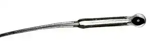


P60DB503M
THERMISTOR, NTC, 50K, WIRE LEADED
- Manufacturer: AMPHENOL ADVANCED SENSORS
- Product type: Temperature Sensing / Compensation NTC Thermistors
- Product Range: P60 Series
- Thermistor Terminals: Wire Leaded
- Operating Temperature Max: 300°C
- Zero Power Resistance at 25°C: 50kohm
| Delivery and price | |
|---|---|
| Units per pack | 250 |
| Price | 12.62 € |
| Current stock | 10+ |
| Lead time | 30 days |
## NTC Miniature Series

Thermometrics Thermoprobes

## Applications

## **NTC Type P20, P25 and P30**

- Miniature bead-in-glass probes feature high reliability, ease of handling and very fast response time. The longer body length makes them particularly well-suited for applications where fast response and immersion in fluids are the major requirements.

## **NTC Type P60, P65, P85 and P100**

- Thermoprobes are recommended for all low cost , general purpose applications involving temperature measurement and control, circuit temperature compensation, liquid level sensing or fluid flow sensing. They are ideally suited for applications, that require a reliable, low cost sensor.

## Descriptions

## **NTC Type P20, P25 and P30**

- The Type P20, P25 and P30 miniature thermprobes consist of a small bead thermistor hermetically sealed in the tip of a shock-resistant solid glass rod. The miniature thermoprobes have improved stability over glass coated and ruggedized glass bead thermistors.

## **NTC Type P60, P65, P85 and P100**

- The Type P60, P65, P85 and P100 thermoprobes consist of a large bead thermistor hermetically sealed in the tip of a shock resistant solid glass rod. They have excellent long-term stability.

## **Amphenol Advanced Sensors**

## Type P20/25/30 Specifications

NTC Types P20/25/30 dimensions

Thermal and Electrical Properties _(All Def initions and Test Methods are Per MIL-PRF-23648)_

|Body<br>Dimensions:|Thermistor Type:|||P20|P25|P30|
|---|---|---|---|---|---|---|
||||Minimum Diameter:|.020 in (.51 mm)|.025 in (.64 mm)|030 in (.76 mm)|
||Standard||code “AA”|.063 in (1.6 mm)|—|—|
||Body|“L”|code “A”|.125 in (3.2 mm)|.125 in (3.2 mm)|.125 in (3.2 mm)|
||Lengths||code “B”|.250 in (6.3 mm)**|.250 in (6.3 mm)|.250 in (6.3 mm)|
|Lead-wires:|||||||
||||Nom. Diameter:|.0011 in (.03 mm)|.002 in (.05 mm)|.003 in (.08 mm)|
||||Minimum Lead Length:|.250 in (6.3 mm)|.250 in (6.3 mm)|.250 in (6.3 mm)|
||||Lead Material:|Platinum Alloy|Platinum Alloy|Platinum Alloy|
|Material System:||||Nominal|Nominal||
|||||Resistance|Resistance|Resistance|
|Code|R-vs-T||25/125|Range @|Range @|Range @|
|Letter|Curve||Ratio|77°F (25°C)|77°F (25°C)|77°F (25°C)|
|E|0||5.0|—|—|—|
|A|1||11.8|300 Ω to 680 Ω|300 Ω to 680 Ω|100 Ω to 300 Ω|
|A|2||12.5|680 Ω to 1.6 kΩ|680 Ω to 1.6 kΩ|300 Ω to 750 Ω|
|A|3||14.0|1.6 kΩ to 3.6 kΩ|1.6 kΩ to 3.6 kΩ|750 Ω to 1.5 kΩ|
|A|4||16.9|3.6 kΩ to 6.8 kΩ|3.6 kΩ to 6.8 kΩ|1.5 kΩ to 3.0 kΩ|
|A|5||19.8|6.8 kΩ to 27 kΩ|6.8 kΩ to 27 kΩ|.0 kΩ to 6.8 kΩ|
|A|6||22.1|–|–|6.8 kΩ to 13 kΩ|
|A|7||22.7|27 kΩ to 75 kΩ|27 kΩ to 75 kΩ|13 kΩ to 18 kΩ|
|B|8||29.4|75 kΩ to 130 kΩ|75 kΩ to 130 kΩ|18 kΩ to 51 kΩ|
|B|9||30.8|130 kΩ to 240 kΩ|130 kΩ to 240 kΩ|51 kΩ to 82 kΩ|
|B|10||32.3|240 kΩ to 360 kΩ|240 kΩ to 360 kΩ|82 kΩ to 150 kΩ|
|B|11||35.7|360 kΩ to 820 kΩ|360 kΩ to 820 kΩ|150 kΩ to 330 kΩ|
|B|12||38.1|820 kΩ to 1.3 MΩ|820 kΩ to 1.3 MΩ|330 kΩ to 680 kΩ|
|B|13||45.0|1.3 MΩ to 3.3 MΩ|1.3 MΩ to 3.3 MΩ|680 kΩ to 1.5 MΩ|
|B|14||48.1|3.3 MΩ to 6.8 MΩ|3.3 MΩ to 6.8 MΩ|1.5 MΩ to 3.0 MΩ|
|B|15||56.5|6.8 MΩ to 10 MΩ|6.8 MΩ to 10 MΩ|3.0 MΩ to 6.2 MΩ|
|D|16||75.6|—|—|6.2 MΩ to 10 MΩ|
|D|16||81.0|—|—|—|
|Thermal Time Constant:|||Still Air at 77°F (25°C):|1.6 sec|2.0 sec|3.0 sec|
||||Plunge into Water:|18 msec|23 msec|60 msec|
|Dissipation Constant:|||Still Air at 77°F (25°C):|.14 mW/°C|.16 mW/°C|.30 mW/°C|
||||Still Water at 77°F (25°C):|.70 mW/°C|.80 mW/°C|1.50 mW/°C|
|Power Rating: (in air)|||Maximum Power Rating:|.020 Watts|.025 Watts|.035 Watts|
||||100% Max. Power to:|302 (150°C)|302 (150°C)|302 (150°C)|
||||Derated to 0% at:|572°F (300°C)|572°F (300°C)|572°F (300°C)|


Resistance vs temperature characterstics: The nominal resistance range for the zero-power resistance at 77°F (25°C) is shown for each miniature bead-in-glass thermoprobe type and each available material system. Each material system is denoted by an ordering code letter, a referenced curve number and the nominal 77°F/257°F (25°C/125°C) resistance ratio.

**2**

## Type 60/65/85/100 Specifications

All thermoprobes are aged for extended periods of time. As such, they exhibit excellent stability for all service temperatures at or below the aging temperature. Thermoprobes that are manufactured with material system “E” are aged at 221°F (105°C); those manufactured with a material system having a 77°F (25°C)/257°F (125°C) ratio of 16.9 or less are aged at 392°F (200°C); and all other material systems are aged at 572°F (300°C). Intermittent operation at temperatures up to 1112°F (600°C) is permissable, however, degraded stability will result when the aging temperature is exceeded. This appiles to the NTC Type P20/25/30 also.

NTC Types 60/65/85/100 dimensions

## Probe Length Codes

|Probe Length Codes|||||||||||
|---|---|---|---|---|---|---|---|---|---|---|
|Probe Length Code Letter|A|B|C|D|F|H|K|M|P|R|
|Tolerance Code Length in (mm)|0.125<br>(3.17)|0.25<br>(6.35)|0.375<br>(9.52)|0.5<br>(12.7)|0.75<br>(19.05)|1<br>(24.4)|1.25<br>(3.75)|1.5<br>(38.1)|1.75<br>(44.45)|2<br>(50.8)|


Thermal and Electrical Properties _(All Def initions and Test Methods are Per MIL-PRF-23648)_

|Body Dimensions|Thermistor Type:||P60|P65|P85|P100|
|---|---|---|---|---|---|---|
|||Maximum Diameter:|.060 in (1.5 mm)|.065 in (1.7 mm)|.085 in (2.2 mm)|.100 in (2.5 mm)|
|||Standard Length Code “B”|.250 in (6.3 mm)|.250 in (6.3 mm)|.250 in (6.3 mm)|.250 in (6.3 mm)|
|||Standard Length Code “D”|.500 in (12.7 mm)|.500 in (12.7 mm)|.500 in (12.7 mm)|.500 in (12.7 mm)|
|||Length Codes Available|“A”, “C”|“A”, “C”|“A”, “C”, “F”, “H”|“A”, “C”, “F”, “H”|
|||(Special Order Only)||||“K”, “M”, “P”, “R”|
|lead-wires:|||||||
|||Nom. Diameter:|.008 in (.20 mm)|.008 in (.20 mm)|.012 in (.30 mm)|.012 in (.30 mm)|
|||Minimum Lead Length:|.875 in (22 mm)|.875 in (22 mm)|.875 in (22 mm)|.875 in (22 mm)|
|||Lead Material:|Tinned Dumet|Tinned Dumet|Tinned Dumet|Tinned Dumet|
|Material System:||Nominal|Nominal|Nominal|Nominal|Nominal|
|||Resistance|Resistance|Resistance|Resistance|Resistance|
|Code<br>Letter|R-vs-T<br>Curve|25/125 Ratio|Range @ 77°F (25°C)|Range @ 77°F (25°C)|Range @ 77°F (25°C)|Range @ 77°F (25°C)|
|E|0|5.0|30 to 51 Ω|30 to 51 Ω|30 to 51 Ω|30 to 51 Ω|
|A|1|11.8|51 to 150 Ω|51 to 150 Ω|51 to 150 Ω|51 to 150 Ω|
|A|2|12.5|150 to 360 Ω|150 to 360 Ω|150 to 360Ω|150 to 360 Ω|
|A|3|14.0|360 to 750 Ω|360 to 750 Ω|360 to 750 Ω|360 to 750 Ω|
|A|4|16.9|750 to 1.5 kΩ|750 to 1.5 kΩ|750 to 1.5 kΩ|750 to 1.5 kΩ|
|A|5|19.8|1.5 k to 3.6 kΩ|1.5 k to 3.6 kΩ|1.5 k to 3.6 kΩ|1.5 k to 3.6 kΩ|
|A|6|22.1|3.6 k to 6.2 kΩ|3.6 k to 6.2 kΩ|3.6 k to 6.2 kΩ|3.6 k to 6.2 kΩ|
|A|7|22.7|6.2 k to 9.1 kΩ|6.2 k to 9.1 kΩ|6.2 k to 9.1 kΩ|6.2 k to 9.1 kΩ|
|B|8|29.4|9.1 k to 27 kΩ|9.1 k to 27 kΩ|9.1 k to 27 kΩ|9.1 k to 27 kΩ|
|B|9|30.8|27k to 43 kΩ|27 k to 43 kΩ|27 k to 43 kΩ|27 k to 43 kΩ|
|B|10|32.3|43 k to 75 kΩ|43 k to 75 kΩ|43 k to 75 kΩ|43 k to 75 kΩ|
|B|11|35.7|75 k to 160 kΩ|75 k to 160 kΩ|75 k to 160 kΩ|75 k to 160 kΩ|
|B|12|38.1|160 k to 360 kΩ|160 k to 360 kΩ|160 k to 360 kΩ|160 k to 360 kΩ|
|B|13|45.0|360 k to 750 kΩ|360 k to 750 kΩ|360 k to 750 kΩ|360 k to 750 kΩ|
|B|14|48.1|750 k to 1.5 MΩ|750 k to 1.5 MΩ|750 k to 1.5 MΩ|750 k to 1.5 MΩ|
|B|15|56.5|1.5 M to 3.0 MΩ|1.5 M to 3.0 MΩ|1.5 M to 3.0 MΩ|1.5 M to 3.0 MΩ|
|D|16|75.6|3.0 M to 8.2 MΩ|3.0 M to 8.2 MΩ|3.0 M to 8.2 MΩ|3.0 M to 8.2 MΩ|
|D|16|81.0|8.2 M to 20 MΩ|8.2 M to 20 MΩ|8.2 M to 20 MΩ|8.2 M to 20 MΩ|
|Thermal Time Constant:|||||||
|||Still Air at 77°F (25°C):|12 sec|13 sec|16 sec|22 sec|
|||Plunge into Water:|300 msec|320 msec|400 msec|600 msec|
|Dissipation Constant:|||||||
|||Still Air at 77°F (25°C):|.60 mW/°C|.65 mW/°C|.85 mW/°C|1.00 mW/°C|
|||Still Water at 77°F (25°C):|3.00 mW/°C|3.30 mW/°C|4.00 mW/°C|5.00 mW/°C|
|Power Rating: (in air)|||||||
|||Maximum Power Rating:|.060 Watts|.065 Watts|.085 Watts|.100 Watts|
|||100% Max Power to:|392°F  (200°C)|392°F (200°C)|392°F (200°C)|392(200°C)|
|||Derated to 0% at:|572°F (300°C)|572°F (300°C)|572°F (300°C)|572(300°C)|


Resistance vs temperature characterstics: The nominal resistance range for the zero-power resistance at 77°F (25°C) is shown for each miniature bead-in-glass thermoprobe type and each available material system. Each material system is denoted by an ordering code letter, a referenced curve number and the nominal 77°F/257°F (25°C/125°C) resistance ratio.

**3**

## Ordering Information

## Type P20/25/30

|The code|The code|The code|number to|number to|be ordered may be specif ied as|be ordered may be specif ied as|be ordered may be specif ied as|be ordered may be specif ied as|be ordered may be specif ied as|follows:|follows:||
|---|---|---|---|---|---|---|---|---|---|---|---|---|
|**P**||**Miniature bead-in-glass thermoprobe structure**|||||||||||
|||**Code**||<br>**Maximum**|||**Probe Diameter**||||||
|||20||20 mil|||||||||
|||25||25 mil|||||||||
|||30||30 mil|||||||||
|||||**Code**||**Probe Length**|||||||
|||||AA||0.063 in (1 mm) ±0.015||||in (±0.381 mm)|||
|||||A||0.125 in (3 mm) ±0.032||||in (±0.81 mm)|||
|||||B||0.25 in (6||mm) ±0.05 in (±1 mm)|||||
|||||||**Code**||**Material System Code**|||||
|||||||X||See thermal and electrical properties table|||||
|||||||||**Code**||**Zero-Powe**r|||
|||||||||103||Resistance||at 77°F (25°C)**|
|||||||||||**Code**||**Toleranc Code Letter**|
|||||||||||F||±1%|
|||||||||||G||±2%|
|||||||||||J||±5%|
|||||||||||K||±10%|
|||||||||||L||±15%|
|||||||||||M||±20%|
|||||||||||N||±25%|
|||||||||||P||±30%|
|||||||||||Q||±40%|
|||||||||||R||±50%|
|||||||||||S||Non standard consult|
|||||||||||||Thermometrics|
|P    -||____||-     ____    -||____      -||____     -     ____  Typical model number|||||


*Special tolerances are available on request. Consult Thermometrics for special resistance tolerances, non-standard resistances and/or non-standard temperatures.

**The zero-power resistance 77°F (25°C), expressed in Ω, is identified by a three digit code number. The first two digits represent significant figures, and the last digit specifies the number of zeros to follow. Example: 10 kΩ = 103.

The standard resistance values are from the 24-value series decade as specified in Military

Standards MS90178.

1.0/1.1/1.3/1.5/1.6/1.8/2.0/2.2/2.4/2.7/3.0

3.3/3.6/3.9/4.3/4.7/5.1/5.6/6.2/6.8/7.5/8.2/9.1

## **Amphenol Advanced Sensors**

## Type P60/65/85/100

|The|The|code number to|code number to|code number to|be ordered may be specif ied as|be ordered may be specif ied as|be ordered may be specif ied as|be ordered may be specif ied as|be ordered may be specif ied as|follows:|follows:||
|---|---|---|---|---|---|---|---|---|---|---|---|---|
|**P**||**Miniature**||**bead-in-glass thermoprobe structure**|||||||||
|||**Code**||**Maximum**|||**Probe Diameter**||||||
|||60||60 mil|||||||||
|||65||65 mil|||||||||
|||85||80 mil|||||||||
|||100||100 mil|||||||||
|||||**Code**||**Probe Length**(see probe|||||length codes table for restrictions)||
|||||B||0.25 in (6 mm) ±0.05 in (±1 mm)|||||||
|||||D||0.5 in (12 mm) ±0.063 in|||||(±1 mm)||
|||||||**Code**||**Material System Code**|||||
|||||||X||See thermal and electrical properties table|||||
|||||||||**Code**||**Zero-Powe**r|||
|||||||||104||Resistance||at 77°F (25°C)**|
|||||||||||**Code**||**Toleranc Code Letter**|
|||||||||||F||±1%|
|||||||||||G||±2%|
|||||||||||J||±5%|
|||||||||||K||±10%|
|||||||||||L||±15%|
|||||||||||M||±20%|
|||||||||||N||±25%|
|||||||||||P||±30%|
|||||||||||Q||±40%|
|||||||||||R||±50%|
|||||||||||S||Non standard consult|
|||||||||||||Thermometrics|


P    -      ____     -    ____    -    ____      -      ____    -     ____  Typical model number

*Special tolerances are available on request. Consult Thermometrics for special resistance tolerances, non-standard resistances and/or non-standard temperatures.

**The zero-power resistance 77°F (25°C), expressed in Ω, is identified by a three digit code number. The first two digits represent significant figures, and the last digit specifies the number of zeros to follow. Example: 100 kΩ = 104.

The standard resistance values are from the 24-value series decade as specified in Military

Standards MS90178.

1.0/1.1/1.3/1.5/1.6/1.8/2.0/2.2/2.4/2.7/3.0

- 3.3/3.6/3.9/4.3/4.7/5.1/5.6/6.2/6.8/7.5/8.2/9.1

www.amphenol-sensors.com

© 2014 Amphenol Corporation. All Rights Reserved. Specifications are subject to change without notice. Other company names and product names used in this document are the registered trademarks or trademarks of their respective owners.

**AAS-920-327A-04/2014**
Updated at February 9, 2023
Amphenol Advanced Sensors is a leading innovator in sensor technologies and measurement solutions, serving the highly regulated and demanding needs of the transportation, medical, and industrial markets. Through its renowned legacy brands—including Thermometrics for temperature sensing, NovaSensor for pressure, and Telaire for air quality—the company delivers a diverse portfolio of critical components designed to provide accurate environmental data for real-time decision-making. The core of this manufacturer's offering focuses heavily on highly reliable circuit protection and transducer components. Engineers will find an extensive selection of temperature sensing and compensation NTC thermistors, alongside a comprehensive range of high-performance pressure sensors and transducers. These precision-engineered devices are essential for ensuring thermal stability, accurate fluid measurement, and reliable operational feedback in complex commercial and industrial applications. Beyond these primary lines, the selection includes vital power management devices such as inrush current limiting (ICL) NTC thermistors and PTC thermistors engineered to safeguard sensitive electronics. The portfolio is further complemented by specialized temperature sensors, light sensors, and dataloggers, providing a robust, integrated suite of measurement and protection solutions for modern hardware design.
About Novapart
Novapart is a B2B electronic component broker specialising in stock shortages and cost reduction. We source hard-to-find parts and identify compliant alternatives across a catalogue of 410,000+ components from 500+ manufacturers.
Learn more →Stock Shortage Specialist
When a component is unavailable, discontinued or has an unacceptable lead time, we tap into our network of vetted European and Asian distributors to source what you need — without compromising on quality or traceability.
Request a quote →Compliant Alternatives
We identify pin-to-pin, electrically equivalent substitutes that meet the same certifications (RoHS, AEC-Q100, REACH) as your original specification — validated against datasheets, not just part numbers. Often at a lower cost.
BOM Analysis service →