
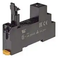


P2RFZ-05-E
Relay Socket, DIN Rail, Screw, 5 Pins, 10 A
- Manufacturer: OMRON INDUSTRIAL AUTOMATION
- Product type: Relay Sockets
- SVHC: To Be Advised
- No. of Pins: 5Pins
- Product Range: -
- Current Rating: 10A
- Voltage Rating: -
- Socket Mounting: DIN Rail
- Socket Terminals: Screw
| Delivery and price | |
|---|---|
| Units per pack | 50 |
| Price | 5.62 € |
| Current stock | 25+ |
| Lead time | 30 days |
CSM_G2R-_-S_(S)_DS_E_2_5

## **General-purpose Relay G2R-** @ **-S (S)**

## **Slim and Space-saving Power Plug-in Relay**

- Reduces wiring work by 60% when combined with the

- P2RF-@-PU Push-In Plus Socket

**==> picture [24 x 14] intentionally omitted <==**

**----- Start of picture text -----**<br>
LR<br>**----- End of picture text -----**<br>


- (according to actual OMRON measurements).

- Lockable test button models available.

- Built-in mechanical operation indicator.

- Provided with nameplate.

- AC type is equipped with a coil-disconnection self-diagnostic function (LED type).

- High switching power (1-pole: 10 A).

For the most recent information on models that have been certified for safety standards, refer to your OMRON website.

## **Model Number Structure**

## **Model Number Legend**

> **G2R -      -** ~~UO~~ **S** ~~UU~~ **(S) 1 2 3 4 5**

## **1. Number of Poles**

- 1: 1 pole

- 2: 2 poles

## **4. Rated Coil Voltage**

## **5. Mechanical operation indicator and Nameplate**

- (S): Models with mechanical operation indicator and Nameplate

## **2. Terminals**

- S: Plug-in

## **3. Classification**

Blank: General-purpose

- N: LED indicator

- D: Diode

- ND: LED indicator and diode

NI: LED indicator with test button NDI: LED indicator and diode with test button

**Note:** Contact your OMRON representative for Relays with gold-plated contacts.

**1**

**G2R-** @ **-S (S)**

**Ordering Information**

**When your order, specify the rated voltage.**

## **List of Models**

|**Classification**|**Coil ratings**|**Contact form**|**Contact form**|
|---|---|---|---|
|||**SPDT**|**DPDT**|
|General-purpose|AC 24, 48, 110, 120, 230, 240<br>DC 6, 12, 24, 48|**G2R-1-S (S)**|**G2R-2-S (S)**|
|LED indicator||**G2R-1-SN (S)**|**G2R-2-SN (S)**|
|LED indicator with test button||**G2R-1-SNI (S)**|**G2R-2-SNI (S)**|
|Diode|DC 6, 12, 24, 48|**G2R-1-SD (S)**|**G2R-2-SD (S)**|
|LED indicator and diode||**G2R-1-SND (S)**|**G2R-2-SND (S)**|
|LED indicator and diode with test button||**G2R-1-SNDI (S)**|**G2R-2-SNDI (S)**|


- **Note: 1.** The standard models are compliant with UL/CSA and VDE standards. Also, an EC compliance declaration has been made for combinations with the P2RF- @ -E, P2RF- @ -S and P2RF- @ -PU. The Relays bear the CE Marking.

   **2.** Refer to _Connecting Sockets_ , below, for applicable Socket models.

   **3.** When ordering, add the rated coil voltage and "(S)" to the model number. Rated coil voltages are given in the coil ratings table. Example: G2R-1-S 12 VDC (S)

Rated coil voltage

**2**

**G2R-** @ **-S (S)**

## **Accessories (Order Separately) Connecting Sockets Track/surface-mounting Socket**

|**Applicable**<br>**relay model*1**|**Mounting**<br>**Method**|**Conductive part**<br>**protection**|**Terminal Type**|**Applicable**<br>**crimp terminal/**<br>**Electric wire**|**Exclusive**<br>**short bar**<br>**(Order Separately)**|**Appearance**|**Model**|
|---|---|---|---|---|---|---|---|
|G2R-1-S|Mounted on a<br>DIN track or<br>with screws|Available|Push-In Plus<br>Terminal|Ferrules<br>Solid wire<br>Stranded wire|Available||**P2RF-05-PU *2**|
||||Screw terminal<br>(M3 screw size)|Forked terminals<br>Solid wire<br>Stranded wire|Available||**P2RFZ-05-E *4**|
|||Option<br>(Terminal cover<br>sold separately)<br>*3|Screw terminal<br>(M3.5 screw size)|Round terminals<br>Forked terminals<br>Solid wire<br>Stranded wire|Available||**P2RFZ-05**|
|||None<br>~~_~~|||None<br>~~a~~||**P2RF-05**<br>Scheduled to be<br>unavailable to order at<br>the end of March 2023|
|G2R-2-S|Mounted on a<br>DIN track or<br>with screws|Available<br>~~_~~|Push-In Plus<br>Terminal|Ferrules<br>Solid wire<br>Stranded wire|Available<br>~~a~~||**P2RF-08-PU *2**|
||||Screw terminal<br>(M3 screw size)|Forked terminals<br>Solid wire<br>Stranded wire|Available||**P2RFZ-08-E *4**|
|||Option<br>(Terminal cover<br>sold separately)<br>*3|Screw terminal<br>(M3.5 screw size)|Round terminals<br>Forked terminals<br>Solid wire<br>Stranded wire|Available||**P2RFZ-08**|
|||None|||None|Sal|**P2RF-08**<br>Scheduled to be<br>unavailable to order at<br>the end of March 2023|


- *1.The applicable relay model is a plug-in terminal type.

- *2.There are screw mounting holes in the DIN hooks on the P2RF-@@-PU. Pull out the DIN hook tabs to mount the Sockets with screws.

- *3.Terminal cover type is P2CZ-Z. (Order Separately) For details, refer to the on page 6.

- *4.The finger-protection type (P2RFZ-@@-E) is a type in which the terminal cover is integrated into the socket. Round terminals cannot be used. Use forked terminals or ferrules instead.

**3**

**G2R-** @ **-S (S)**

## **Back-mounting Socket**

|**Applicable Relay model**|**Mounting Method**|**Appearance**|**Models**|
|---|---|---|---|
|G2R-1-S|PCB terminals||**P2R-05P**|
||||**P2R-057P**|
||Solder terminals||**P2R-05A**|
|G2R-2-S|PCB terminals||**P2R-08P**|
||||**P2R-087P**|
||Solder terminals||**P2R-08A**|


## **For Push-In Plus Terminal Block Sockets**

## **Short Bars**

|**Applicable sockets**|**Pitch**|**Application**|||**Shape/ext**|**ernal dimensions**|**Number of**<br>**poles**|**L (Length)**|**Insulation**<br>**color**|**Short Bars Model*1**|
|---|---|---|---|---|---|---|---|---|---|---|
|**P2RF-05-PU**<br>**P2RF-08-PU**|7.75 mm|Bridging contact<br>terminals<br>(common)||||3.90<br>1.57<br>12<br>18.5|2|15.1|Red (R)<br>Blue (S)<br>Yellow(Y)|**PYDN-7.75-020**@|
||||||~~L~~<br>||||||
||||||||3|22.85||**PYDN-7.75-030**@|
||||||||4|30.6||**PYDN-7.75-040**@|
||||||||20|154.6||**PYDN-7.75-200**@|
|||||2.25|||||||
||15.5 mm|For Coil<br>terminals||2.||3.90<br>1.57<br>12<br>18.5|8|115.55||PYDN-15.5-080@|
||||||25<br>~~115.85~~||||||


*1.Replace the box (@) in the model number with the code for the covering color. @Color selection: R = Red, S = Blue, Y = Yellow

## **Labels**

|**Applicable sockets**|**Model**|
|---|---|
|**P2RF-05-PU**<br>**P2RF-08-PU**|**XW5Z-P4.0LB1**<br>(1 sheet/60 pieces)|


**4**

**G2R-** @ **-S (S)**

## **For Screw Terminal Sockets**

## **Short Bars**

|**Applicable**<br>**sockets**|**Pitch**|**Appearance**|**Dimensions (mm)**|**Number**<br>**of poles**|**Insulation**<br>**color**|**Short Bars Model**|**Maximum**<br>**carry**<br>**current**|**Minimum**<br>**order**<br>**(set)**|
|---|---|---|---|---|---|---|---|---|
|P2RFZ-05-E<br>P2RFZ-08-E|6.8<br>mm||2.9<br>2.5 max.<br>9<br>6.8±0.1<br>15.7±0.1<br>8.7 max.<br>~~152.7 max.~~<br>15.4 max.<br>~~Tat Cate Cat Cate Cat! Gate Cate Ct CAG! Cats~~<br>~~a~~<br>~~—__.|~~<br>~~It~~|20|Blue(S)|**P2DN-6.8-100S**|20 A|1|
||15.7<br>mm||15.7±0.1<br>2.9<br>9<br>2.5 max.<br>8.7 max.<br>15.4 max.<br>~~152.7 max.~~<br>~~Cee~~ ~~a~~|10||**P2DN-15.7-100S**|||
|P2RFZ-05<br>P2RFZ-08|8.5<br>mm||3.4<br>8.5±0.1<br>19.4±0.1<br>2.5 max.<br>16.2 max.<br>10.7<br>8.7 max.<br>~~187.7 max.~~|20|Blue(S)|**P2DN-8.5-100S**|20 A|1|
||19.4<br>mm||19.4±0.1<br>2.5 max.<br>8.7 max.<br>16.2 max.<br>10.7<br>3.4<br>~~187.7 max.~~|10||**P2DN-19.4-100S**|||


- **Note: 1.** Select an applicable type of short bars by checking applicable socket type, appearance, and dimensions.

   **2.** Use the Short Bars for crossover wiring within one Socket or between Sockets.

   **3.** Cannot be used on the P2RF-05, P2RF-08.

   **4.** Use the short bars on the lower section of the socket.

      - When using the short bars on the upper section of the socket, insert them so that their heads are pointed upwards (see the figure below). Otherwise, short bars may interfere with the socket, leading to improper wiring and contact failure.

**==> picture [41 x 22] intentionally omitted <==**

**----- Start of picture text -----**<br>
Upper section<br>Lower section<br>**----- End of picture text -----**<br>


P2RFZ Series P2RFZ-E Series

- One set (order unit) contains 10 short bars and 20 caps.

## **Accessories for Short Bars (P2DN) Cap**

**==> picture [489 x 116] intentionally omitted <==**

**----- Start of picture text -----**<br>
Short Bars Models Appearance Dimensions (mm) Model<br>5.2 max.<br>4 max.<br>P2DN-8.5-100S<br>P2DN-19.4-100S<br>P2DN-CP100<br>P2DN-6.8-100S<br>P2DN-15.7-100S<br>6 max.<br>oe<br>**----- End of picture text -----**<br>


**5** omRon ~~a~~

**G2R-** @ **-S (S)**

## **For Screw Terminal Sockets (P2RFZ-05/P2RFZ-08) Terminal covers**

|**Applicable sockets**|**Appearance**|**Model**|**Minimum order (set)**|
|---|---|---|---|
|P2RFZ-05<br>P2RFZ-08||~~rm~~|**P2CZ-C**<br>~~rm~~||


- **Note: 1.** These covers cannot be used for P2RF-05 and P2RF-08.

   **2.** Use these covers in a combination with P2RFZ-05 and P2RFZ-08.

   **3.** Do not install short bars (optional) on the upper section (see the figure below). Short bars may interfere with the terminal cover, making the terminal cover unusable.

**==> picture [113 x 47] intentionally omitted <==**

**----- Start of picture text -----**<br>
Upper section<br>Lower section<br>P2RFZ Series<br>**----- End of picture text -----**<br>


## **Dimensions with terminal cover**

## **P2RFZ-05**

**==> picture [142 x 105] intentionally omitted <==**

**----- Start of picture text -----**<br>
1.5<br>71.5 max.<br>Be |<br>4.2 1 35.5 max.<br>19.5 max.<br>54 max.<br>**----- End of picture text -----**<br>


**==> picture [43 x 8] intentionally omitted <==**

**----- Start of picture text -----**<br>
P2RFZ-08<br>**----- End of picture text -----**<br>


**==> picture [134 x 105] intentionally omitted <==**

**----- Start of picture text -----**<br>
1 1.5<br>71.5 max. hao<br>4.2 1 35.5 max.<br>19.5 max.<br>54 max.<br>**----- End of picture text -----**<br>


## **Labels**

|**Applicable sockets**|**Model**|**Minimum order (sheet)**<br>**(quantity per sheet)**|
|---|---|---|
|P2RFZ-@-E|**XW5Z-P2.5LB1**|5<br>1 sheet (72 pieces)|


**Note:** This label cannot be applied on sockets other than P2RFZ-@-E.

## **Mounting Tracks**

|**Applicable Socket**|**Description**|**Description**|**Model**|**Minimum order**<br>**(quantity)**|
|---|---|---|---|---|
|Track-connecting Socket<br>Mounting track<br>End plate *1<br>Spacer|Mounting track|50 cm (l) × 7.3 mm (t):|**PFP-50N**|---|
|||1 m (l) × 7.3 mm (t):|**PFP-100N**||
|||1 m (l) × 16 mm (t):|**PFP-100N2**||
||End plate *1||**PFP-M**|10|
||Spacer||**PFP-S**||
|Back-connectingSocket<br>Mountin|Mountingplate *2||**P2R-P**|1|


- *1.When mounting DIN rail, please use End Plate (PFP-M).

- *2.Used to mount several P2R-05A and P2R-08A Connecting Sockets side by side.

**6** omrROnNn ~~a~~

**G2R-** @ **-S (S)**

**Specifications**

## **Coil Ratings**

|**Rated voltage**|**Rated voltage**|**Rated current***|**Rated current***|**Coil**<br>**resistance**|**Coil inductance (H)**<br>**(ref. value)**|**Coil inductance (H)**<br>**(ref. value)**|**Must**<br>**operate**<br>**voltage**|**Must**<br>**release**<br>**voltage**|**Max.**<br>**voltage**|**Power**<br>**consumption**<br>**(approx.)**|
|---|---|---|---|---|---|---|---|---|---|---|
|||**50 Hz**|**60 Hz**||**Armature**<br>**OFF**|**Armature**<br>**ON**|**% of rated voltage**||||
|**AC**|**24 V**|43.5 mA|37.4 mA|253Ω|0.81|1.55|80% max.|30% max.|110%|0.9 VA at 60 Hz|
||**48 V**|21.8 mA|18.8 mA|1,040Ω|3.12|6.17|||||
||**110 V**|9.5 mA|8.2 mA|5,566Ω|13.33|26.83|||||
||**120 V**|8.6 mA|7.5 mA|7,286Ω|16.13|32.46|||||
||**230 V**|4.4 mA|3.8 mA|27,172Ω|72.68|143.90|||||
||**240 V**|4.2 mA|3.7 mA|27,800Ω|90.58|182.34|||||
||||||||||||
|**Rated voltage**||**Rated current***||**Coil**<br>**resistance**|**Coil inductance (H)**<br>**(ref. value)**||**Must**<br>**operate**<br>**voltage**|**Must**<br>**release**<br>**voltage**|**Max.**<br>**voltage**|**Power**<br>**consumption**<br>**(approx.)**|
||||||**Armature**<br>**OFF**|**Armature**<br>**ON**|**% of rated voltage**||||
|**DC**|**6 V**|87.0 mA||69Ω|0.25|0.48|70% max.|15% min.|110%|0.53 W|
||**12 V**|43.2 mA||278Ω|0.98|2.35|||||
||**24 V**|21.6 mA||1,113Ω|3.60|8.25|||||
||**48 V**|11.4 mA||4,220Ω|15.2|29.82|||||


- **Note: 1.** The rated current and coil resistance are measured at a coil temperature of 23°C with tolerances of +15%/-20% for the AC rated current and ±10% for the DC coil resistance.

   **2.** The AC coil resistance and inductance values are reference values only (at 60 Hz).

   **3.** Operating characteristics were measured at a coil temperature of 23°C.

   **4.** The maximum voltage is the maximum possible value of the voltage that can be applied to the relay coil. It is not the maximum voltage that can be applied continuously.

## **Contact Ratings**

|**Contact Ratings**|||||
|---|---|---|---|---|
|**Number of poles**|1 pole||2 poles||
|**Load**|Resistive load<br>(cosφ= 1)|Inductive load<br>(cosφ= 0.4; L/R = 7 ms)|Resistive load<br>(cosφ= 1)|Inductive load<br>(cosφ= 0.4; L/R = 7 ms)|
|**Rated load**|10 A at 250 VAC;<br>10 A at 30 VDC|7.5 A at 250 VAC;<br>5 A at 30 VDC|5 A at 250 VAC;<br>5 A at 30 VDC|2 A at 250 VAC; 3 A at<br>30 VDC|
|**Rated carry current**|10 A||5 A||
|**Max. switching voltage**|440 VAC, 125 VDC||380 VAC, 125 VDC||
|**Max. switching current**|10 A||5 A||
|**Max. switching power**|2,500 VA,<br>300 W|1,875 VA,<br>150 W|1,250 VA,<br>150 W|500 VA,<br>90 W|
|**Failure rate (reference value) ***|100 mA at 5 VDC||10 mA at 5 VDC||


**Note:** P level: λ 60 = 0.1 x 10[-6] /operation

- *This value was measured at a switching frequency of 120 operations per minute.

**7**

**G2R-** @ **-S (S)**

## **Characteristics**

|**Item**|**1 pole**|**2 poles**|
|---|---|---|
|**Contact configration**|SPDT||
|**Contact structure**|Single||
|**Contact resistance**|100 mΩmax.||
|**Operate (set) time**|15 ms max.||
|**Release (reset) time**|AC: 10 ms max.; DC: 5 ms max.<br>(w/built-in diode: 20 ms max.)|AC: 15 ms max.; DC: 10 ms max.<br>(w/built-in diode: 20 ms max.)|
|**Max. operating**<br>**frequency**|Mechanical:<br>18,000 operations/hr<br>Electrical:<br>1,800 operations/hr (under rated load)||
|**Insulation resistance**|1,000 MΩmin. (at 500 VDC)||
|**Dielectric strength ***|5,000 VAC, 50/60 Hz for 1 min between coil and<br>contacts;<br>1,000 VAC, 50/60 Hz for 1 min between contacts of<br>same polarity|5,000 VAC, 50/60 Hz for 1 min between coil and contacts;<br>3,000 VAC, 50/60 Hz for 1 min between contacts of different polarity<br>1,000 VAC, 50/60 Hz for 1 min between contacts of same polarity|
|**Vibration resistance**|Destruction:<br>10 to 55 to 10 Hz, 0.75 mm single amplitude (1.5 mm double amplitude)<br>Malfunction:<br>10 to 55 to 10 Hz, 0.75 mm single amplitude (1.5 mm double amplitude)||
|**Shock resistance**|Destruction:<br>1,000 m/s2<br>Malfunction:<br>200 m/s2when energized; 100 m/s2when not energized||
|**Endurance**|Mechanical:<br>AC coil: 10,000,000 operations min.;<br>DC coil: 20,000,000 operations min. (at 18,000 operations/hr)<br>Electrical:<br>100,000 operations min. (at 1,800 operations/hr under rated load)||
|**Ambient temperature**|Operating:<br>–40°C to 70°C (with no icingor condensation)||
|**Ambient humidity**|Operating:<br>5% to 85%||
|**Weight**|Approx. 20g||


**Note:** Values in the above table are the initial values.

*These values are relay only. Prease refer to the “Products Related to Common Sockets and DIN Tracks Data Sheet” for connecting sockets.

## **Approved Standards UL 508 (File No. E41643)**

|**Model**|**Contact**<br>**form**|**Coil ratings**|**Contact ratings**|**Opera-**<br>**tions**|
|---|---|---|---|---|
|G2R-1-S (S)|SPDT|5 to 110 VDC<br>6 to 240 VAC|10 A, 30 VDC (resistive)<br>10 A, 250 VAC (general use)|100 × 103|
||||TV-3 (NO contact only)|25 × 103|
|G2R-2-S (S)|DPDT||5 A, 30 VDC (resistive)<br>5 A, 250 VAC (general use)|100 × 103|
||||TV-3 (NO contact only)|25 × 103|


## **CSA 22.2 No.0, No.14 (File No. LR31928)**

|**Model**|**Contact**<br>**form**|**Coil ratings**|**Contact ratings**|**Opera-**<br>**tions**|
|---|---|---|---|---|
|G2R-1-S (S)|SPDT|5 to 110 VDC<br>6 to 240 VAC|10 A, 30 VDC (resistive)<br>10 A, 250 VAC (general use)|100 × 103|
||||TV-3 (NO contact only)|25 × 103|
|G2R-2-S (S)|DPDT||5 A, 30 VDC (resistive)<br>5 A, 250 VAC (general use)|100 × 103|
||||TV-3 (NO contact only)|25 × 103|


## **IEC/VDE (Certificate No. 40015012 EN 61810-1)**

|**Contact**<br>**form**|**Coil ratings**|**Contact ratings**|**Operations**|
|---|---|---|---|
|1 pole|6, 12, 24, 48 VDC<br>24, 110, 120, 230,<br>240 VAC|5 A, 440 VAC (cosφ= 1.0)<br>10 A, 250 VAC (cosφ= 1.0)<br>10 A, 30 VDC (0 ms)|100 × 103|
|2 poles|6, 12, 24, 48 VDC<br>24, 110, 120, 230,<br>240 VAC|5 A, 250 VAC (cosφ=1.0)<br>5 A, 30 VDC (0 ms)|100 × 103|


## **LR**

|**Number**<br>**of poles**|**Coil ratings**|**Contact ratings**|**Operations**|
|---|---|---|---|
|1 pole|5 to 110 VDC<br>6 to 240 VDC|10 A, 250 VAC (general use)<br>7.5 A, 250 VAC (PF0.4)<br>10 A, 30 VDC (resistive)<br>5A, 30VDC (L/R=7ms)|100 × 103|
|2 poles|5 to 110 VDC<br>6 to 240 VDC|5 A, 250 VAC (general use)<br>2 A, 250 VAC (PF0.4)<br>5 A, 30 VDC (resistive)<br>3A, 30VDC (L/R=7ms)|100 × 103|


**8**

**G2R-** @ **-S (S)**

**Engineering Data**

## **Maximum Switching Power**

**==> picture [325 x 548] intentionally omitted <==**

**----- Start of picture text -----**<br>
G2R-1-S (S) G2R-2-S (S)<br>100 100<br>= AC inductive load (cosφ = 0.4) it AC resistive load l || A<br>AC inductive load<br>10 10 (cosφ = 0.4) AC resistive  load<br>DC resistive<br>=2Sei load AW alll SihSSS DC resistive   —<br>LT DC inductive load   Tn ANIL tf HT] r_| load NANT<br>1 (L/R = 7 ms) 1 DC inductive load<br>ARG HO \ONG<br>(L/R = 7 ms)<br>a| — enh Fee<br>mA Soo oh oe<br>0.11 a 10 100 1000 0.11 rrr 10 CT 100 1000<br>Switching voltage (V) Switching voltage (V)<br>Endurance<br>G2R-1-S (S) G2R-2-S (S)<br>5,000 A 10,000 SS<br>5,000<br>Ree REE<br>250-VAC/30-VDC<br>1,000 Renee resistive load i<br>1,000<br>500 250-VAC inductive load  30-VDC inductive load (L/R = 7ms)<br>. ys (cosφ = 0.4) 500 1<br>250-VAC/30-VDC<br>CONRAN PRS resistive load —<br>10050 | 30-VDC inductive load (L/R = 7ms) UNS 100 250-VAC  RNa ee<br> 50 inductive load<br>(cosφ = 0.4)<br>SEeaeaataaoBERRRRERREEEE esa WEPETE———eccecs<br>0 2 4° 5 6 8 10 12 14 0 J 2 3 4 5<br>Switching current (A) Switching current (A)<br>Ambient Temperature vs Maximum Coil Voltage<br>SERRRRREEE200<br>DC coil<br>oe<br>TN AC coil T<br>5 20 30 40 50 60 70 8 90 106<br>Ambient temperature (°C)<br>Switching current (A) Switching current (A)<br> operations)<br>3  operations)<br>Endurance (x10 3<br>Endurance (x10<br>Maximum voltage (%)<br>**----- End of picture text -----**<br>


## **Endurance**

## **Ambient Temperature vs Maximum Coil Voltage**

**9**

**G2R-** @ **-S (S)**

**(Unit: mm)**

## **Dimensions**

**Note:** All units are in millimeters unless otherwise indicated.

## **SPDT Relays**

**G2R-1-S (S), G2R-1-SN (S), G2R-1-SNI (S) G2R-1-SD (S), G2R-1-SND (S), G2R-1-SNDI (S)**

**==> picture [248 x 184] intentionally omitted <==**

**----- Start of picture text -----**<br>
29 max. 13 max.<br>[Lo of<br>a nn<br>0.5 4.75<br>5.2 5.2<br>17.5<br>DC24V<br>max.<br>20 35.5<br>5<br>1<br>.5<br>7<br>**----- End of picture text -----**<br>


**Terminal Arrangement/Internal Connections (Bottom View)**

**==> picture [217 x 231] intentionally omitted <==**

**----- Start of picture text -----**<br>
G2R-1-S (S) G2R-1-SD (S) (DC)<br>1 1<br>a oe<br>5 2 4 3 5 2 4 3<br>G2R-1-SN (S), G2R-1-SNI (S) (AC) G2R-1-SN (S), G2R-1-SNI (S) (DC)<br>1 1<br>5 2 4 3 5 2 4 3<br>G2R-1-SND (S), G2R-1-SNDI (S) (DC)<br>o r A 1 T<br>5 2 4 3<br>HAT<br>**----- End of picture text -----**<br>


## **DPDT Relays**

**G2R-2-S (S), G2R-2-SN (S), G2R-2-SNI (S) G2R-2-SD (S), G2R-2-SND (S), G2R-2-SNDI (S)**

**==> picture [217 x 79] intentionally omitted <==**

**----- Start of picture text -----**<br>
Terminal Arrangement/Internal Connections<br>(Bottom View)<br>G2R-2-S (S) a 1 e 2 3 4 G2R-2-SD (S) (DC)<br>1 2 3 4<br>8 OT 7 6 5<br>8 7 6 5<br>**----- End of picture text -----**<br>


1 2 3 4 29 max. 13 max. 1 2 3 4 ee ~~os a~~ 8 ~~OT~~ 7 6 5 8 7 6 5 **G2R-2-SN (S), G2R-2-SNI (S) (AC) G2R-2-SN (S), G2R-2-SNI (S) (DC)** 1 2 3 4 1 2 3 4 0.5 2.5 8 7 6 5 8 7 6 5 2.4 wl ~~ee ied ie~~ **G2R-2-SND (S), G2R-2-SNDI (S) (DC)** 5 5 19.4 1 2 3 4 8 7 6 5 ~~ite~~

**10** omRON ~~a~~

**G2R-** @ **-S (S)**

## **Accessories (Order Separately) Socket Characteristics**

|**Model**|**Continuous**<br>**carry current**|**Dielectric strength**|**Insulation**<br>**resistance***|**Remarks**|
|---|---|---|---|---|
|P2RF-05-PU|10 A|Between contact terminals of same polarity: 1,000 VAC for 1 min|1,000 MΩmin.||
|||Between coil and contact terminals: 4,000 VAC for 1 min|||
|P2RF-08-PU|6 A|Between contact terminals of different polarity: 3,000 VAC for 1 min|1,000 MΩmin.||
|||Between contact terminals of same polarity: 1,000 VAC for 1 min|||
|||Between coil and contact terminals: 4,000 VAC for 1 min|||
|P2RFZ-05(-E)|10 A|Between contact terminals of same polarity: 1,000 VAC for 1 min|1,000 MΩmin.||
|||Between coil and contact terminals: 4,000 VAC for 1 min|||
|P2RFZ-08(-E)|6 A|Between contact terminals of different polarity: 3,000 VAC for 1 min|1,000 MΩmin.||
|||Between contact terminals of same polarity: 1,000 VAC for 1 min|||
|||Between coil and contact terminals: 4,000 VAC for 1 min|||
|P2RF-05|10 A|Between contact terminals of same polarity: 1,000 VAC for 1 min|1,000 MΩmin.||
|||Between coil and contact terminals: 4,000 VAC for 1 min|||
|P2RF-08|5 A|Between contact terminals of different polarity: 3,000 VAC for 1 min|1,000 MΩmin.||
|||Between contact terminals of same polarity: 1,000 VAC for 1 min|||
|||Between coil and contact terminals: 4,000 VAC for 1 min|||
|P2R-05P|10 A|Between contact terminals of same polarity: 1,000 VAC for 1 min|1,000 MΩmin.||
|||Between coil and contact terminals: 4,000 VAC for 1 min|||
|P2R-08P|5 A|Between contact terminals of different polarity: 3,000 VAC for 1 min|1,000 MΩmin.||
|||Between contact terminals of same polarity: 1,000 VAC for 1 min|||
|||Between coil and contact terminals: 4,000 VAC for 1 min|||
|P2R-057P|10 A|Between contact terminals of same polarity: 1,000 VAC for 1 min|1,000 MΩmin.||
|||Between coil and contact terminals: 5,000 VAC for 1 min|||
|P2R-087P|5 A|Between contact terminals of different polarity: 3,000 VAC for 1 min|1,000 MΩmin.||
|||Between contact terminals of same polarity: 1,000 VAC for 1 min|||
|||Between coil and contact terminals: 5,000 VAC for 1 min|||
|P2R-05A|10 A|Between contact terminals of same polarity: 1,000 VAC for 1 min|1,000 MΩmin.||
|||Between ground terminals: 1,500 VAC for 1 min|||
|||Between coil and contact terminals: 4,000 VAC for 1 min|||
|P2R-08A|5 A|Between contact terminals of different polarity: 3,000 VAC for 1 min|1,000 MΩmin.||
|||Between contact terminals of same polarity: 1,000 VAC for 1 min|||
|||Between ground terminals: 1,500 VAC for 1 min|||
|||Between coil and contact terminals: 4,000 VAC for 1 min|||


- The insulation resistance was measured with a 500-VDC insulation resistance meter at the same places as those used for measuring the dielectric strength.

**11**

**G2R-** @ **-S (S)**

## **Track/Surface Mounting Sockets**

## **P2RF-05-PU**

**==> picture [402 x 244] intentionally omitted <==**

**----- Start of picture text -----**<br>
57.5<br>Terminal Arrangement/<br>Internal Connection Diagram<br>(Top View)<br>53.1 A2 A1 Mounting Hole<br>30.8 Dimensions<br>(1) (5)<br>28.1<br>(4.2) 25.6<br>Insertion hole  Two M3 screw<br>for short bars  holes or<br>(coil) two 3.5-dia. holes<br>108<br>90 35.3 Release lever<br>12<br>(2)<br>14<br>Insertion hole<br>for short bars  27.35 (3)<br>11<br>(contact) ae (4)<br>Note:  Pull out the hooks to<br>15.5 (4.2) 3.9 25.6 Note: 1. The numbers in parentheses are  mount the Socket with screws.<br>34.3 traditionally used<br>43 terminal numbers.<br>52.1<br>2. Insert the short bar<br>into only the A1 or<br>A2 side.<br>**----- End of picture text -----**<br>


**==> picture [507 x 261] intentionally omitted <==**

**----- Start of picture text -----**<br>
P2RF-08-PU 57.5<br>Terminal Arrangement/<br>Internal Connection Diagram<br>53.1 (Top View)<br>30.8 A2 A1 Mounting Hole<br>28.1 Dimensions<br>(1) (8)<br>(4.2) 25.6<br>Insertion hole<br>for short bars<br>Two M3 screw<br>(coil) holes or<br>two 3.5-dia. holes<br>90 35.3 Release lever 108<br>12 22<br>Insertion hole  (2) (7)<br>for short bars  27.35 14 24<br>(contact) (4) (5)<br>oe 11 21<br>(4.2) 3.9 25.6 (3) (6) Note:  Pull out the hooks to<br>15.5 34.3 mount the Socket<br>43 Note: 1. The numbers in  with screws.<br>52.1 parentheses are<br>traditionally used<br>terminal numbers.<br>2. Insert the short bar<br>into only the A1 or<br>A2 side.<br>**----- End of picture text -----**<br>


**Accessories for P2RF-** @ **-PU No. of Maximum Short Bars Application Pitch poles L (Length) Colors Model**[*] **carry current PYDN-7.75-** @@ **(7.75 mm)** 2 15.1 **PYDN-7.75-020** @ 3.90 ~~L~~ For Contact 3 22.85 **PYDN-7.75-030** @ 18.5 (common)terminals 7.75 mm 4 30.6 Blue (S)Red (R) **PYDN-7.75-040** @ 20 A 12 20 154.6 Yellow (Y) **PYDN-7.75-200** @ For Coil 15.5 mm 8 115.85 **PYDN-15.5-080** @ ~~ae~~ 2.25 1.57 ~~==(=F~~ terminals * Replace the box (@) in the model number with the code for the covering color. **PYDN-15.5-080** @ **(15.5 mm)** 3.90 **Note: 1.** Use the Short Bars for crossover wiring within one Socket or between Sockets. ~~115.85~~ **2.** When using short bar to coil terminals of PYF-@@-PU, make sure to use PYDN-31.0080@ (31 mm). 12 18.5 When using short bar to coil terminals of P2RF-@@-PU, make sure to use PYDN-15.5080@ (15.5 mm). 2.25 1.57

**12** omrRon ~~a~~

**G2R-** @ **-S (S)**

**P2RFZ-05-E**

## **P2RFZ-08-E**

**==> picture [412 x 390] intentionally omitted <==**

**----- Start of picture text -----**<br>
Terminal Arrangement/ Mounting Hole<br>Internal Connection Diagram Dimensions<br>6 (Top View)<br>3.2-dia. hole<br>4<br>5-M3X8 48 max. 2 10.5<br>2<br>3<br>39.5±0.1<br>(42.3)<br>39.5<br>M3 or<br>78.5 max. | : in : cs  a it 3.5-dia.<br>hole<br>(35.8)<br>3.5-dia.  5 1<br>hole Le? : 35.5<br>17.2<br>4<br>31 max.<br>16 max.<br>eee 61 max.<br>Terminal Arrangement/ Mounting Hole<br>Internal Connection Diagram Dimensions<br>6<br>(Top View) 3.2-dia. hole<br>10.5<br>8-M3X8 48 max. 2 6 3<br>2 7 2<br>5 4<br>39.5±0.1<br>(42.3)<br>39.5<br>M3 or<br>78.5 max. 3.5-dia.<br>hole<br>3.5-dia.  (35.8) 8 1<br>hole 2 oa 35.5<br>17.2<br>4 S| TS<br>31 max.<br>16 max.<br>61 max.<br>**----- End of picture text -----**<br>


## **P2RFZ-05**

## **P2RFZ-08**

**==> picture [411 x 284] intentionally omitted <==**

**----- Start of picture text -----**<br>
7 Terminal Arrangement/ Mounting Hole<br>5-M3.5×8 1.5  Internal Connection Diagram Dimensions<br>Ly 7 4 dia. (Top View)<br>4.2-dia. hole<br>39.5 4<br>30 3 9.5<br>71.5 max. 35.5<br>Fl ay C4 13.8 2 ] 30 [±0.1] aa<br>il ly” To | ||<br>2<br>5 1 M3 or 3.2-dia. hole<br>4.2 1 26.5 max. Recommended<br>19.5 max. mounting screw:<br>54 max. M3 × 16 mm or larger<br>1 7 8-M3.5×8 1.5  Internal Connection DiagramTerminal Arrangement/(Top View) Mounting Hole Dimensions<br>4 dia.<br>may — 4.2-dia. hole<br>39.5 6 3 9.5<br>30 5 4<br>71.5 max. 35.5 30 [±0.1]<br>13.8<br>7 2 M3 or 3.2-dia. hole<br>8 1 Recommended<br>4.2 1 26.5 max. mounting screw:<br>19.5 max. M3 × 16 mm or larger<br>54 max.<br>**----- End of picture text -----**<br>


**13** omRON ~~a~~

**G2R-** @ **-S (S)**

**==> picture [486 x 324] intentionally omitted <==**

**----- Start of picture text -----**<br>
P2RF-05 7 2 Terminal Arrangement Mounting Holes<br>Five, M3.5 x 8 (Top View) (for Surface Mounting)<br>4-dia. holes 4.2-dia. hole<br>71.5 max. 35.5<br>30 0.05<br>4 19.5 M3 or 3.2-dia.<br>19.5 max. 30 max.<br>hole<br>wr: 54 max. al Recommended<br>mounting screw:<br>M3 × 16 mm or<br>larger<br>=i<br>P2RF-08<br>2<br>7<br>Eight, M3.5 x 8 Terminal Arrangement Mounting Holes<br>4-dia. holes (Top View) (for Surface Mounting)<br>com Z<br>4.2-dia. hole<br>71.5 max. 35.5<br>30 0.05<br>19.5<br>4 + aii<br>19.5 max. 30 max. M3 or 3.2-dia.<br>54 max. hole<br>Recommended<br>mounting screw:<br>M3 × 16 mm or<br>larger<br>iit<br>**----- End of picture text -----**<br>


**14** omRON ~~a~~

**G2R-** @ **-S (S)**

## **Mounting Height of Relay with Track/Surface Mounting Sockets**

**==> picture [179 x 77] intentionally omitted <==**

**----- Start of picture text -----**<br>
P2RF-05-PU G2R-@-S (S)<br>Relay<br>P2RF-05-PU<br>Socket<br>63.6<br>**----- End of picture text -----**<br>


**==> picture [54 x 7] intentionally omitted <==**

**----- Start of picture text -----**<br>
P2RF-08-PU<br>**----- End of picture text -----**<br>


**==> picture [189 x 118] intentionally omitted <==**

**----- Start of picture text -----**<br>
G2R-@-S (S)<br>Relay<br>P2RF-08-PU<br>Socket<br>63.6<br> 28.1<br> (3.9)<br>**----- End of picture text -----**<br>


**==> picture [219 x 29] intentionally omitted <==**

**----- Start of picture text -----**<br>
 28.1   28.1<br>**----- End of picture text -----**<br>


**==> picture [32 x 25] intentionally omitted <==**

**----- Start of picture text -----**<br>
 (3.9)<br>**----- End of picture text -----**<br>


## **P2RFZ-05**

## **P2RFZ-08**

**==> picture [165 x 101] intentionally omitted <==**

**----- Start of picture text -----**<br>
G2R-@-S<br>54 54.5<br>58 *<br>57.5 *<br>**----- End of picture text -----**<br>


**==> picture [165 x 101] intentionally omitted <==**

**----- Start of picture text -----**<br>
G2R-@-S<br>54 54.5<br>58 *<br>57.5 *<br>**----- End of picture text -----**<br>


## **P2RFZ-** @ **-E**

**==> picture [35 x 7] intentionally omitted <==**

**----- Start of picture text -----**<br>
P2RF- @<br>**----- End of picture text -----**<br>


**==> picture [336 x 109] intentionally omitted <==**

**----- Start of picture text -----**<br>
G2R-@-S (S)  G2R-@-S (S)<br>Relay Relay<br>P2RFZ-@-E<br>Socket P2RF-@<br>Socket<br>67.0 62.0<br>70.5 * 66.5 *<br>**----- End of picture text -----**<br>


*These are values when using the DIN track PFP-@N. Heights become higher by approximately 9 mm when using PFP-@N2.

**15**

**G2R-** @ **-S (S)**

## **Back-connecting Sockets**

**==> picture [472 x 642] intentionally omitted <==**

**----- Start of picture text -----**<br>
P2R-05P (1-pole) Terminal Arrangement Mounting Holes<br>(Bottom View) (Bottom View)<br>14.5 max. Tolerance: ±0.1<br>1 4 7<br>4<br>Five,<br>6 1.6-dia.<br>4.5 6 holes<br>15 35.5 max.<br>1.2 4.5<br>4 15<br>3.5<br>1.5 4<br>(5)<br>26Li a<br>7 4<br>7<br>36.5 max.<br>P2R-08P (2-pole)<br>Terminal Arrangement Mounting Holes<br>4 14.5 max. (Bottom View) (Bottom View)<br>7<br>0.3<br>7.5 Eight, 1.3-dia. holes<br>5<br>5<br>35.5 max. 5<br>20<br>1 5<br>2.8 20<br>1.5<br>(4.3)<br>7.5<br>t Terminal plate thickness: 0.3 36.5 max. l<br>4.5<br>P2R-05A (1-pole) 7.5 14.5 max.<br>1.2<br>0.3<br>Terminal Arrangement<br>6.7 (Bottom View)<br>3.8<br>16.7 5 35.5 max.<br>Panel Cutout<br>Five, 3 x 1.8-dia. holes (Bottom View)<br>2S<br>13.6 0.1<br>6<br>Terminal plate thickness: 0.3 36.5 max.<br>30.5 0.2<br>P2R-08A (2-pole) 6.5 7.5 14.5 max.<br>1.2<br>0.3<br>5<br>5<br>20 35.5 max. Recommended thickness of<br>2.6 the panel is 1.6 to 2.0 mm<br>2.8<br>1.5<br>Eight, 3 x 1.2-dia. holes<br>7.5<br>Terminal plate thickness: 0.3 LS 36.5 max.<br>**----- End of picture text -----**<br>


**16**

**G2R-** @ **-S (S)**

**==> picture [455 x 251] intentionally omitted <==**

**----- Start of picture text -----**<br>
P2R-057P (1-pole) 14 max.8.7 110.46.4 3.5 Terminal Arrangement(Bottom View) Mounting Holes(Bottom View)<br>0.7 1 1 4 0.1 Five,<br>1.6-dia.<br>6 holes<br>37 max.29.6 4.515 6 0.1<br>4<br>1 8.75 4.5 0.1 15 0.1<br>8.7 7.4 4 0.1<br>5<br>7 0.1<br>41 max.<br>el :<br>P2R-087P (2-pole) 14 max. 16.4 Terminal Arrangement Mounting Holes<br>7.5 10.4 3.5 (Bottom View) (Bottom View)<br>_ 1 0.3 7.5 Eight, 1.3-dia.<br>5 holes<br>5<br>37 max.29.1 1 20 5<br>5<br>8.1<br>20<br>8.9 7.4<br>(8.1)<br>y SF 41 max. -|-J te<br>**----- End of picture text -----**<br>


## **Mounting Height of Relay with Back-connecting Sockets**

**==> picture [368 x 80] intentionally omitted <==**

**----- Start of picture text -----**<br>
P2R- @ P P2R- @ A P2R- @ 7P<br>G2R-@-S (S) Relay<br>G2R-@-S (S) Relay<br>44.5 47.5 G2R-@-S (S) Relay<br>P2R-@P  38.0<br>P2R-@A<br>Socket Socket P2R-@7P<br>Socket<br>y | Ii<br>**----- End of picture text -----**<br>


**17** omrRon ~~a~~

**G2R-** @ **-S (S)**

## **Mounting Tracks**

**==> picture [507 x 111] intentionally omitted <==**

**----- Start of picture text -----**<br>
PFP-100N, PFP-50N PFP-100N2<br>16<br>—— 7.3±0.15 ———<br>4.5<br>4.5<br>35±0.3 27±0.15 35±0.3 27 24 29.2<br>feetasl 15 25 10 251,000 (500) 25 10 25 15 (5) 1 15 25 10 25 1,000 25 10 25 15 Tob 1 1.5<br>**----- End of picture text -----**<br>


It is recommended to use a panel 1.6 to 2.0 mm thick.

## **End Plate**

**==> picture [233 x 95] intentionally omitted <==**

**----- Start of picture text -----**<br>
PFP-M 10<br>6.2<br>1.8<br>1<br>50 35.5 35.3<br>1.8<br>11.5 1.3<br>10<br>M4 x 8 pan  4.8<br>head screw<br>**----- End of picture text -----**<br>


## **Spacer**

**==> picture [214 x 97] intentionally omitted <==**

**----- Start of picture text -----**<br>
16<br>PFP-S 5 12<br>34.8<br>44.3<br>16.5<br>**----- End of picture text -----**<br>


## **Mounting Plate**

## **P2R-P**

**==> picture [193 x 98] intentionally omitted <==**

**----- Start of picture text -----**<br>
90<br>R2.25 4.5 13.6<br>10-Ellipse hole<br>3.4<br>49 42 [±0.1] 30.5<br>(fata<br>Square hole eeeie 18 [±0.15] 18 [±0.15] 18 [±0.15] 18 [±0.15]<br>9 [±0.1] 72 [±0.2] 9 [±0.1] t=1.6 mm<br>**----- End of picture text -----**<br>


**18**

**G2R-** @ **-S (S)**

## **Safety Precautions**

**Be sure to read the** _**Common Precautions for All Relay**_ **in the website at the following URL: http://www.ia.omron.com/.**

**Refer to** _**Products Related to Common Sockets and DIN Tracks**_ **for precautions on the applicable Sockets. Refer to** _**PYF-**_ @@ _**-PU/P2RF-**_ @@ _**-PU**_ **for precautions on Push-In Plus Terminal Block Sockets. Warning Indications** • Use the following wire diameters as a guide for wiring. (Select the appropriate wire diameter for the current used.) **Indicates a potentially hazardous CAUTION situation which, if not avoided, may result Model Recommended wire diameter (mm[2] ) in minor or moderate injury or in property** 0.75 to 2.5 mm[2] Stranded wire **damage.** P2RF-05 AWG 18 to 14 **Supplementary comments on what to do** P2RF-08 0.75 to 2.0 mm[2] **Precautions for or avoid doing to prevent failure to** Solid wire AWG 18 to 14 **Correct Use operate, malfunction, or undesirable effects on product performance.** P2RFZ-05-E Stranded wire 0.75 to 2.5 mm[2] P2RFZ-08-E AWG 18 to 14 P2RF-05-E 0.75 to 1.5 mm[2] **Cation** P2RF-08-E Solid wire AWG 18 to 16 ~~—==~~ • Do not use the test button for any purpose other than testing. Be sure not to touch the test button accidentally as this will turn the **Using a short-circuit bar** contacts ON. Before using the test button, confirm that circuits, the • Use the short-circuit bar that is suitable for the socket you are using load, and any other connected item will operate safely. and the location of use.

   - **Using a short-circuit bar** • Use the short-circuit bar that is suitable for the socket you are using and the location of use.

   - Note that the P2DN short-circuit bar for the P2RFZ-E Socket has both a short-circuit bar for shorting coil terminals and a short-circuit bar for shorting contact COM terminals.

- Check that the test button is released before turning ON relay circuits.

- If the test button is pulled out too forcefully, it may bypass the momentary testing position and go straight into the locked position.

   - The short-circuit bar can be cut to match any number of poles. Cut with a tool as appropriate for the number of relays and sockets. When using a cut short-circuit bar, take care to avoid injuring yourself on the cut surface.

- Use an insulated tool when you operate the test button.

## **Precautions for Correct Use**

- When cutting with a tool, insert the tool from the plastic part and cut along the slot in the plastic part between terminals. If you cut a part other than the slot in the plastic part between terminals, it may not be possible to attach the insulating cap.

## **About the Built-in Diodes**

The diodes that are built into the Relays are designed to absorb reverse voltage from the Relay’s coil. If a large surge in voltage is applied to the diode from an external source, the element will be destroyed.

If there is the possibility of large voltage surges that could be applied to the elements from an external source, take any necessary surge absorption measures.

## **Latching Levers**

- Turn OFF the power supply when operating the latching lever. After you use the latching lever always return it to its original state.

- Do not use the latching lever as a switch.

- The latching lever can be used for 100 operations minimum.

## **Relay Replacement**

To replace the Relay, turn OFF the power supply to the load and Relay coil sides to prevent unintended operation and possible electrical shock.

• When using a cut short-circuit bar (P2DN), always use the provided cap to protect the charger part.

## **Coil tape color**

Pink tape is used for the AC coil type and blue tape is used for the DC coil type, making it easy to distinguish AC and DC.

## **Screw terminal socket**

• Use the following tightening torque for screws during wiring.

|**Model**<br>~~—_~~|**Tightening torque**<br>~~—_~~|
|---|---|
|P2RF-05<br>P2RF-08<br>~~—_~~|0.78 to 1.18 N⋅m<br>~~—_~~|
|P2RFZ-05-E<br>P2RFZ-08-E<br>P2RF-05-E<br>P2RF-08-E<br>~~—_~~|0.59 to 0.88 N⋅m<br>*Use a No. 1 screwdriver.<br>~~—_~~|


- Use the short-circuit bar to short-circuit two or more coil terminals, or two or more contact COM terminals.

- Do not use a deformed short-circuit bar. Risk of failure, malfunctioning, or deterioration of characteristics.

- In socket terminals, insert the short-circuit bar in the correct orientation all the way into all terminals, and then secure with screws.

- Install the short -circuit bar before wiring.

## **Common connection method when using a short bar**

- When connecting the P2RF-@@-PU input common, insert the short bar into only the A1 or A2 side.

**19**

**G2R-** @ **-S (S)**

## **Equivalent Labels from Other Companies and Recommended Label Printers**

Use the following label printer.

The following table gives the manufacturer’s model number as of March 2017.

|**Manufacturer**|**Omron**|**Phoenix**<br>**Contact**|**Weidmuller**|**Cembre**|
|---|---|---|---|---|
|Label|XW5Z-P4.0LB1|UCT-TM6|MF 10/6|MG-CPM-04<br>41391|
||XW5Z-P2.5LB2|UCT-TMF5|---|---|
|Label printer|---*|BLUEMARK<br>CLED,<br>THERMOMA<br>RK CARD<br>SET PLUS,<br>THERMOMA<br>RK CARD|PrintJet<br>ADVCANCED,<br>Plotter MCP<br>Plus,<br>Plotter MCP<br>Basic|Markingenius<br>MG3|


* When using a printing tool, use a Phoenix Contact label printer.

**Note:** Ask the label manufacturer or printer manufacturer for details.

**20**

## Terms and Conditions Agreement

## Read and understand this catalog.

Please read and understand this catalog before purchasing the products.  Please consult your OMRON representative if you have any questions or comments.

## Warranties.

(a) Exclusive Warranty. Omron’s exclusive warranty is that the Products will be free from defects in materials and workmanship for a period of twelve months from the date of sale by Omron (or such other period expressed in writing by Omron). Omron disclaims all other warranties, express or implied.

(b) Limitations. OMRON MAKES NO WARRANTY OR REPRESENTATION, EXPRESS OR IMPLIED, ABOUT NON-INFRINGEMENT, MERCHANTABILITY OR FITNESS FOR A PARTICULAR PURPOSE OF THE PRODUCTS. BUYER ACKNOWLEDGES THAT IT ALONE HAS DETERMINED THAT THE

PRODUCTS WILL SUITABLY MEET THE REQUIREMENTS OF THEIR INTENDED USE.

Omron further disclaims all warranties and responsibility of any type for claims or expenses based on infringement by the Products or otherwise of any intellectual property right. (c) Buyer Remedy. Omron’s sole obligation hereunder shall be, at Omron’s election, to (i) replace (in the form originally shipped with Buyer responsible for labor charges for removal or replacement thereof) the non-complying Product, (ii) repair the non-complying Product, or (iii) repay or credit Buyer an amount equal to the purchase price of the non-complying Product; provided that in no event shall Omron be responsible for warranty, repair, indemnity or any other claims or expenses regarding the Products unless Omron’s analysis confirms that the Products were properly handled, stored, installed and maintained and not subject to contamination, abuse, misuse or inappropriate modification. Return of any Products by Buyer must be approved in writing by Omron before shipment. Omron Companies shall not be liable for the suitability or unsuitability or the results from the use of Products in combination with any electrical or electronic components, circuits, system assemblies or any other materials or substances or environments. Any advice, recommendations or information given orally or in writing, are not to be construed as an amendment or addition to the above warranty.

See http://www.omron.com/global/ or contact your Omron representative for published information.

## Limitation on Liability; Etc.

OMRON COMPANIES SHALL NOT BE LIABLE FOR SPECIAL, INDIRECT, INCIDENTAL, OR CONSEQUENTIAL DAMAGES, LOSS OF PROFITS OR PRODUCTION OR COMMERCIAL LOSS IN ANY WAY CONNECTED WITH THE PRODUCTS, WHETHER SUCH CLAIM IS BASED IN CONTRACT, WARRANTY, NEGLIGENCE OR STRICT LIABILITY. Further, in no event shall liability of Omron Companies exceed the individual price of the Product on which liability is asserted.

## Suitability of Use.

Omron Companies shall not be responsible for conformity with any standards, codes or regulations which apply to the combination of the Product in the Buyer’s application or use of the Product. At Buyer’s request, Omron will provide applicable third party certification documents identifying ratings and limitations of use which apply to the Product. This information by itself is not sufficient for a complete determination of the suitability of the Product in combination with the end product, machine, system, or other application or use. Buyer shall be solely responsible for determining appropriateness of the particular Product with respect to Buyer’s application, product or system. Buyer shall take application responsibility in all cases.

NEVER USE THE PRODUCT FOR AN APPLICATION INVOLVING SERIOUS RISK TO LIFE OR PROPERTY OR IN LARGE QUANTITIES WITHOUT ENSURING THAT THE SYSTEM AS A WHOLE HAS BEEN DESIGNED TO ADDRESS THE RISKS, AND THAT THE OMRON PRODUCT(S) IS PROPERLY RATED AND INSTALLED FOR THE INTENDED USE WITHIN THE OVERALL EQUIPMENT OR SYSTEM.

## Programmable Products.

Omron Companies shall not be responsible for the user’s programming of a programmable Product, or any consequence thereof.

## Performance Data.

Data presented in Omron Company websites, catalogs and other materials is provided as a guide for the user in determining suitability and does not constitute a warranty. It may represent the result of Omron’s test conditions, and the user must correlate it to actual application requirements. Actual performance is subject to the Omron’s Warranty and Limitations of Liability.

## Change in Specifications.

Product specifications and accessories may be changed at any time based on improvements and other reasons. It is our practice to change part numbers when published ratings or features are changed, or when significant construction changes are made. However, some specifications of the Product may be changed without any notice. When in doubt, special part numbers may be assigned to fix or establish key specifications for your application. Please consult with your Omron’s representative at any time to confirm actual specifications of purchased Product.

## Errors and Omissions.

Information presented by Omron Companies has been checked and is believed to be accurate; however, no responsibility is assumed for clerical, typographical or proofreading errors or omissions.

**In the interest of product improvement, specifications are subject to change without notice.**

## **OMRON Corporation**

## **Industrial Automation Company**

2021.11

**http://www.ia.omron.com/**

(c)Copyright OMRON Corporation 2021 All Right Reserved.
Updated at June 6, 2026
With a legacy spanning over 80 years, Omron Industrial Automation is a globally recognized leader in the manufacture of advanced industrial control and automation components. Renowned for their reliability and engineering excellence, Omron delivers comprehensive solutions that enhance efficiency, machine safety, and precision across a wide range of manufacturing environments. Our extensive portfolio of Omron products is heavily focused on their industry-leading sensing and switching technologies. We offer a vast selection of sensors, excelling specifically in high-performance proximity sensors, light sensors, and temperature sensors. Complementing this range are robust switching solutions, featuring a deep inventory of power relays, solid-state relays, safety relays, and essential relay accessories designed for demanding operational requirements. Beyond sensing and switching, Omron is highly regarded for its precision automation and process control equipment. Our selection features highly accurate temperature controllers, versatile process controllers, and sophisticated panel displays and instrumentation. To support these fundamental systems, we also supply dependable Omron power supplies, notably AC/DC converters, alongside vital connectivity components like DIN rail terminal blocks to ensure secure, efficient, and complete industrial setups.
About Novapart
Novapart is a B2B electronic component broker specialising in stock shortages and cost reduction. We source hard-to-find parts and identify compliant alternatives across a catalogue of 410,000+ components from 500+ manufacturers.
Learn more →Stock Shortage Specialist
When a component is unavailable, discontinued or has an unacceptable lead time, we tap into our network of vetted European and Asian distributors to source what you need — without compromising on quality or traceability.
Request a quote →Compliant Alternatives
We identify pin-to-pin, electrically equivalent substitutes that meet the same certifications (RoHS, AEC-Q100, REACH) as your original specification — validated against datasheets, not just part numbers. Often at a lower cost.
BOM Analysis service →