
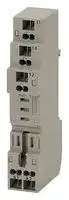


P2RF-05-S
Socket, MY/G2R Series Relays
- Manufacturer: OMRON INDUSTRIAL AUTOMATION
- Product type: Relay Sockets
- SVHC: To Be Advised
| Delivery and price | |
|---|---|
| Units per pack | 10 |
| Price | 57.25 € |
| Current stock | 10+ |
| Lead time | 30 days |
**Screwless Clamp Terminal Sockets PYF @@ S/P2RF- @@ -S**

CSM_PYF__S/P2RF-__-S_DS_E_2_5

## **New Screwless Terminal Sockets Added for MY and G2R Relays.**

- Simplified wiring without tightening screws.

- Two wires can be independently wired for each terminal.

- Coil terminals and contact terminals are completely separated in an organized wiring layout.

- Release Levers and Labels are available (sold separately).

## **Features**

## Structured for Easy Wiring

## Complete Wiring in Three Steps

**==> picture [393 x 148] intentionally omitted <==**

**----- Start of picture text -----**<br>
Contact terminal<br>(common)<br>Contact terminal  rrs<br>(NO)<br>Contact terminal<br>(NC)<br>Insert  Screwdriver  Insert the wire. Remove screwdriver<br>Release Lever  a screwdriver. inserted. to complete wiring.<br>(sold separately)<br>• A spring holds the wire in place to reduce wiring work by 30%<br>Coil terminals (according to OMRON comparison) and eliminates the need to<br>manage torque.<br>Label  • DIN terminal numbers also indicated.<br>(sold separately)<br>**----- End of picture text -----**<br>


## **Ordering Information**

## **Sockets**

|**Applicable model (typical example)**|**Socket**|
|---|---|
||**Model**|
|MY2|**PYF08S**|
|MY4|**PYF14S**|
|G2R-1-S|**P2RF-05-S**|
|G2R-2-S|**P2RF-08-S**|


## **Options (Order Separately)**

|**Applicable Socket**|**Release Bar**|**Labels**|**Short Bars with Red Insulation**|**Short Bars with Blue Insulation**|
|---|---|---|---|---|
||**Model**|**Model**|**Model**|**Model**|
|PYF08S|**PYCM-08S**|**R99-11**|**PYDM-08SR**|**PYDM-08SB**|
|PYF14S|**PYCM-14S**||**PYDM-14SR**|**PYDM-14SB**|
|P2RF-05-S|**P2CM-S**||**P2RM-SR**|**P2RM-SB**|
|P2RF-08-S|||||


**Note:** Pieces per Package Labels: 100 Short Bars: 50

**1** omRON ~~a~~

**PYF @@ S/P2RF- @@ -S**

## **Ratings/Characteristics**

## **Characteristics**

## **Sockets**

## **PYF** @@ **S**

|**Item**<br>**Model**|**Item**<br>**Model**|**PYF08S**|**PYF14S**|
|---|---|---|---|
|**Ambient operating temperature**||−55 to 70°C||
|**Ambient operating humidity**||5% to 85%||
|**Continuous carry current***||10 A|5 A|
|**Dielectric**<br>**strength**|**Between contact**<br>**terminals of same**<br>**polarity**|2,000 VAC, 1 min|2,000 VAC, 1 min|
||**Between contact**<br>**terminals of**<br>**different polarity**|2,000 VAC, 1 min|2,000 VAC, 1 min|
||**Between coil and**<br>**contact terminals**|2,000 VAC, 1 min|2,000 VAC, 1 min|
|**Insulation resistance**||1,000 MΩmin.||
|**Weight (approx.)**||46 g|62 g|


* The continuous carry current of 10 A for the PYF08S is for an ambient temperature of 55°C. At an ambient temperature of 70°C, the value is 7 A.

## **P2RF-** @@ **-S**

|**Item**<br>**Model**|**Item**<br>**Model**|**P2RF-05-S**|**P2RF-08-S**|
|---|---|---|---|
|**Ambient operating temperature**||−40 to 70°C||
|**Ambient operating humidity**||5% to 85%||
|**Continuous carry current**||10 A|5 A|
|**Dielectric**<br>**strength**|**Between contact**<br>**terminals of same**<br>**polarity**|1,000 VAC, 1 min|1,000 VAC, 1 min|
||**Between contact**<br>**terminals of**<br>**different polarity**|---|3,000 VAC, 1 min|
||**Between coil and**<br>**contact terminals**|4,000 VAC, 1 min|4,000 VAC, 1 min|
|**Insulation resistance**||1,000 MΩmin.||
|**Weight (approx.)**||36 g|40 g|


## **Socket Accessories**

## **Short Bars**

|**Application**|**Applicable sockets**|**Model**|**Maximum carry current**|**Ambient operating**<br>**temperature**|**Ambient operating**<br>**humidity**|
|---|---|---|---|---|---|
|For Coil terminals|PYF08S|PYDM-08S@|10 A|−40 to 70°C|5% to 85%|
||PYF14S|PYDM-14S@|10 A|−40 to 70°C|5% to 85%|


## **Ratings for Safety Standard Certification**

## **PYF** @@ **S**

|**Standard**|**File No.**|
|---|---|
|VDE0627 (EN61984)|Certificate No. 40015509|
|UL508 (UL1059)|E87929 Vol.3|
|CSA C22.2 No.14 (CSA C22.2 No.158)|LR31928|


## **P2RF-** @@ **-S**

|**Standard**|**File No.**|
|---|---|
|VDE0627 (EN61984)|Certificate No. 40002313|
|UL508 (UL1059)|E87929 Vol.3|
|CSA C22.2 No.14 (CSA C22.2 No.158)|LR31928|


**2**

**PYF@@S/P2RF-@@-S**

**Dimensions**

**(Unit: mm)**

## **Sockets**

## **PYF08S**

**==> picture [38 x 91] intentionally omitted <==**

**==> picture [287 x 196] intentionally omitted <==**

**----- Start of picture text -----**<br>
38.2 max.<br>36.5 max. Terminal Arrangement/<br>Internal Connection Diagram<br>(Top View)<br>12 9<br>(41) (11)<br>32.6<br>8 5<br>27.6<br>23.2 max. 22.6 (3.4) (44) (14)<br>4 1<br>24.5 (42) (12)<br>85 max. 35.4<br>(A2) (A1)<br>14 13<br>Note: Figures in parentheses indicate<br>(5) 28.6 (5.3) DIN standard numbers.<br>32.6<br>**----- End of picture text -----**<br>


## **PYF14S**

**==> picture [45 x 93] intentionally omitted <==**

**==> picture [296 x 193] intentionally omitted <==**

**----- Start of picture text -----**<br>
3 6.5 max.<br>Terminal Arrangement/<br>Internal Connection Diagram<br>(Top View)<br>12 11 10 9<br>(41) (31) (21) (11)<br>32.6<br>27.6 8 7 6 5<br>3 1 max. 22.6 (3.4) (44) (34) (24) (14)<br>4 3 2 1<br>24.55 (42) (32) (22) (12)<br>85 max. 35.4<br>(A2) (A1)<br>14 13<br>(4.15) 28.6 Note: Figures in parentheses indicate<br>32.6 DIN standard numbers.<br>**----- End of picture text -----**<br>


**3**

**PYF@@S/P2RF-@@-S**

## **P2RF-05-S**

**==> picture [304 x 186] intentionally omitted <==**

**----- Start of picture text -----**<br>
Terminal Arrangement/<br>Internal Connection Diagram<br>(Top View)<br>4<br>32.6 (11)<br>18.0 max. 27.6 3<br>22.6 (14)<br>2<br>24.5 (12)<br>35.3<br>91.8 max.<br>(A1) (A2)<br>5 1<br>(2.4) 28.5 (5.3)<br>32.6 Note: Figures in parentheses indicate<br>DIN standard numbers.<br>**----- End of picture text -----**<br>


## **P2RF-08-S**

**==> picture [287 x 191] intentionally omitted <==**

**----- Start of picture text -----**<br>
Terminal Arrangement/<br>Internal Connection Diagram<br>(Top View)<br>6 3<br>32.6 (21) (11)<br>18.0 max. 27.6 5 4<br>22.6 (3.4) (24) (14)<br>7 2<br>24.5 (22) (12)<br>35.3<br>91.8 max.<br>(A1) (A2)<br>8 1<br>(2.4) 28.6 (5.3)<br>32.6 Note: Figures in parentheses indicate<br>DIN standard numbers.<br>**----- End of picture text -----**<br>


**4**

**PYF @@ S/P2RF- @@ -S**

## **Accessories (Order Separately)**

## **Short Bars**

**==> picture [114 x 61] intentionally omitted <==**

**----- Start of picture text -----**<br>
Insulating coating<br>14<br>9<br>Length<br>Guide: 1.2 dia.<br>**----- End of picture text -----**<br>


|**plicable**<br>**ockets**|**Model**<br>**L**|**ength (mm)**|**Insulation**<br>**color**|
|---|---|---|---|
|S|**PYDM-08SR**<br>**PYDM-08SB**|19.7|Red|
||||Blue|
|S|**PYDM-14SR**<br>**PYDM-14SB**|27.5|Red|
||||Blue|
|@@-S|**P2RM-SR**<br>**P2RM-SB**|14.3|Red|
||||Blue|


**Note:** Use the Socket Bridges for relay coil bridge wiring.

## **Release Levers**

**==> picture [178 x 124] intentionally omitted <==**

**----- Start of picture text -----**<br>
PYCM-14S<br>28<br>52.5<br>29.6<br>**----- End of picture text -----**<br>


**==> picture [46 x 7] intentionally omitted <==**

**----- Start of picture text -----**<br>
PYCM-08S<br>**----- End of picture text -----**<br>


**==> picture [62 x 100] intentionally omitted <==**

**----- Start of picture text -----**<br>
16<br>54.4<br>32.7<br>**----- End of picture text -----**<br>


## **P2CM-S**

**==> picture [36 x 51] intentionally omitted <==**

**==> picture [60 x 65] intentionally omitted <==**

**----- Start of picture text -----**<br>
16.8<br>40.35<br>36<br>**----- End of picture text -----**<br>


## **Mounting Heights**

## **PYF08S**

**==> picture [34 x 8] intentionally omitted <==**

**----- Start of picture text -----**<br>
PYF14S<br>**----- End of picture text -----**<br>


## **P2RF-** @@ **-S**

**==> picture [511 x 116] intentionally omitted <==**

**----- Start of picture text -----**<br>
MY MY P2RF-@@-S  G2R Relay<br>Socket<br>73.6 64 72.6 64 64 *   (65) 57<br>(72) *<br>28.6 28.6<br>(3.4) (3.4)<br>Figures of height in () is with G2R Relays with Latching Lervers.<br>Values indicated with asterisks are for when using a PFP-N Track.<br>The values increase by approximately 9 mm when using a PFP-N Track.<br>**----- End of picture text -----**<br>


**5**

**PYF@@S/P2RF-@@-S**

## **Safety Precautions**

## **Precautions for Safe Use**

- Do not move the screwdriver up, down, or from side to side or rotate it while it is inserted in the hole. Doing so may damage internal components in the Socket.

## **Precautions for Correct Use**

## **Wiring Tools**

## **Applicable Screwdriver**

Use a flat-blade screwdriver with a tip that is 2.5 mm wide (3.0 mm max.).

2.5 mm (3.0 mm max. )

- Do not insert more than one wire into the same hole. Doing so may cause abnormal heating.

- There are two internally connected wiring holes for each terminal.

- Insert the screwdriver along the hole wall as shown below.

You cannot use a screwdriver with a thick shaft.

Applicable Screwdriver (Example) VESSEL No.9900 − (−) 2.5 × 75

## **Applicable Wires**

- You can use either solid wires or stranded wires. Applicable wire size: 0.2 to 1.5 mm[2] (AWG24 to AWG16)

- Strip 8 to 9 mm of insulation from the ends of the wires.

## Screwdriver

- When you remove a Socket from a support rail, insert the end of a screwdriver into the fixture and move the screwdriver as shown by the arrow in the following figure.

## 8 to 9 mm

- If you insert stranded wires without ferrules, make sure that the wires are twisted when you insert them.

- If you use bare ferrules, always attach insulating sleeves.

**==> picture [38 x 7] intentionally omitted <==**

**----- Start of picture text -----**<br>
Screwdriver<br>**----- End of picture text -----**<br>


- If you insert a wire with a sheath outer diameter of 2.2 mm or less, do not insert the wire far enough so that the sheath is engaged inside the hole, as shown below.

**==> picture [34 x 6] intentionally omitted <==**

**----- Start of picture text -----**<br>
Fixture rail<br>**----- End of picture text -----**<br>


- When you use a Release Lever to remove a Relay from a P2RF@@-S Socket, insert a screwdriver at the location shown in the following figure and move the Release Lever in the direction indicated by the arrow to release the lock on the release lever.

- Two wires with a sheath outer diameter of 3.2 mm or larger cannot be inserted for the same terminal at the same time.

- Use heat-shrinking tubes to indicate wire numbers.

**6**

**PYF@@S/P2RF-@@-S**

## **Wiring**

**==> picture [228 x 79] intentionally omitted <==**

**----- Start of picture text -----**<br>
> A<br>12 11 10 9<br>Wire insertion holes<br>41 31 21 11<br>Screwdriver insertion holes<br>neljea|neea<br>—> A<br>**----- End of picture text -----**<br>


- (1) Insert a screwdriver into a screwdriver insertion hole on the Socket.

**==> picture [173 x 77] intentionally omitted <==**

**----- Start of picture text -----**<br>
Cross-section A-A Spring<br>el Wire insertion hole<br>Screwdriver<br>=e<br>Screwdriver insertion hole<br>**----- End of picture text -----**<br>


- (2) Press the screwdriver in until it reaches the stopper inside the Socket. The spring at the back of the wire insertion hole will be completely open in this condition. The screwdriver will be held in place even if you remove your hand.

- (3) With the screwdriver held in place, insert the wire or ferrule into the wire insertion hole.

_— ee Wire

- (4) Remove the screwdriver. The spring will hold the wire. This concludes the connection procedure.

**7**

## Terms and Conditions Agreement

## Read and understand this catalog.

Please read and understand this catalog before purchasing the products.  Please consult your OMRON representative if you have any questions or comments.

## Warranties.

(a) Exclusive Warranty. Omron’s exclusive warranty is that the Products will be free from defects in materials and workmanship for a period of twelve months from the date of sale by Omron (or such other period expressed in writing by Omron). Omron disclaims all other warranties, express or implied.

(b) Limitations. OMRON MAKES NO WARRANTY OR REPRESENTATION, EXPRESS OR IMPLIED, ABOUT NON-INFRINGEMENT, MERCHANTABILITY OR FITNESS FOR A PARTICULAR PURPOSE OF THE PRODUCTS. BUYER ACKNOWLEDGES THAT IT ALONE HAS DETERMINED THAT THE

PRODUCTS WILL SUITABLY MEET THE REQUIREMENTS OF THEIR INTENDED USE.

Omron further disclaims all warranties and responsibility of any type for claims or expenses based on infringement by the Products or otherwise of any intellectual property right. (c) Buyer Remedy. Omron’s sole obligation hereunder shall be, at Omron’s election, to (i) replace (in the form originally shipped with Buyer responsible for labor charges for removal or replacement thereof) the non-complying Product, (ii) repair the non-complying Product, or (iii) repay or credit Buyer an amount equal to the purchase price of the non-complying Product; provided that in no event shall Omron be responsible for warranty, repair, indemnity or any other claims or expenses regarding the Products unless Omron’s analysis confirms that the Products were properly handled, stored, installed and maintained and not subject to contamination, abuse, misuse or inappropriate modification. Return of any Products by Buyer must be approved in writing by Omron before shipment. Omron Companies shall not be liable for the suitability or unsuitability or the results from the use of Products in combination with any electrical or electronic components, circuits, system assemblies or any other materials or substances or environments. Any advice, recommendations or information given orally or in writing, are not to be construed as an amendment or addition to the above warranty.

See http://www.omron.com/global/ or contact your Omron representative for published information.

## Limitation on Liability; Etc.

OMRON COMPANIES SHALL NOT BE LIABLE FOR SPECIAL, INDIRECT, INCIDENTAL, OR CONSEQUENTIAL DAMAGES, LOSS OF PROFITS OR PRODUCTION OR COMMERCIAL LOSS IN ANY WAY CONNECTED WITH THE PRODUCTS, WHETHER SUCH CLAIM IS BASED IN CONTRACT, WARRANTY, NEGLIGENCE OR STRICT LIABILITY. Further, in no event shall liability of Omron Companies exceed the individual price of the Product on which liability is asserted.

## Suitability of Use.

Omron Companies shall not be responsible for conformity with any standards, codes or regulations which apply to the combination of the Product in the Buyer’s application or use of the Product. At Buyer’s request, Omron will provide applicable third party certification documents identifying ratings and limitations of use which apply to the Product. This information by itself is not sufficient for a complete determination of the suitability of the Product in combination with the end product, machine, system, or other application or use. Buyer shall be solely responsible for determining appropriateness of the particular Product with respect to Buyer’s application, product or system. Buyer shall take application responsibility in all cases.

NEVER USE THE PRODUCT FOR AN APPLICATION INVOLVING SERIOUS RISK TO LIFE OR PROPERTY OR IN LARGE QUANTITIES WITHOUT ENSURING THAT THE SYSTEM AS A WHOLE HAS BEEN DESIGNED TO ADDRESS THE RISKS, AND THAT THE OMRON PRODUCT(S) IS PROPERLY RATED AND INSTALLED FOR THE INTENDED USE WITHIN THE OVERALL EQUIPMENT OR SYSTEM.

## Programmable Products.

Omron Companies shall not be responsible for the user’s programming of a programmable Product, or any consequence thereof.

## Performance Data.

Data presented in Omron Company websites, catalogs and other materials is provided as a guide for the user in determining suitability and does not constitute a warranty. It may represent the result of Omron’s test conditions, and the user must correlate it to actual application requirements. Actual performance is subject to the Omron’s Warranty and Limitations of Liability.

## Change in Specifications.

Product specifications and accessories may be changed at any time based on improvements and other reasons. It is our practice to change part numbers when published ratings or features are changed, or when significant construction changes are made. However, some specifications of the Product may be changed without any notice. When in doubt, special part numbers may be assigned to fix or establish key specifications for your application. Please consult with your Omron’s representative at any time to confirm actual specifications of purchased Product.

## Errors and Omissions.

Information presented by Omron Companies has been checked and is believed to be accurate; however, no responsibility is assumed for clerical, typographical or proofreading errors or omissions.

**In the interest of product improvement, specifications are subject to change without notice.**

## **OMRON Corporation**

## **Industrial Automation Company**

2018.5

**http://www.ia.omron.com/**

(c)Copyright OMRON Corporation 2018 All Right Reserved.
Updated at June 6, 2026
With a legacy spanning over 80 years, Omron Industrial Automation is a globally recognized leader in the manufacture of advanced industrial control and automation components. Renowned for their reliability and engineering excellence, Omron delivers comprehensive solutions that enhance efficiency, machine safety, and precision across a wide range of manufacturing environments. Our extensive portfolio of Omron products is heavily focused on their industry-leading sensing and switching technologies. We offer a vast selection of sensors, excelling specifically in high-performance proximity sensors, light sensors, and temperature sensors. Complementing this range are robust switching solutions, featuring a deep inventory of power relays, solid-state relays, safety relays, and essential relay accessories designed for demanding operational requirements. Beyond sensing and switching, Omron is highly regarded for its precision automation and process control equipment. Our selection features highly accurate temperature controllers, versatile process controllers, and sophisticated panel displays and instrumentation. To support these fundamental systems, we also supply dependable Omron power supplies, notably AC/DC converters, alongside vital connectivity components like DIN rail terminal blocks to ensure secure, efficient, and complete industrial setups.
About Novapart
Novapart is a B2B electronic component broker specialising in stock shortages and cost reduction. We source hard-to-find parts and identify compliant alternatives across a catalogue of 410,000+ components from 500+ manufacturers.
Learn more →Stock Shortage Specialist
When a component is unavailable, discontinued or has an unacceptable lead time, we tap into our network of vetted European and Asian distributors to source what you need — without compromising on quality or traceability.
Request a quote →Compliant Alternatives
We identify pin-to-pin, electrically equivalent substitutes that meet the same certifications (RoHS, AEC-Q100, REACH) as your original specification — validated against datasheets, not just part numbers. Often at a lower cost.
BOM Analysis service →